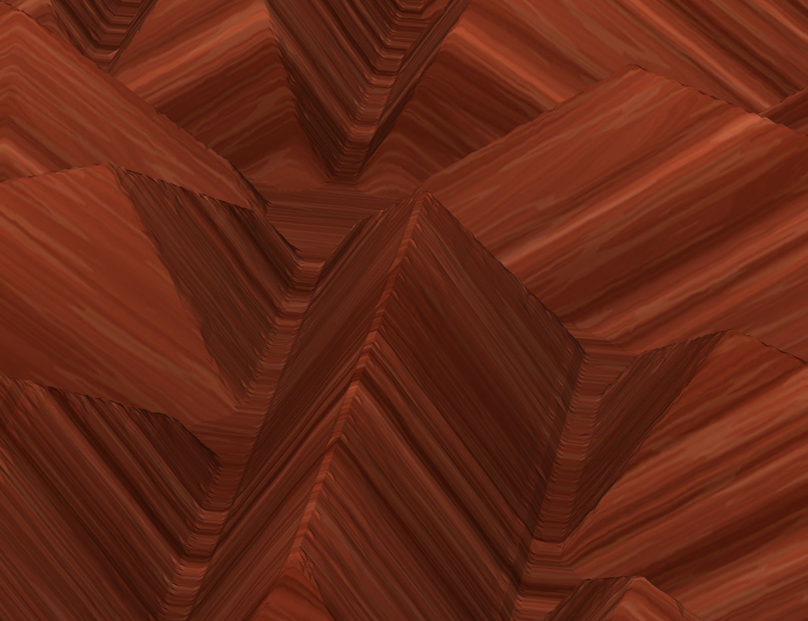
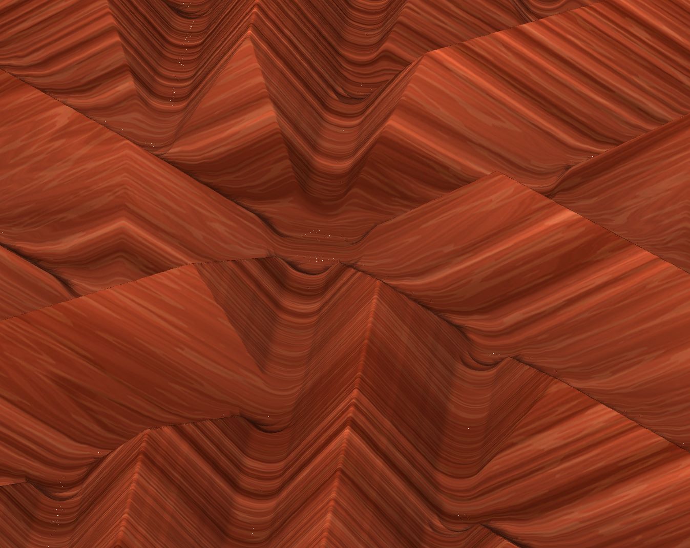
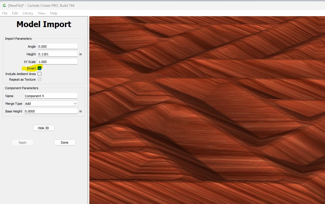
When I go to create the 3D finishing toolpath with the standard 1/8 square mill, I’m seeing strange artifacts / dips in the center and where the shapes meet. This indeed shows up on the final output too. I’ve tried all the import combinations/debugging/hacks I could think of, but fundamentally can’t get it to produce what I think should be the correct output.
It looks like you are using a ball mill, and too large to get all the way down in those valleys. What size is your workpiece? I imported it at 8x8" and it needs a 1/32" end mill to get to the bottom of the valleys.
Inverting is a straightforward concept to understand but it has no relevance to the issue.
The problem with the valleys is that they shouldn’t exist at all. The original post was about comparing the 3D model import with the toolpath simulation. It seemed strange & wrong to me that it would attempt to dig those areas at all.
I ended up writing my own heightmap mesher based on the paper “Fast Polygonal Approximation of Terrains and Height Fields” and used it to refine the input heightmap so I could get Carbide Create to recognize the flat areas during toolpath generation, even though the 3D preview on import was virtually identical.