Hi -
I am trying to adjust the movement of my step motor I have set up to do rotary work.
The rotary files are created with Aspire. I slave the Y axis’s to this step motor…
K12-100 (Nema 23) 1.8 degree / 200 (reducing ratio 6:1)
10 teeth 5mm pitch
I don’t know what the micro steps are but I assumed 16
So after using an online steps/mm calculator I adjusted $101 = 40 to $101=32 , $101=64
I also tried several other values by interpolating but no success.
Is anyone familiar with this? Does anyone have any thoughts on how to adjust the motor? Could it be the post processor is not adequate?
I also tried to run it on CNCJs and still same results.
Thank you so much for your help!!
Gabe
Topic should have read …steps per mm
My rotary is working with properly calibrated steps, with a Nema-23, 1.8deg/200, and I believe a 6:1 ratio drive gear/belt the same as yours.
If I recall, and @Julien might be able to correct, that Carbide’s Controller is using 8 micro-steps (compromise between resolution and holding torque).
I will download my current $$ settings from my controller and post them here, hopefully later today (a Teensy4.1/Grbl-HAL replacement on my ShapeOKO 3XL so I don’t have to slave the Y axis wiring for the Rotary - mine is as a consequence of this a true XYYZA setup, with homing sensors on XYZ and A).
Excerpt from my Grbl-HAL firmware as compiled;
// STEPS_PER_MM is (Steps for 1 rotation * microsteps) / mm achieved per rotation
// Typical GT2 belt is 2mm per tooth, a 20-tooth ‘gear’ on stepper thus 40mm/rotation
// Thus (200 * 8) / 40 = 40 for 1.8deg stepper, 8 microsteps, 20-tooth on GT2
#define DEFAULT_X_STEPS_PER_MM 40.0f //250.0f
#define DEFAULT_Y_STEPS_PER_MM 40.0f //250.0f
#define DEFAULT_Z_STEPS_PER_MM 320.0f //250.0f
My actual, just downloaded $$ settings. Note that as my machine has a permanent A-Rotary axis, I have $103 defined, and similarly $113, $123 and $133. I also have the HDZ upgrade, so my Z settings may look different to yours.
$100=40.000 (X-axis travel resolution, step/mm)
$101=40.000 (Y-axis travel resolution, step/mm)
$102=320.000 (Z-axis travel resolution, step/mm)
$103=26.667
$110=4000.000 (X-axis maximum rate, mm/min)
$111=4000.000 (Y-axis maximum rate, mm/min)
$112=660.000 (Z-axis maximum rate, mm/min)
$113=6480.000
$120=350.000 (X-axis acceleration, mm/sec^2)
$121=350.000 (Y-axis acceleration, mm/sec^2)
$122=80.000 (Z-axis acceleration, mm/sec^2)
$123=300.000
$130=878.000 (X-axis maximum travel, mm)
$131=430.000 (Y-axis maximum travel, mm)
$132=140.000 (Z-axis maximum travel, mm)
$133=1440.000
This is a trial and error procedure…When I installed my 4th axis, setting the steps is a normal calibration procedure. My rough in method was to clamp a parallel to the 4th, place a dial indicator at its further’s point (and still be able to clear a 360º rotation.) Adjust the steps until I could rotate the rotary and have the dial show zero (0) error with a 180º rotation. Then fine check it at 360, 720, 1440, ever so slowly adjusting the steps per millimeter to a 4 place decimal. (and WRITE this number down for future reference)
Also check in reverse to check the rotary’s backlash (so you know this information, and record it.)
PS No need to post my number of steps per mm, since it will vary greatly from rotary to rotary.
1 Like
Thank you! I will mess around with this. great information
thanks
Also good info! Thanks and good tip on the reverse direction check
Quick question. Once I get a starting value for the “A” axis rotation (in my case $101=?) Can I fine tune this the same way I would with linear motion? Ie. To fine tune my x axis I would command a distance. Then measure the actual distance traveled. Then make adjustment
I use this taken from diymachining.com
Updated Steps/mm = (Current Steps/mm) x (Commanded Travel) / Dial Indicator Reading
Current Steps/mm – The current GRBL settings
Dial Indicator Reading – The actual distance traveled by the machine
Commanded Travel – The distance the machine was told to move form the computer interface
Updated Steps/mm – The new value you enter into GRBL
This can be further simplified if you always command the system to move 1”.
Then the formula becomes…
Updated Steps/mm = (Current Steps/mm) / (Dial Indicator Reading)
I see no reason why not. It is just another axis ‘moving’ through a chain of steps, rotation and linear movement. The only difference is for the Rotary Axis, ‘linear movement’ is now in degrees.
You may have to think about how you ‘command a movement of 1’ to be the same as 1deg of rotation, but it should nut out quite easily.
If I recall, I commanded 360deg rotation and measured the angular error after the rotary had stopped moving, and then pro-rated a tiny bit on the steps/per setting in $$. If 361deg happened on commanding 360deg, I changed my $103=26.6667 by 360/361 = 26.5928 to effectively ‘slow down’ the physical movement to match.
As you can’t have 0.667 of a step, you need to move many tens or hundreds of steps so you don’t get a ‘rounding error’. Asking the machine to move 1deg will give 26 or 27 steps, probably rounds up so 27, and the difference between 27 and the intended 26.667 is a massive rounding error
Except accurately measuring the “actual angle” is a challenge. (Unless you have the right tools)
Probably easier to measure how many steps it takes to get to 360°, then do the math from there.
Then test 720, 1080, 1440 to increase the accuracy.
1 Like
I will try that. Got some work to do this week end. Thanks All!!
Andy –
I am thinking about rebuilding my control box like you did with the teensy 4.1 / Grbl HAL
Would you still recommend the teensy controller or is there something else more recent? I was reading some online stuff and I came across reference to TinyG (G Core) and an Andruino DUE. Is GRBL HAL and Gcore different?
I’m not very well versed in this stuff, but basically want to have a rotary axis I don’t have to slave as well and still use my VF spindle, bit setter and z probe etc.
Any thoughts?
Thanks!
Gabe
4th axis very cool. Having full XYZA control even cooler. You guys mind posting some pics of your setups? Wondering if you embed the rotary it into the table bed somehow (like how Dennis van hood does w his manual rotary setup)? Otherwise it seems like workpiece diameter would be very limited due to the short Z travel? Anyway this is very cool to see people getting this working.
J here is my 4th axis setup on the shapeoko 3. I just removed the 3 mdf boards that serve as the base.
Now if I can just fine tune the A axis step motor. Ha!
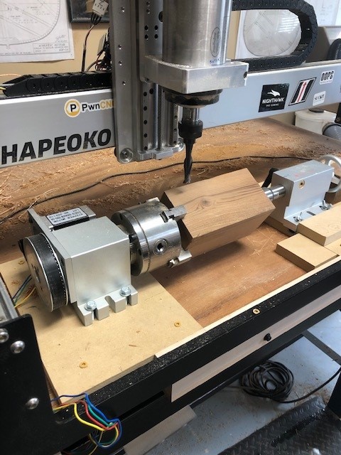
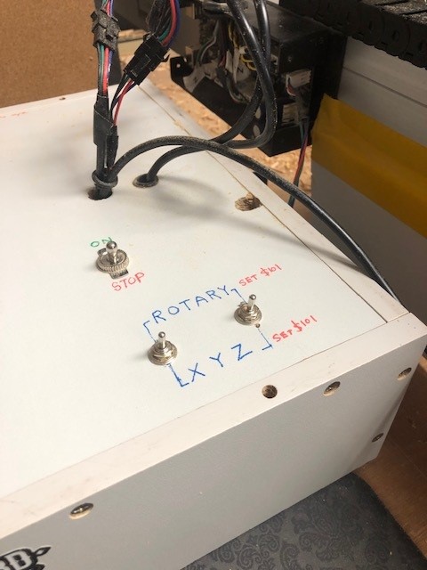
As mentioned in previous post I want to change motion controller so I don’t have to use the double switches when I am doing rotary work.
1 Like
@Gab The Teensy 4.1 is based on the ST MicroElectronics ST32 series of chips, which are reasonably new and certainly performant compared to the CNC control task - two orders of magnitude more powerful than the original Atmel 328p used on the Uno.
Others may chime in, but I saw and still see no reason to reach for higher performance than the Teensy - it simply isn’t needed.
You will need a break-out board (I used Phil Barret’s board) and also to get and wire up external Stepper Driver bricks (I used the DM3230 digital driver). You can re-use the existing power brick, but will have to change the connector at the DC end - or get a replacement brick.
The PB Break-out board has all of the outputs (such as PWM) and inputs (limit switches etc) that your existing machine has, plus it has a load more that may or may not be of interest or use.
With the Teensy/PB Break-out plugged together, you also have to get, configure and upload the GRBL-HAL firmware. If you are familiar with Arduino.cc programming, tinkering with Arduino Uno’s etc, then this will be familiar… otherwise there is a steep learning curve here.
I am very pleased with my upgrade. Found no difficulties with the programming, wiring, setup etc, but I tinker with microcontrollers and so am very familiar with the whole subject.
The number of people who will be able to help you out if you get stuck will be small, and those who are physically near to you (eg: send the Teensy to program it) even fewer - for example, I am in Europe and not really able to help much more than a bit of advice here or there in this forum.
There are other alternatives to GRBL-HAL. GRBL derivative Mega 5X is a simple hack of Grbl 1.1f and can run on 16 bit (if I remember) Arduino boards - but you still have most of the above issues to address and manage. If what you choose is not GRBL, you will have to ensure your CAD/CAM and Post-Processor can create .nc files for that language, and your Sender can cope with them too - unless you really know what you are doing or choosing in this regard, I would avoid it.
1 Like
Thanks! I will start my research
G
You are going to end up with something like the below;
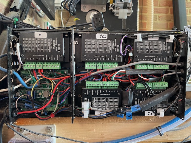
I wanted the controller box to fit on the SO3XL Y rail, in order to not have to extend any of the wiring, and as a result got a bit obsessed with making the whole thing as small as possible. It works, but it is a bit cramped and the wiring is not as neat as I really like - but it works.
1 Like
This topic was automatically closed after 30 days. New replies are no longer allowed.