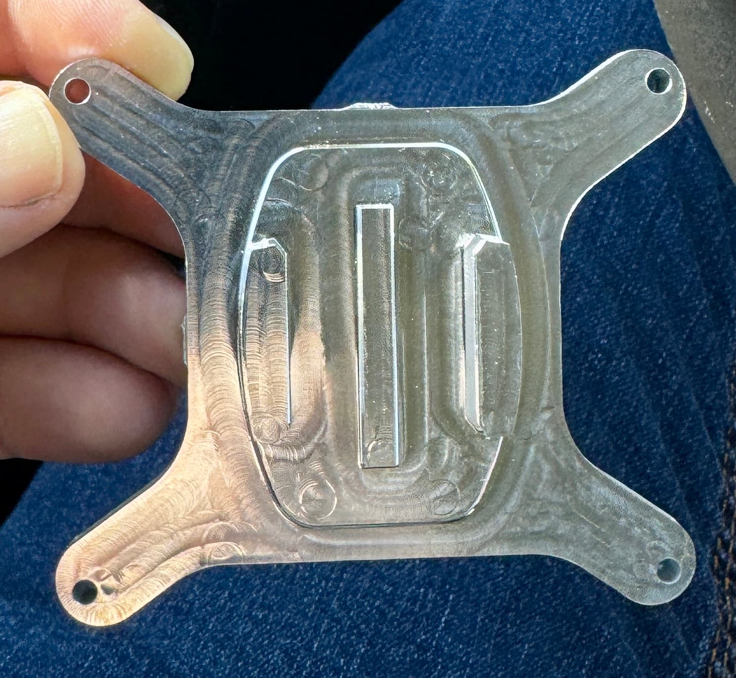
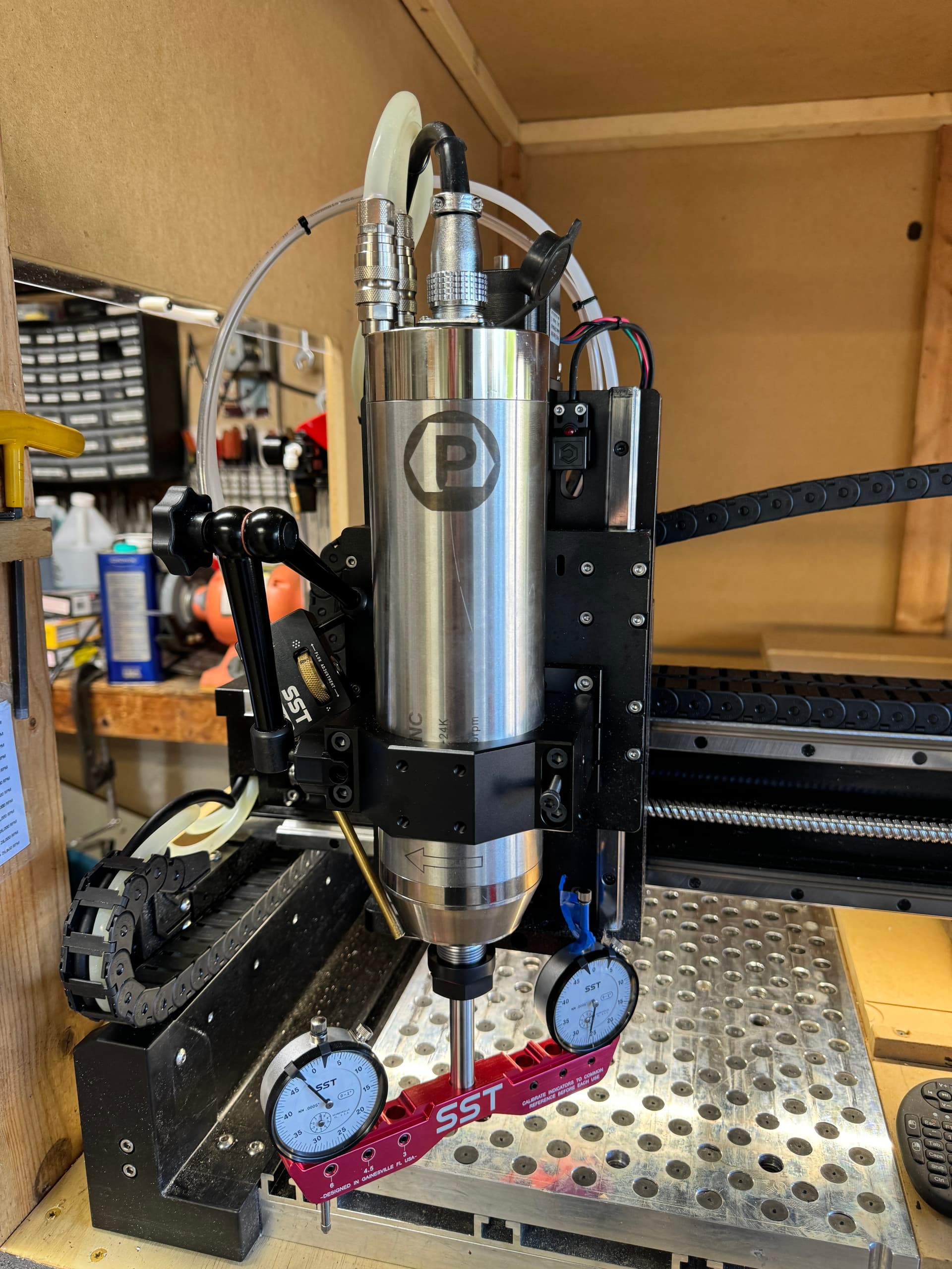
I would like to ask a few questions if you do not mind, It is because I have just obtained that spindle (80mm x 2.2kw from PwnCNC?) to go with my recently upgraded Z axis by way of the sturdier HDZ unit. Looking at the swirl marks, can you say what the deflection in the gantry/spindle was when you measured it? Do you think the marks are caused by a continuous fine oscillation in the spindle mounting, the X rail or both?
The spindle looks high in the mount but it clearly gives you a good Z height. I may very well be mistaken but can the spindle mount be located further up the Z axis plate? If so, would that have an effect on the tendency for the spindle to move in the mount? I suppose a proof of that concept would be to lower the spinle in the spindle mount and see what effect that has on your measured deflectiuons. In your opinion is the spindle movement front to back, side to side or both? Does the tooling type used have any affect on the floor finish markings?
My rails are from the Standard sized SO3 with its 16 x 16" work envelope. I deliberately chose the smallest machine because I wanted to address/suppress the potential issue of rail flexibility with larger machines. Although 5mm thick rectangular box section rails look very strong, I had an issue initially with some flexing. In the event I had not taken sufficient care to tighten everything correctly during assembly.
I changed the baseboard for an SMW fixture tooling plate and took great care in locating the endplate rail bolts correctly. With the threaded sections open by about 1/4 of the hole diameter on one side, I found it possible to misplace the starting threads of the bolts. One the bolt was aligned and squared properly, I subjected the bolts to as much torque as I could to hold the bolts and not break the heads or spall the threads.
Once I could see that there was no movement in the X rail, I was able to work well enough. I used an endmill with a straight edged two flute cutter, or a single flute cutter, to mill aluminium and not leave any discernible machining marks on the surface. (image to follow)
Depending on the measured amount of your X rail deflection, i would probably wish to consider using formal cap heads rather than the supplied button headed allen bolts (possibly even use high tensile). Maybe recutting the bolt threads which, AFAICT, had enough meat on the extrusion to permit a larger bolt cross section through the extrusions and the endplates, I also toyed with the idea of adding 1/8" index pins to the ends of the extrusions and locating them in the endplates as square as possible.
Possibly adding an extended length spindle mount and or drilling more holes into the Z axis so the spindle mount could be mounted higher om the Z axis without losing any Z height available to the spindle. It could help control any oscillations in the spindle casing. Just a few thoughts FWiW. Please feel free to reject any or all of these thoughts.