A box in 2 (or 3, or 4, maybe 5) Toolpaths and a few operations

Possibly a bit simpler than the Blind Miter w/ Hidden Boxjoint box:

https://willadams.gitbook.io/design-into-3d/blind-miter-box-joints

would be a Quarter Blind Boxjoint:

https://www.blockscad3d.com/community/projects/1432012

As always, we start w/ the dimensions:

  • 204 mm wide
  • 70 mm deep
  • 42 mm high
  • 8 mm thick stock

Lid options are the usual:

  • sawn
  • sliding
  • hinged

Sliding is probably the simplest, but hinged has an interesting limitation if one wants the hinge hidden, so we’ll do that.

First, draw up the joint as seen from overhead:

including a visualization of where the hinge will appear, since it will need to be considered.

We draw in the joints/fingers/pockets:

which makes it obvious we need to shorten the part along the edge where the end grain will show by stock thickness - length of joint:

Arrange an overview of the parts:

Then draw in the geometry to cut out the front/back for the lid:

and Boolean subtract:

The bottom will be in a rabbet half the thickness of the board which is inset by half the thickness of the board:

and if need be, mirror them vertically to get the needed arrangement:

The space in-between those elements will be taken up by the joinery:

Divide its height by the number of joinery part pairs:

Drag it into position and add suitable dogbones:

Then use the Linear Array command to create the duplicates for the joinery:

Offset the part geometry by endmill diameter plus 10%:

Then select and copy-paste in-place the joinery geometry and select the outline and joinery geometry for one part:

and mirror it horizontally:

Repeat for the other part:

Delete any excess geometry:

The upper and lower geometry on the ends needs to be larger so as to make a pocket for the uncut areas at the top and bottom:

which of course needs to be duplicated and mirrored over to the other side:

Each is then Boolean subtracted from the underlying geometry (or one can use the Trim Vectors tool to separate things and Join Vectors to stitch back together):

It will also be necessary to cut across the bottom for the bottom rabbet:

and reduce the geometry which defines the ends to account for the endgrain which will be left uncut on the front/back:

1 Like

Duplicate the geometry which defines the front/back and the offset geometry and put it and the geometry which defines the end dimensions on a suitable layer:

Select the geometry which defines the front/back and the joinery:

and use the Trim Vectors tool to reduce it to only what is needed, then join it together:

moving it together w/ duplicates of the offset geometry to a suitable layer:

Assigning toolpaths is then just a matter of associating them w/ the layers in question:

and

which just wants a geometry for the dogbones if they are too small to be cut w/ the selected tool.

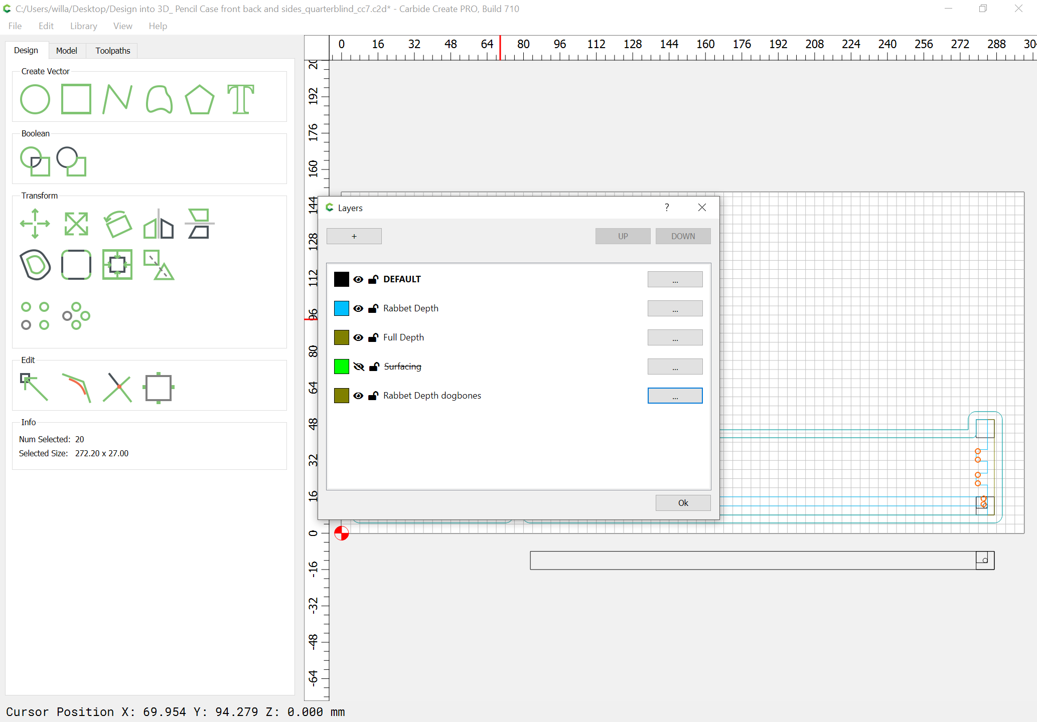
The most expedient way to handle the dogbones is to simply draw in the geometry for them:

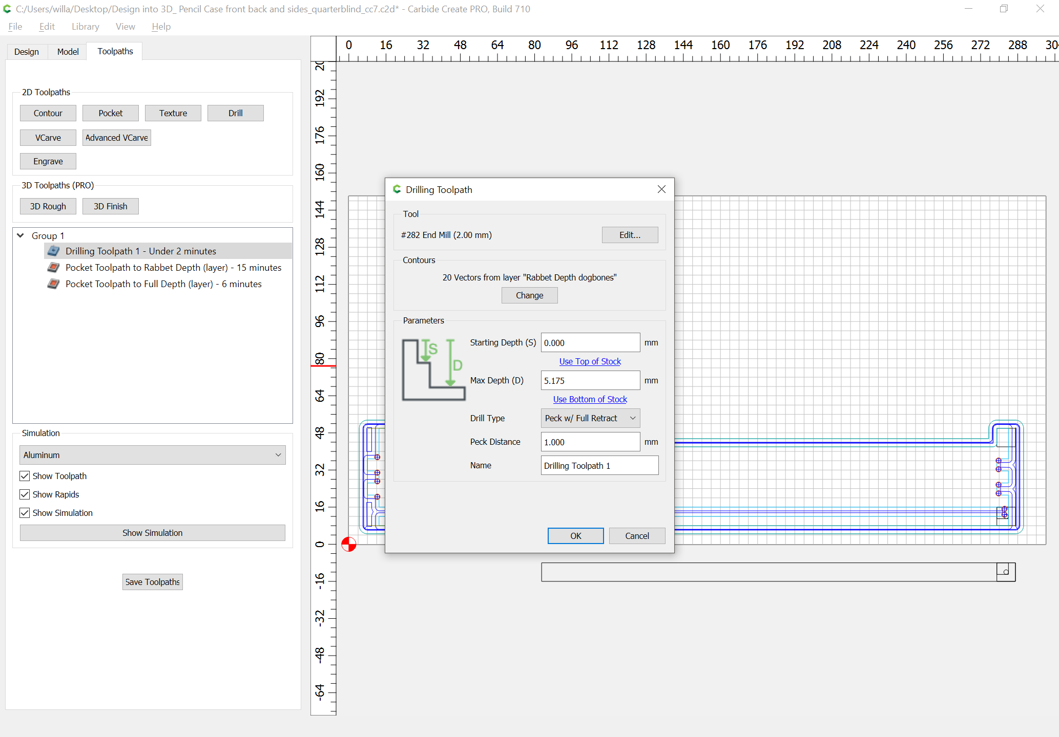
which, w/ a drill toolpath:
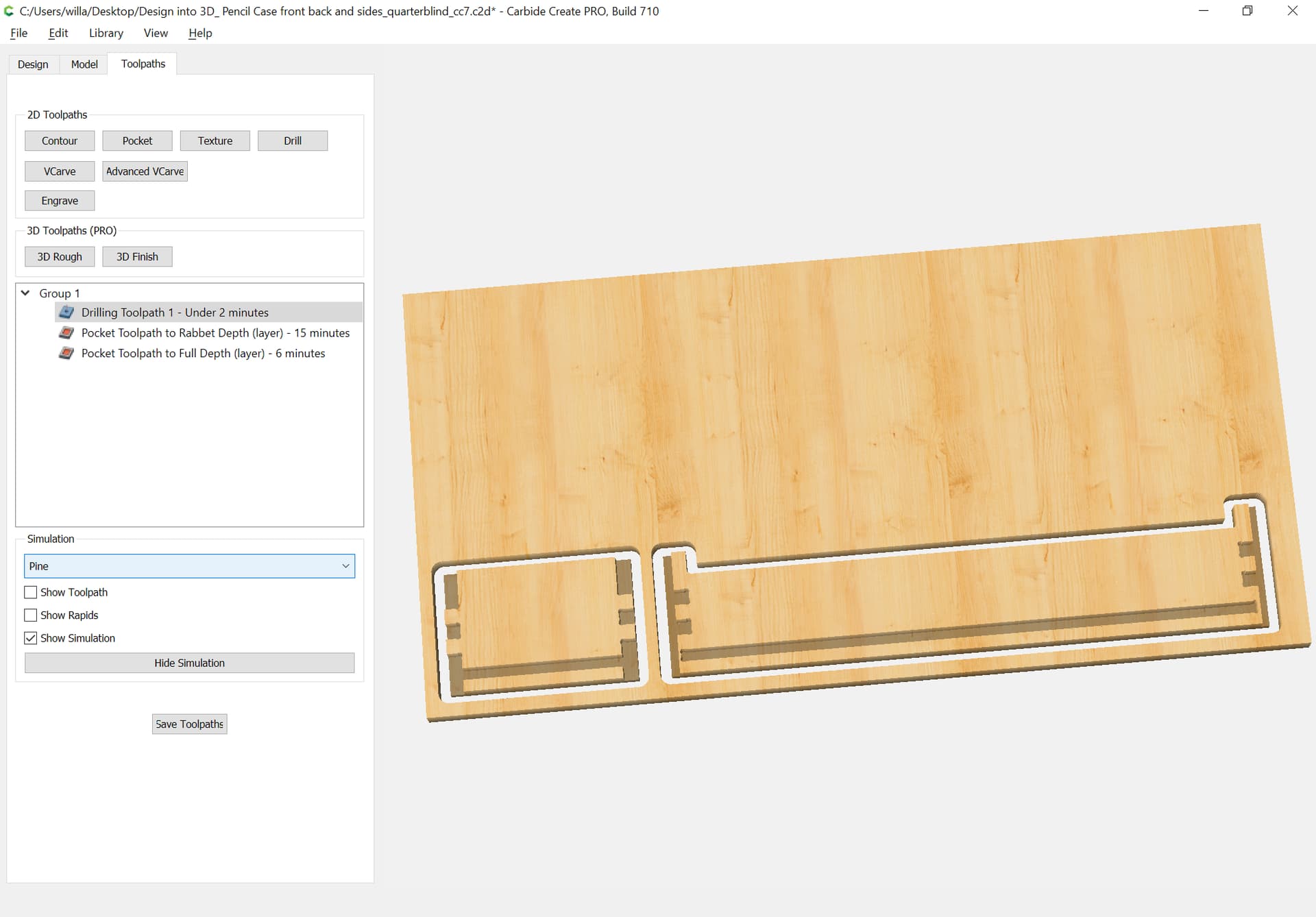
previews as:

Lastly, one just has to duplicate and arrange things for an optimal use of stock.

1 Like