Carbide 3D Community Site
A different sort of box
Unsupported
WillAdams
(William Adams (Carbide 3D))
February 14, 2022, 1:55am
10
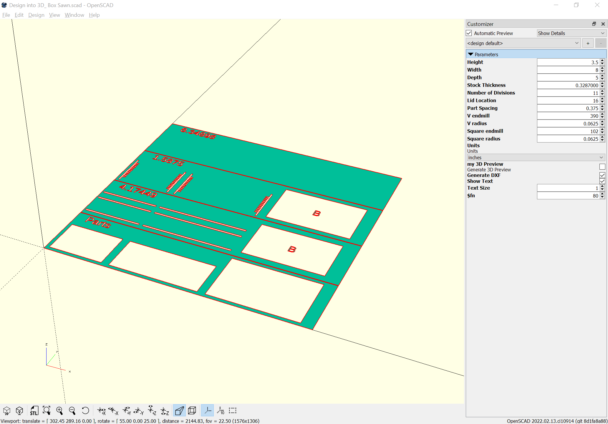
Success:
image
2065×1440 100 KB
(improved on by adding some notes on depth and so forth)
1 Like
show post in topic