A different sort of box

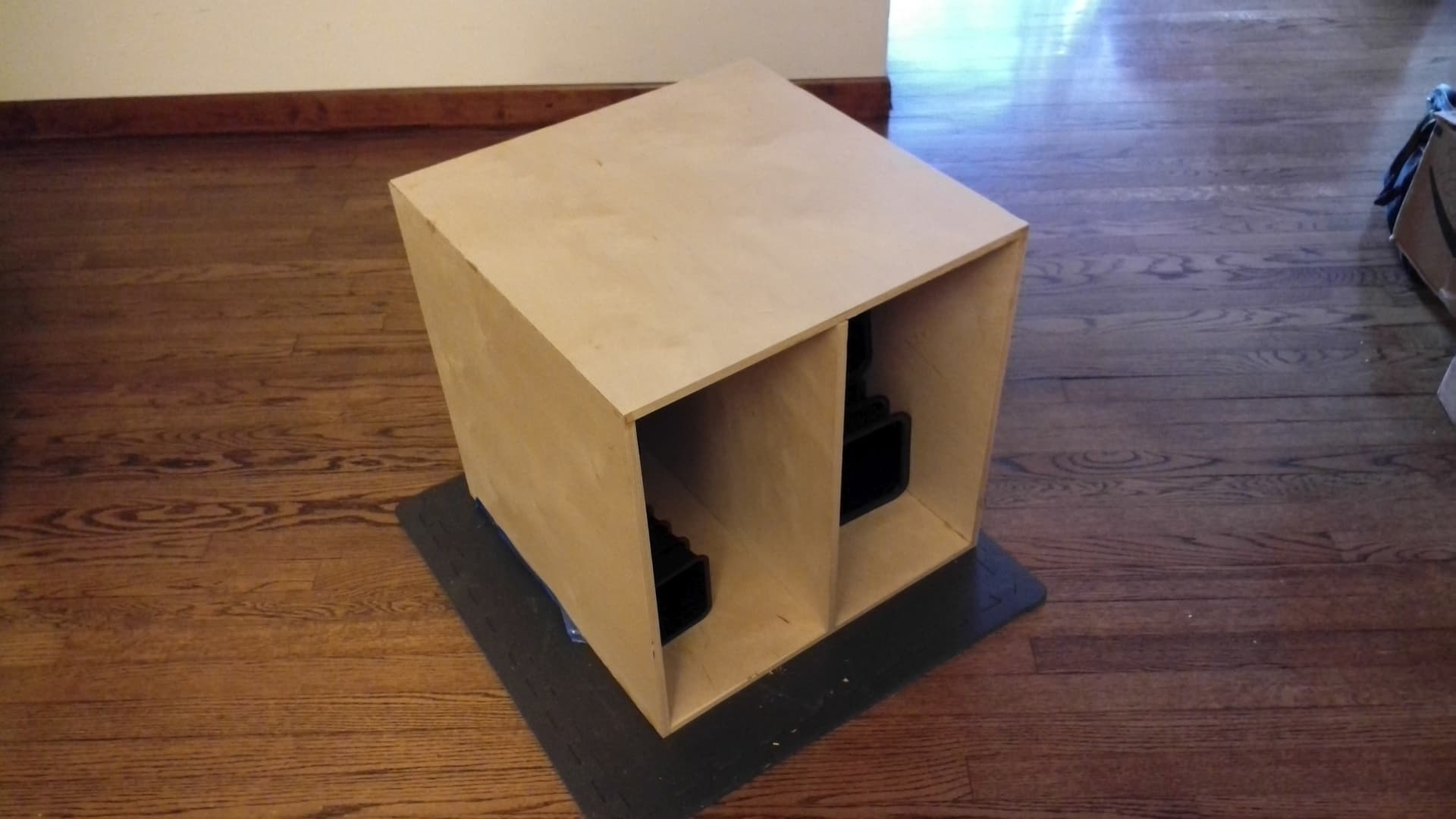
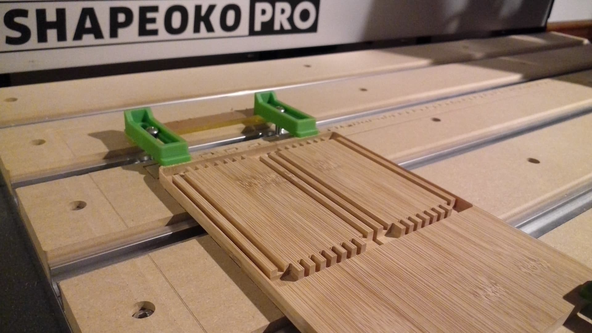
Building from a couple of different ideas[1][2], and giving up on the perfection of void-free, and limiting tools to a reasonable number (2), I have arrived at:

https://www.blockscad3d.com/community/projects/1270618

which allows one to cut out a box in 2, 3 or 4 operations:

  • bottom (cut to size)
  • top (cut to size) — possibly combined w/ the bottom
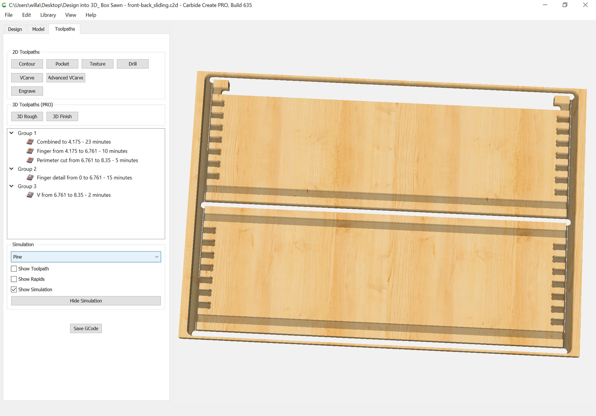
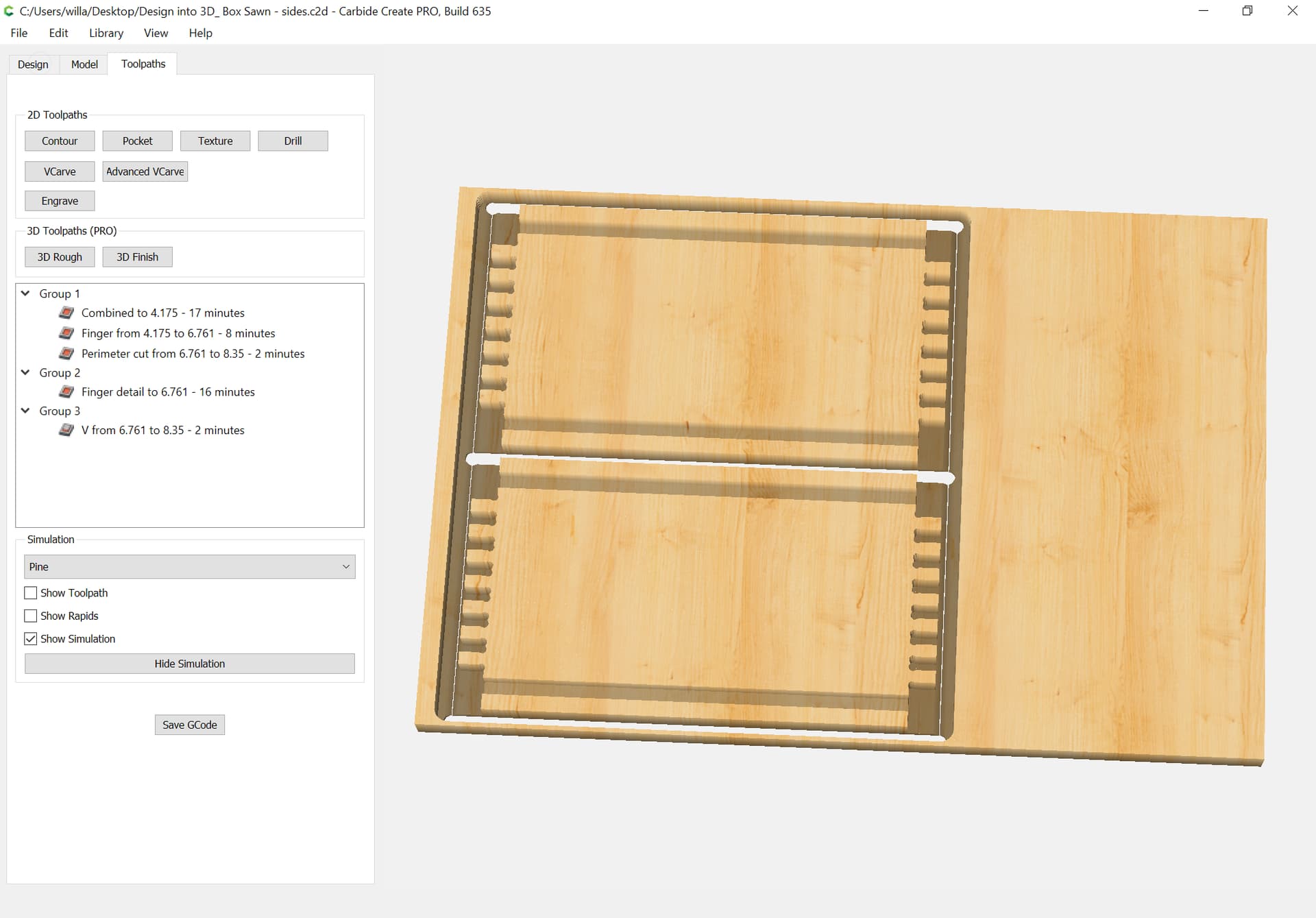
  • front/back and one or both sides (repeat once for 2 operations if need be) — this will cut the joinery blind box joints and miter as well as feature for lid, bottom, and a relief cut to ease sawing the lid off

using only two tools:

  • a small endmill
  • a narrow V endmill

Questions include:

  • is there a source for 3/16" diameter 90 degree V endmills suitable for wood? Other sizes? (possibly, see below)
  • would the improved aesthetics of the miter only showing justify the added complexity of multiple V endmill passes at the top/bottom? Note that it’s pretty simple to add this afterwards
  • are the dogbones small enough that the slight bit of them which will show along the inside of the box be okay? Would folks choose to line the boxes? The alternative would be a Tee which would not show, but would increase the volume of the voids

[1]

[2]

(for more on that design see: https://willadams.gitbook.io/design-into-3d/adjustable-modular-designs )

1 Like

In case anyone wishes to experiment with this:

Here’s a .c2d file which shows the concept:

all joints_0_25_x_3_5_sawnlid.c2d (139.5 KB)

1 Like

A quick search on endmills reveals:

a 1/4" Amana endmill:

2-flute tools in a variety of diameters:

drill-mills in a couple of diameters:

and a source for 1/8" drill-mills at what seems a very reasonable price:

Final steps are preparing a file for cutting.

New version at:

https://www.blockscad3d.com/community/projects/1273988

Which adds a “Generate DXF” option which renders as:

(and needs to have the V miter area added to the joint area, hang on)

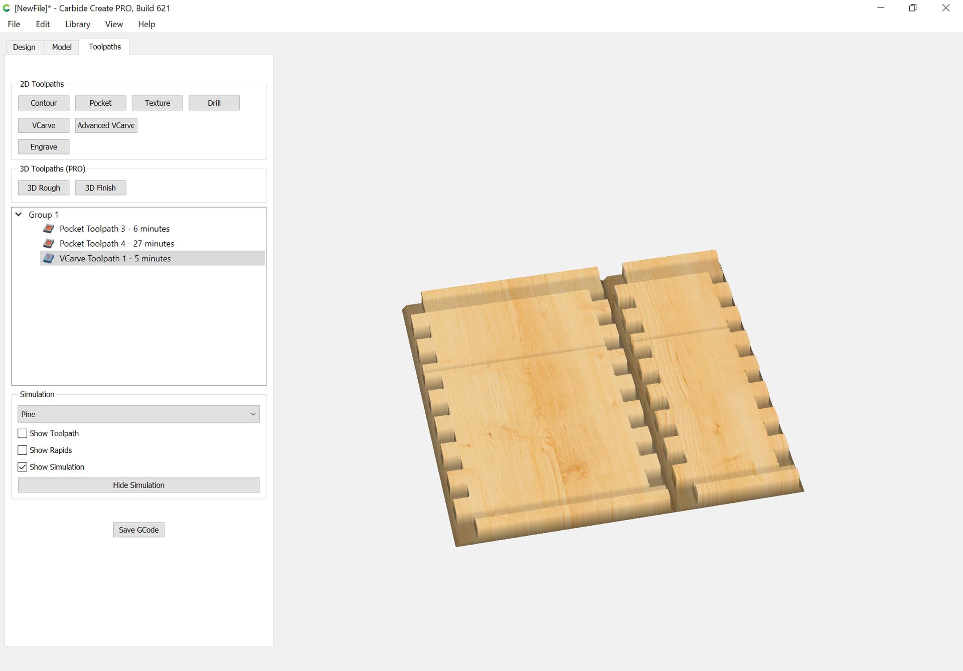
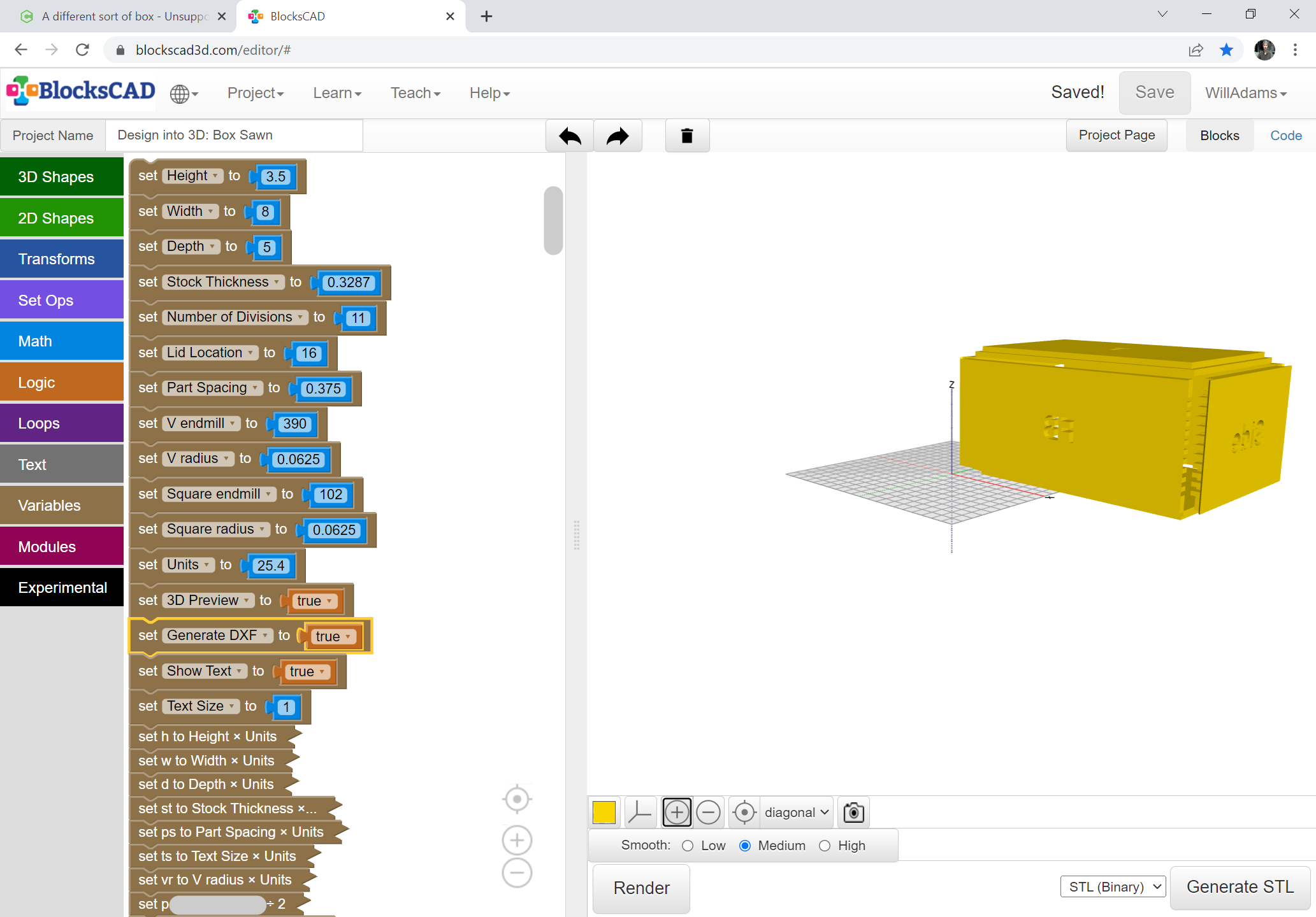
Next up, exporting to OpenSCAD, re-working the file to use the Customizer, adding quality controls, and seeing how it looks when pulled in to Carbide Create.

The OpenSCAD file seems to render well:

Blind mitre square fingers.zip (2.0 KB)

Imports as expected:

and once toolpaths are assigned, previews as expected:

This topic was automatically closed after 30 days. New replies are no longer allowed.

The above technique was used successfully to make a 20" wooden cube of 12mm Baltic Birch:

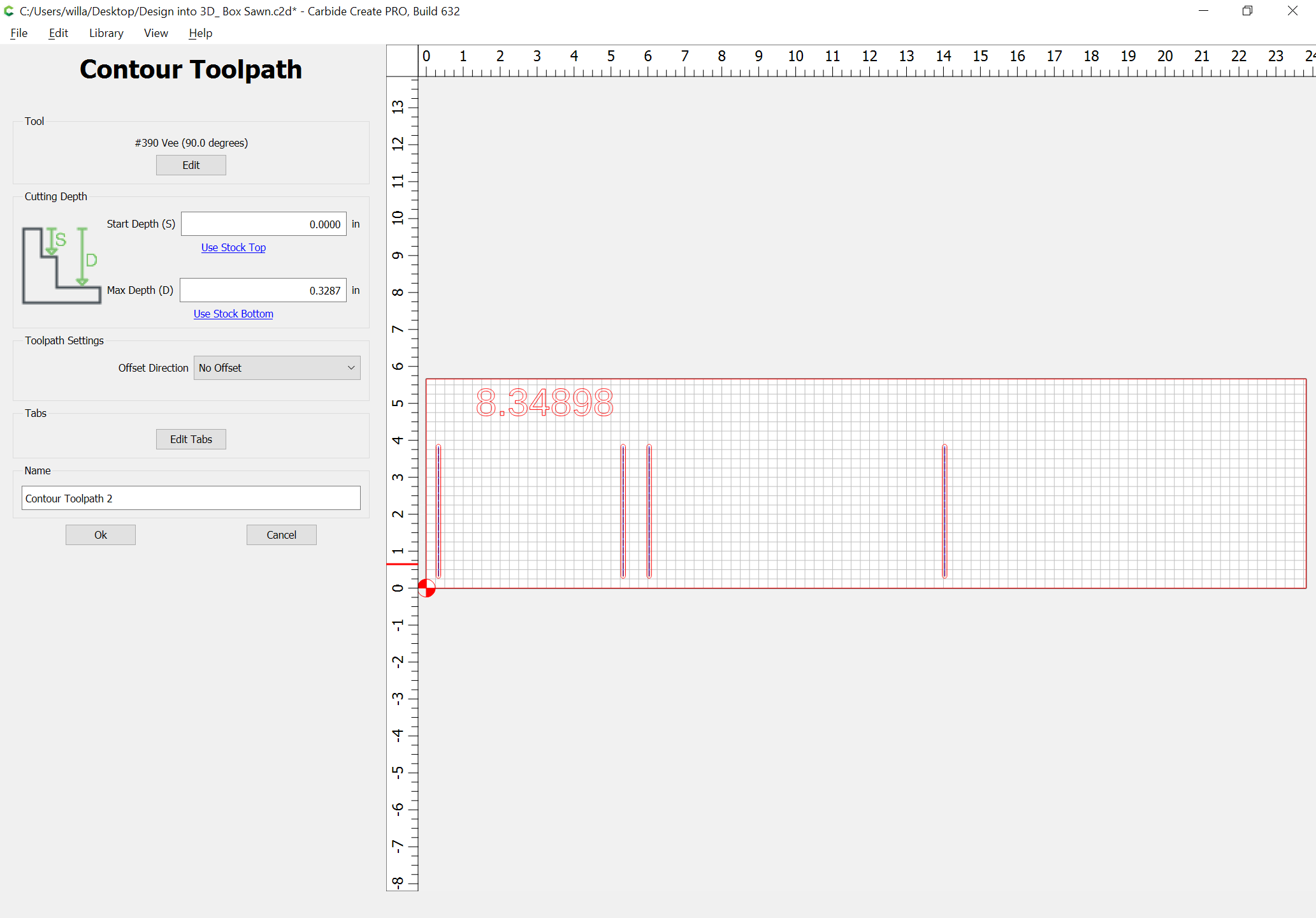
The new CC629 allowing 3D previewing of V endmills when used for contour toolpaths makes this sort of design work much easier and more efficient, since it is no longer necessary to overcut at the ends of the V cuts used for the miters.

3 Likes

Reworked the BlockSCAD file:

https://www.blockscad3d.com/community/projects/1345698

Working on getting the OpenSCAD file to make flattened geometry suitable to export as a DXF or SVG:

Success:

(improved on by adding some notes on depth and so forth)

1 Like

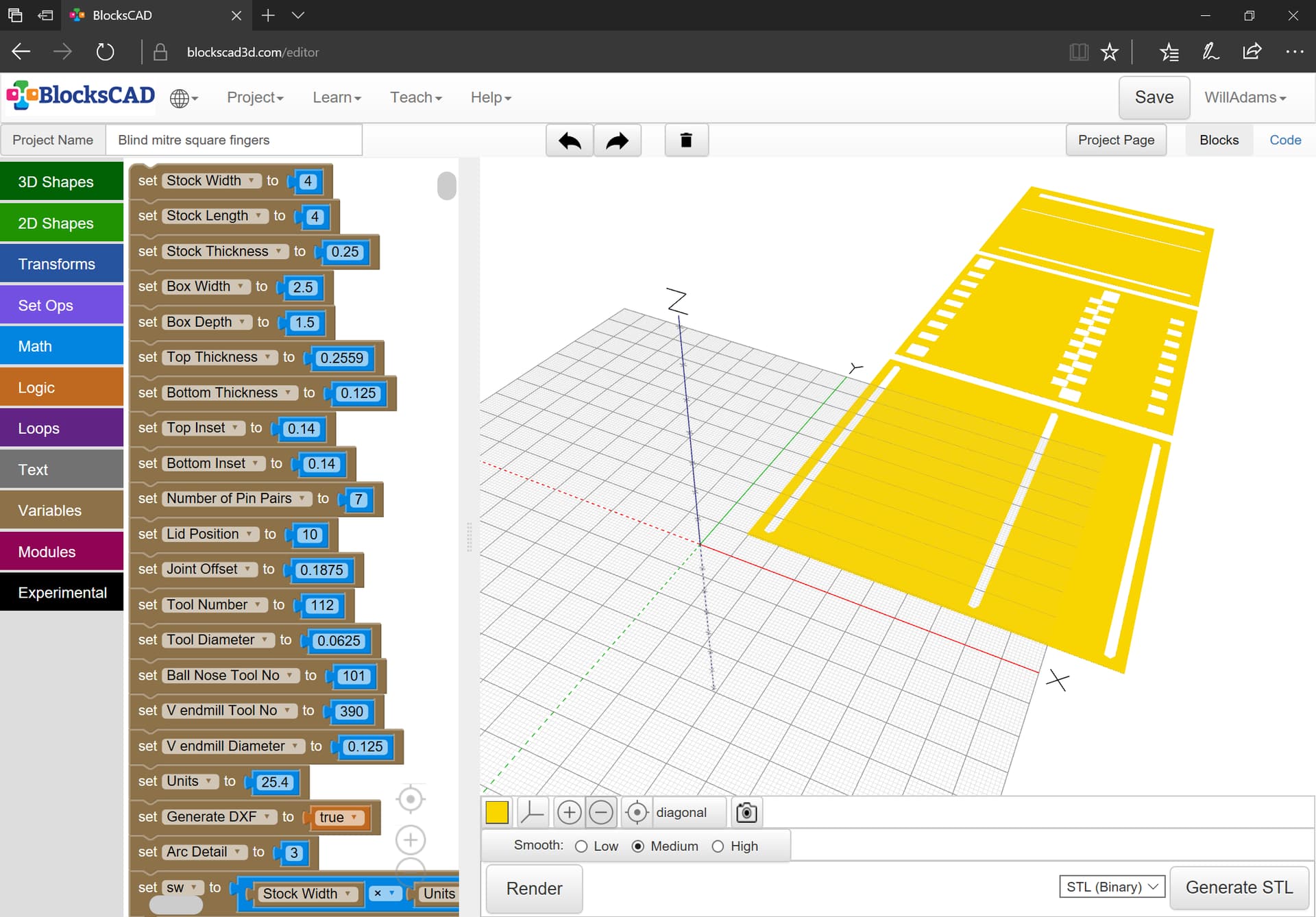
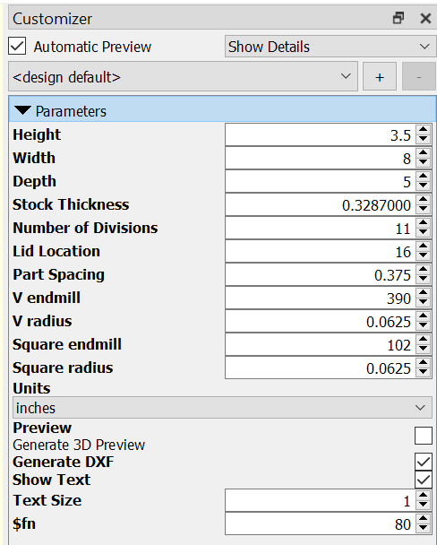
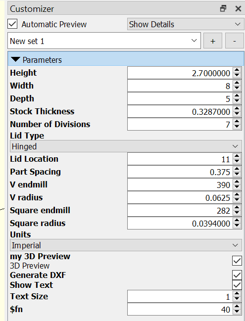
The interface allows setting the parameters or the box and defining the tools which will be used. Due to limitations in how OpenSCAD defines variables it’s most expedient to require specifying the diameter of the endmills in addition to identifying them.

Design into 3D_ Box Sawn.zip (2.3 KB)

Once the file is rendered it may be exported as an SVG or DXF which may then be imported into Carbide Create:

and each section may be grouped and aligned w/ the stock and put on a separate layer:

and then toolpaths assigned.

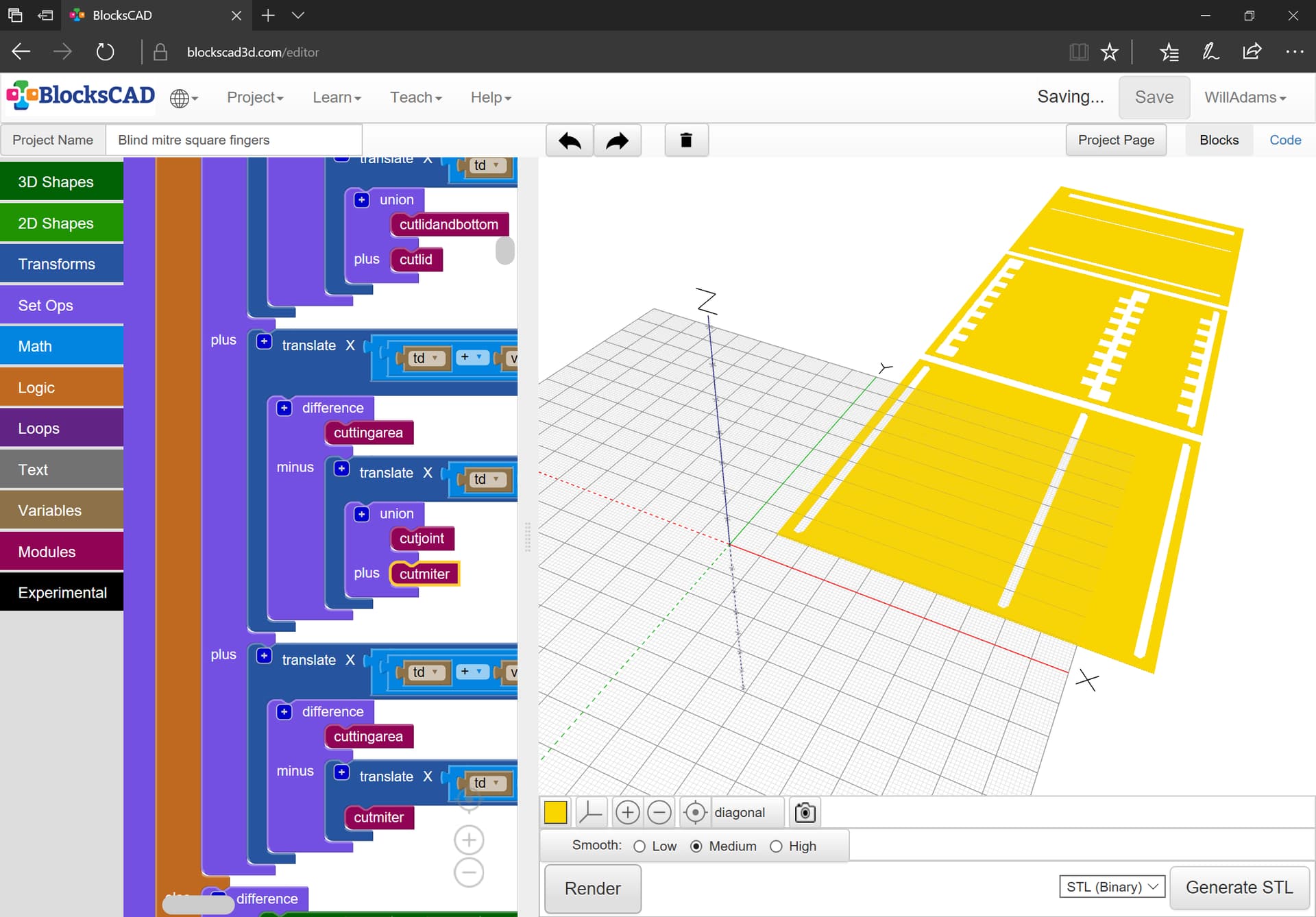
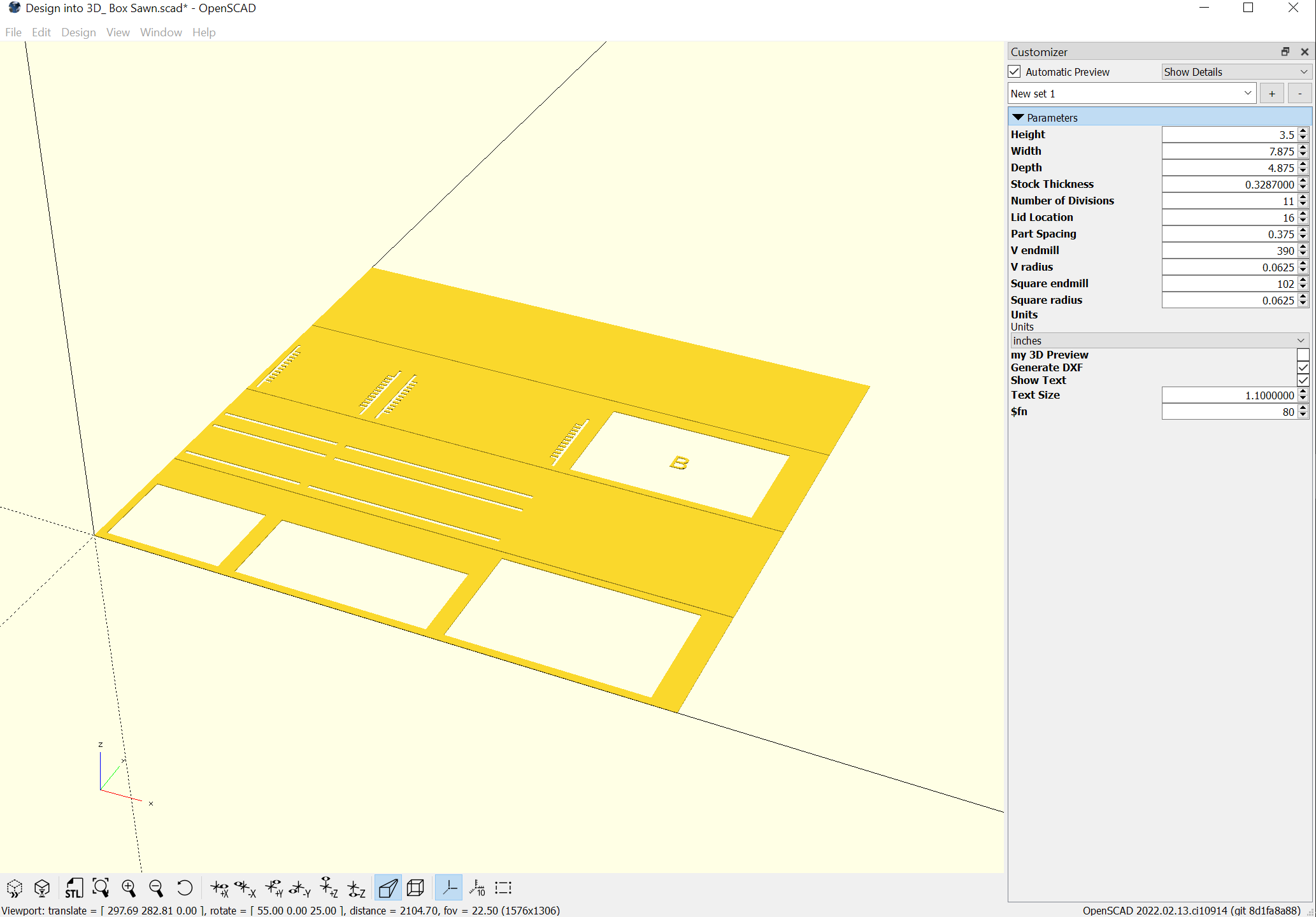
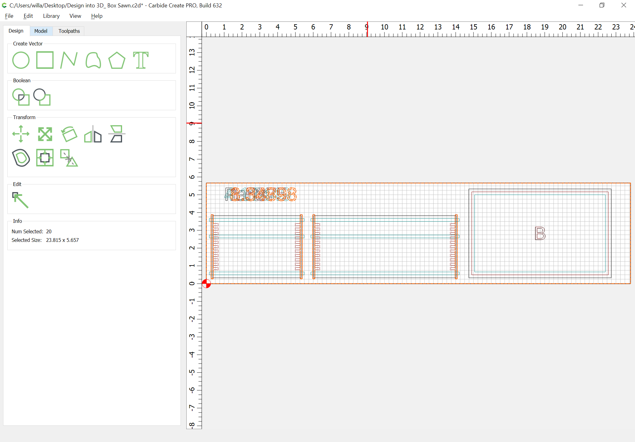
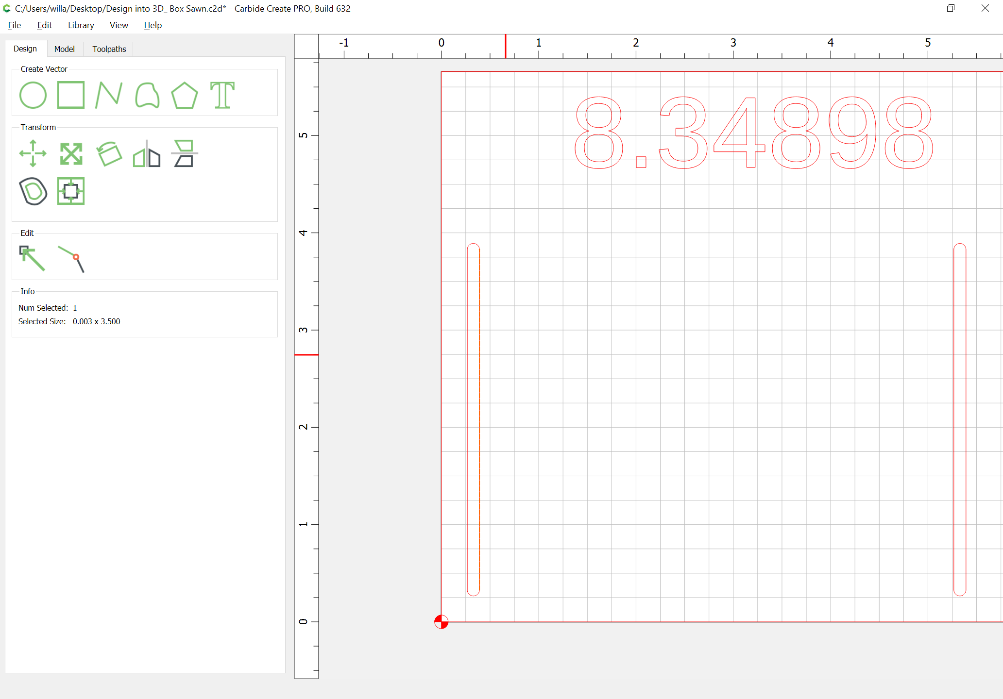
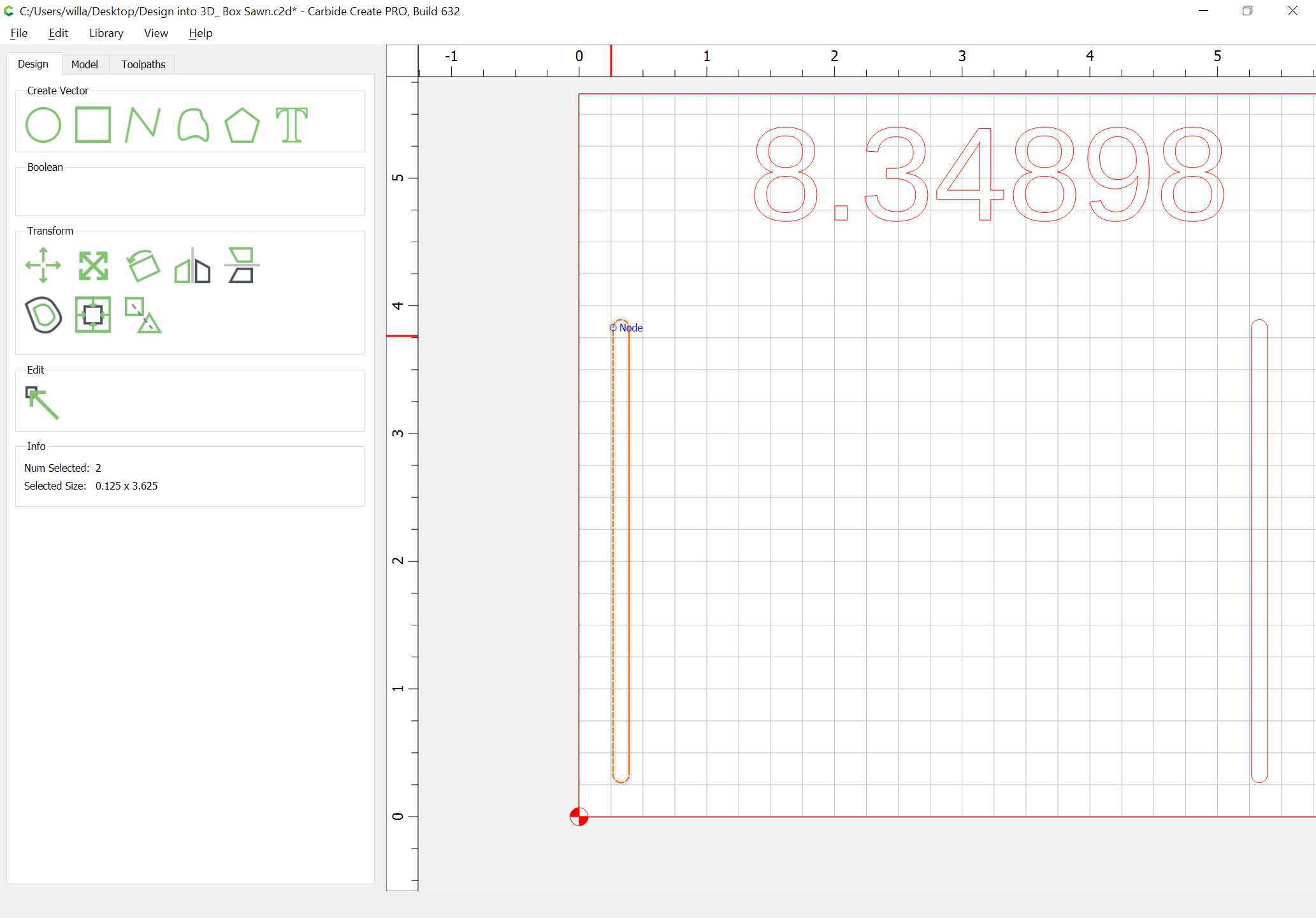
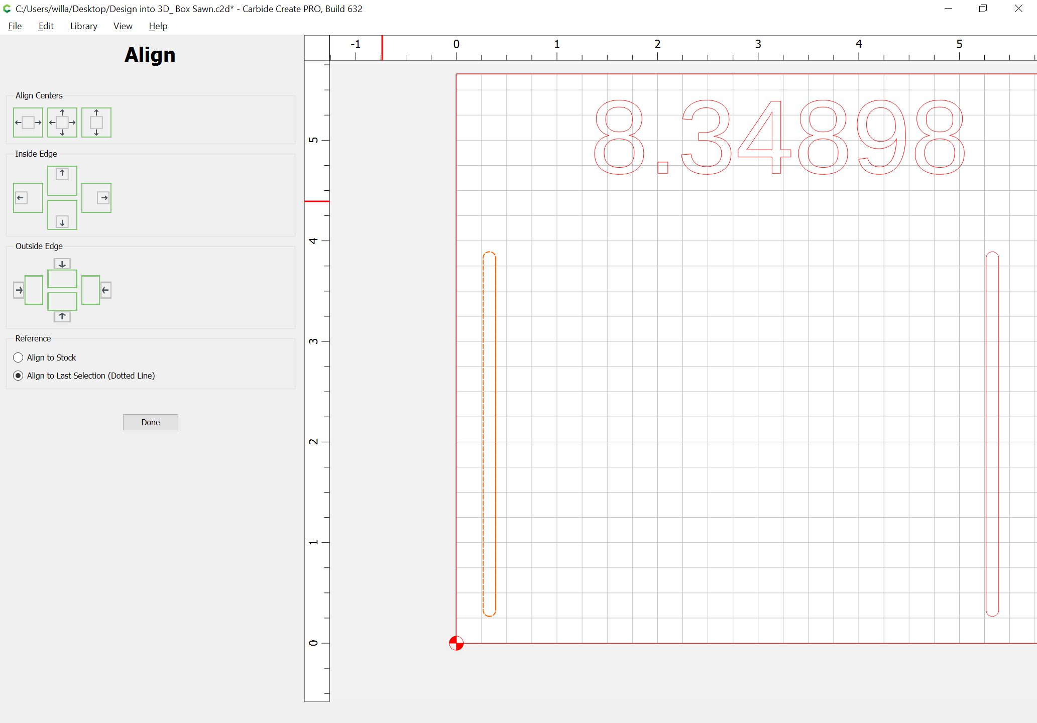
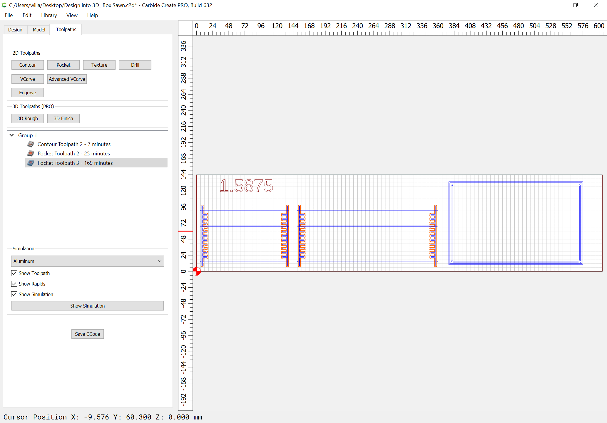
Assignment of Toolpaths is pretty straight-forward, except for one new feature in Carbide Create (assigning V endmills to Contour Toolpaths) and the inability of OpenSCAD to export an open path — for the V carving toolpaths, draw in a line for the straight lengths:

Then select the outline for the V carving as the Key object (dashed highlight):

and align to center:

(repeat for each):

Assign a V endmill to a no-offset Contour toolpath to the thickness of the stock:

Select the geometry for the rabbets and assign a Pocket toolpath to half the stock thickness:

Select the joint geometry and assign toolpaths to a depth of stock thickness minus the height of the V endmill angle:

(edit the no offset contour toolpath for the V endmill and move it to the bottom of the toolpath list and set its begin depth to that thickness)

If you are not using stock which will be perfectly sized for each part it will be necessary to add contour toolpaths to cut things out as well:

(and obviously it will be necessary to add offset geometry to accommodate this and to ensure the rabbet for the lid/bottom is cut completely)

Obviously, that was a bit off.

Optimizing for the correct geometry:

Need to lay it out for efficient use of the stock.

Updated version at:

https://www.blockscad3d.com/community/projects/1351479

and the OpenSCAD file:

Design into 3D_ Box Sawn dtb.zip (2.4 KB)

Reworked the BlockSCAD code a bit for a sliding lid option:

https://www.blockscad3d.com/community/projects/1356379

Looks like it will hide the endgrain well and still be reasonably sturdy, but it will require a bit of post-processing.

Here’s the OpenSCAD interface:

and the file itself:

Design into 3D_ Box with Lid.zip (2.7 KB)

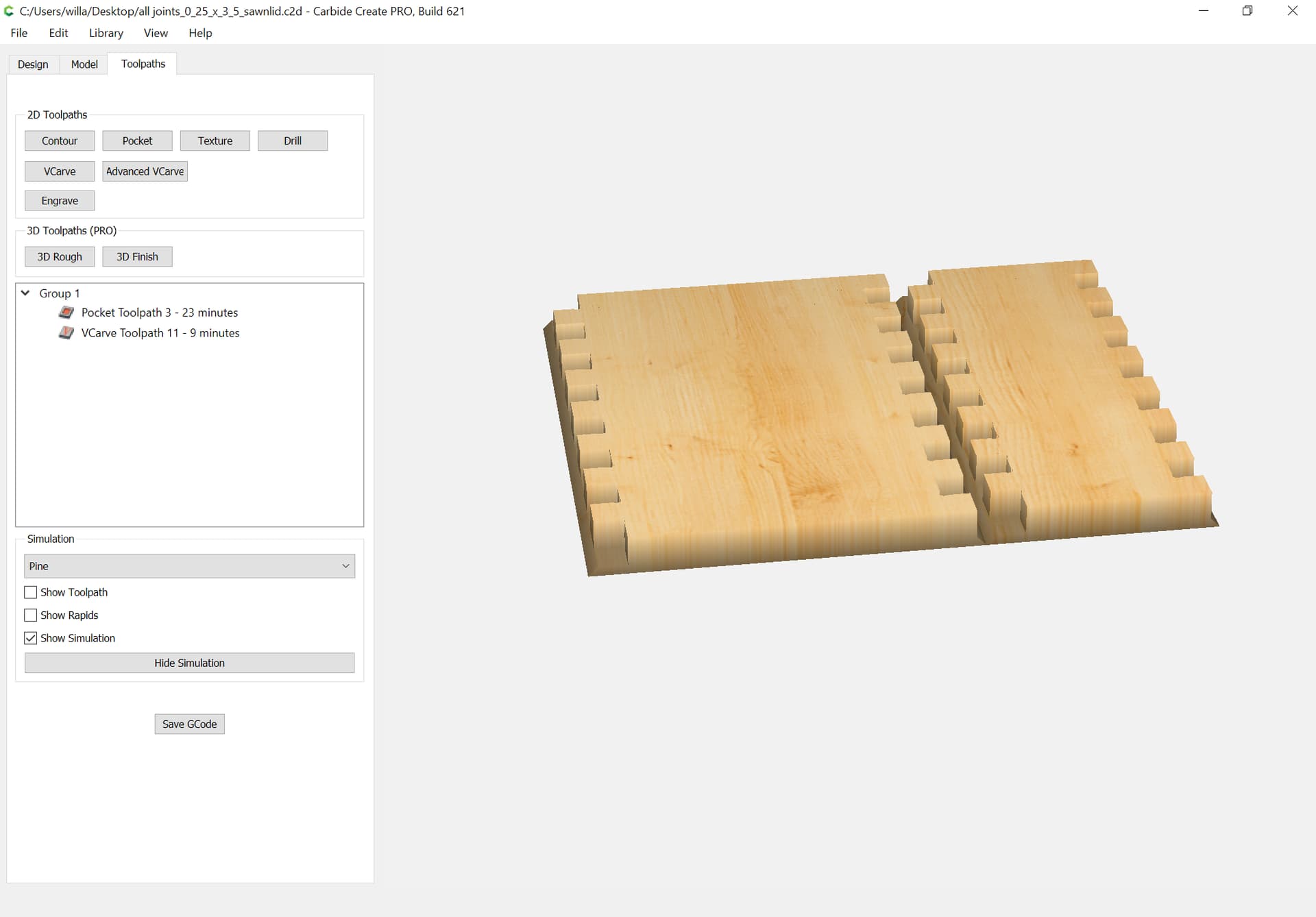
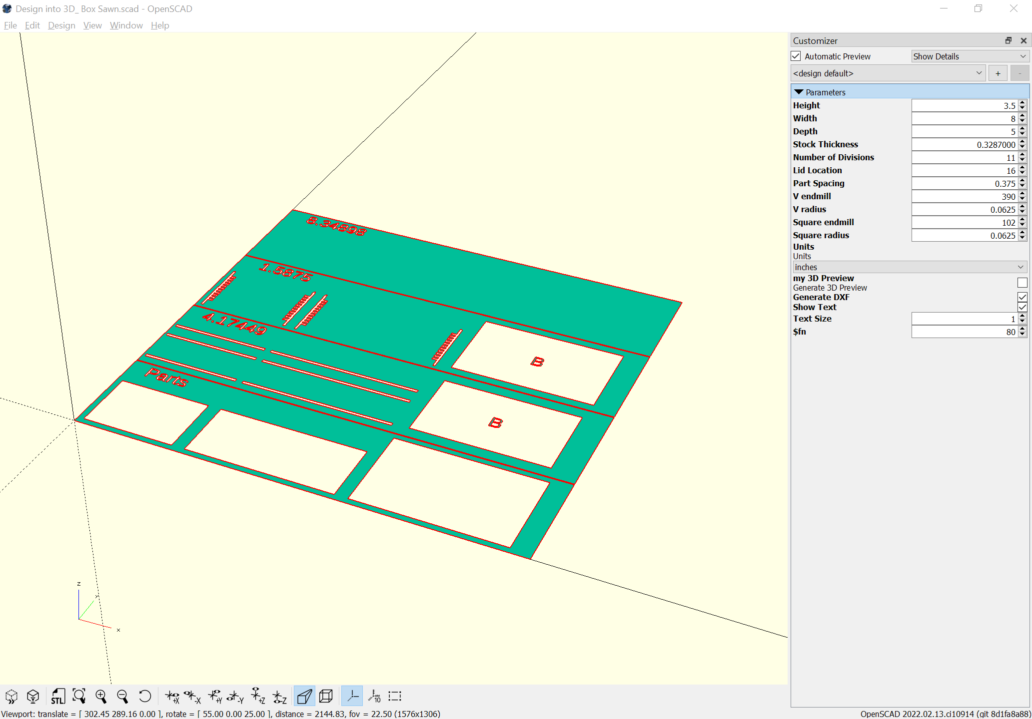
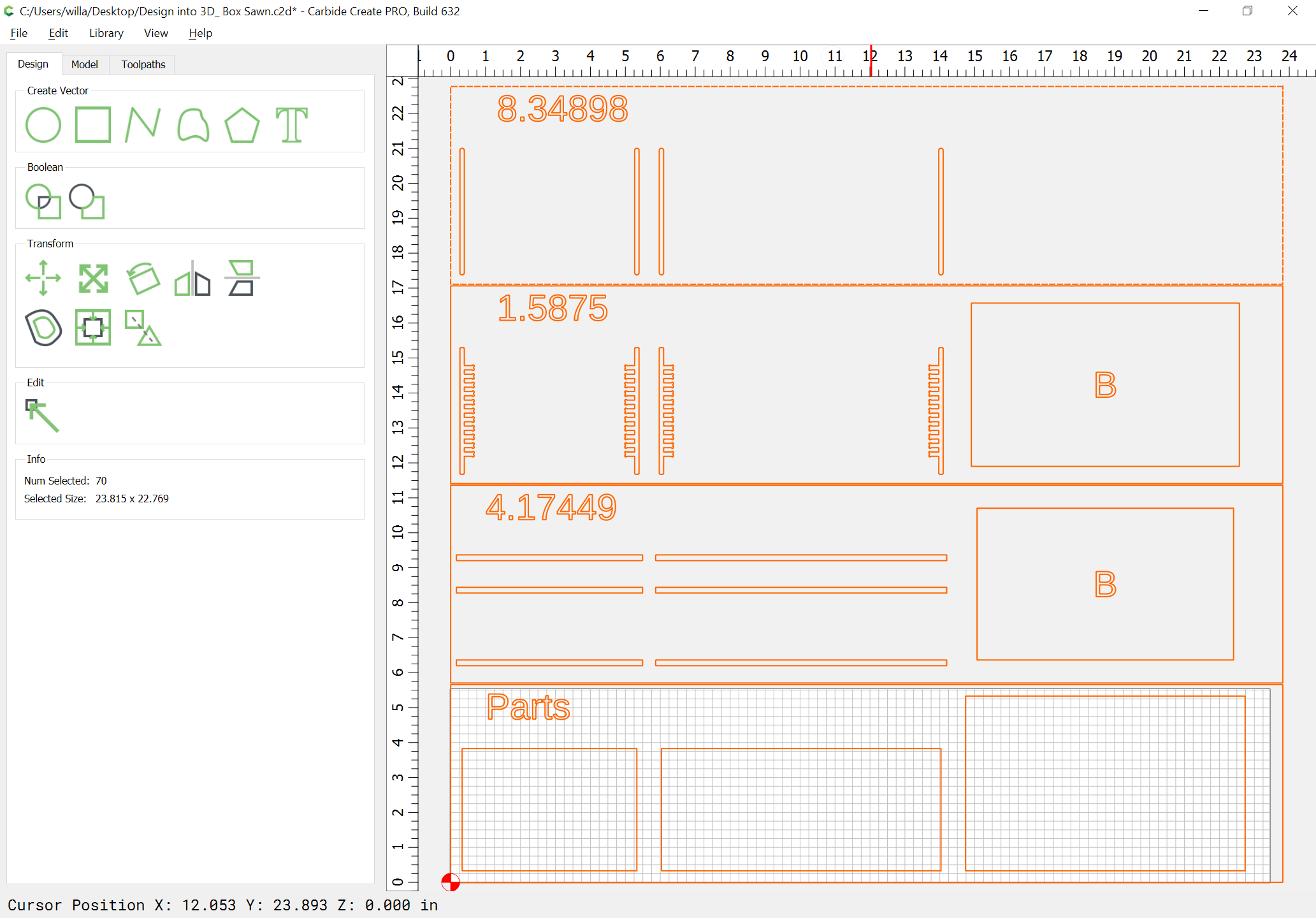
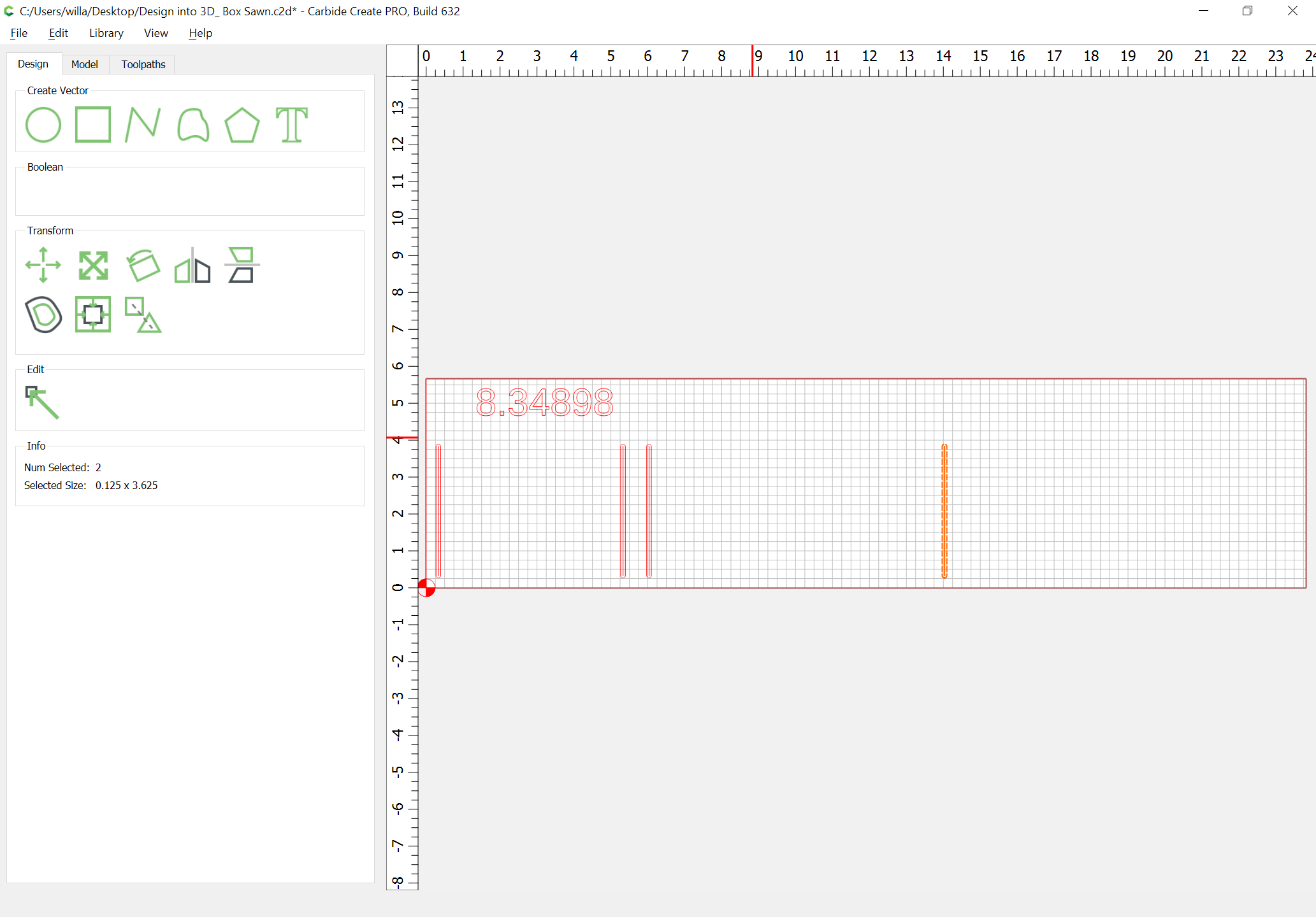
Once the file is run it will make a flattened view which may be exported as a DXF or SVG to import into Carbide Create and then have toolpaths assigned.

It wants a narrow V endmill, and I’ve been using a downcut endmill for pocket clearing and the narrowest endmill which will reach as deep as necessary to make the dogbones (the joint isn’t quite void-free):

Cutting now — we’ll have to see how things work out and fit together.

Sides cut well:

2 Likes

I hope to show how it works.

(with apologies to Mark Knopfler)

I believe I’ve worked through all the possible difficulties and complications of this sort of thing, and have a handle on an optimal solution/representation which will handle design and parameterization, features/options, layout and arrangement and export for cutting and so forth.

It would be nice if there were some better tool/technique which suited me, but perfect is the enemy of good enough and I have some 139 pages which will need to be revised based on this.

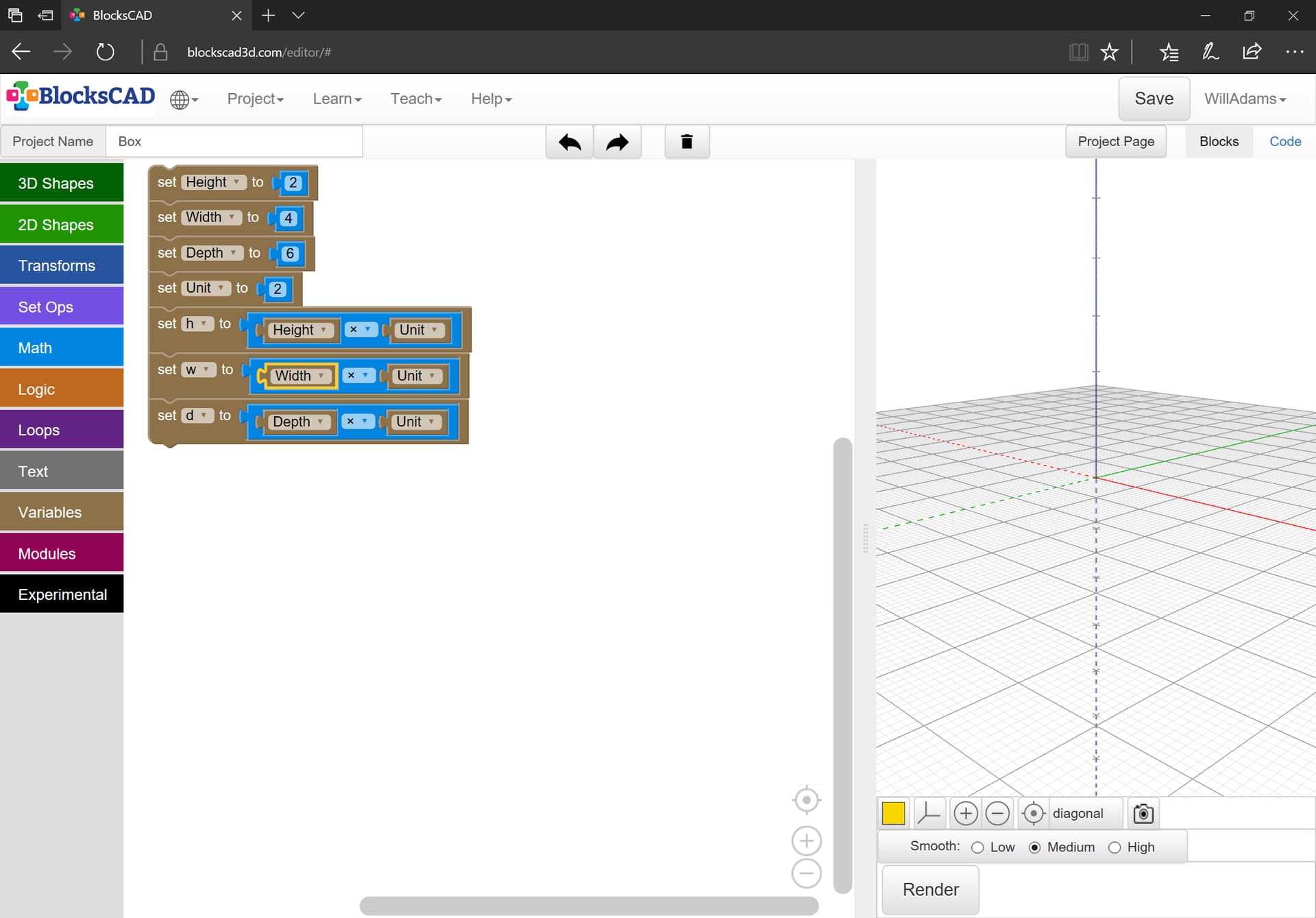
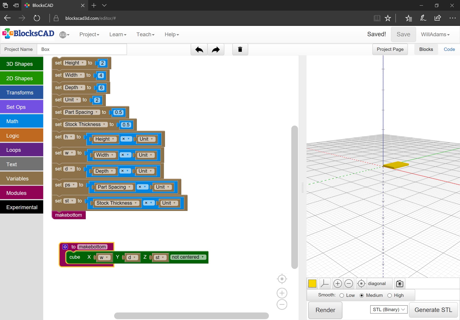
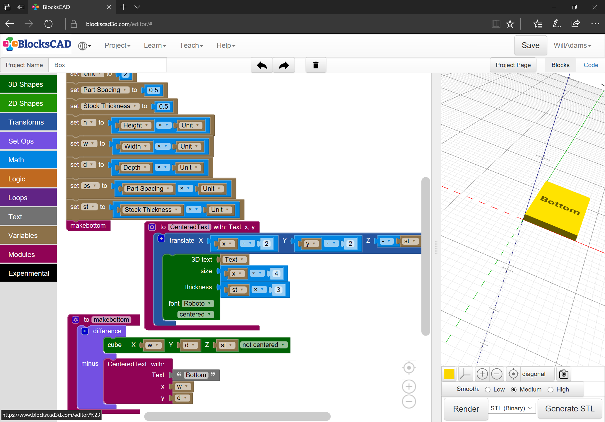
As per usual, we start in BlockSCAD with the basics of dimension parameters and units:

Since we need to represent things as parts, we need one further dimension for Part Spacing and another for Stock Thickness, and we will need modules for each part:

One consideration here is labeling the parts — fortunately, Open/BlockSCAD support text, so: