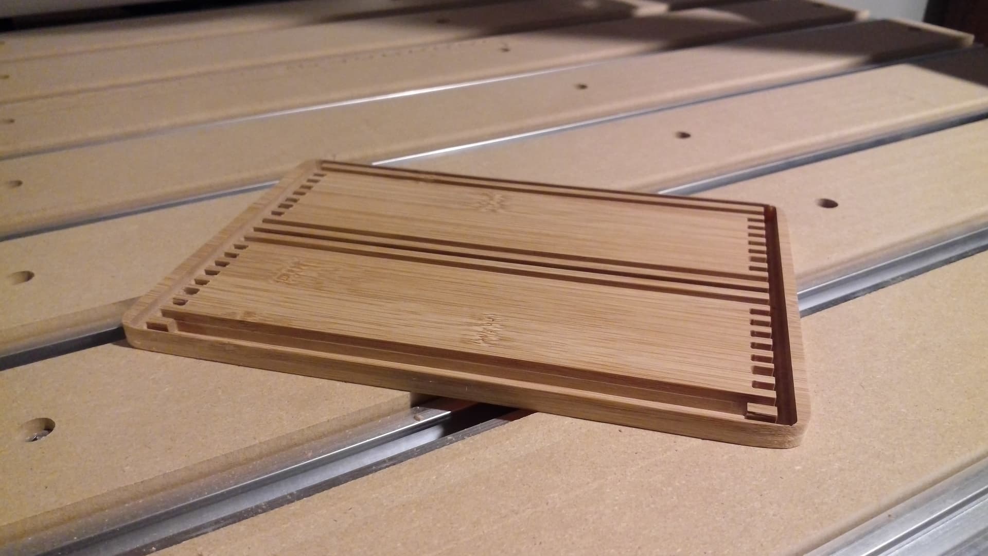
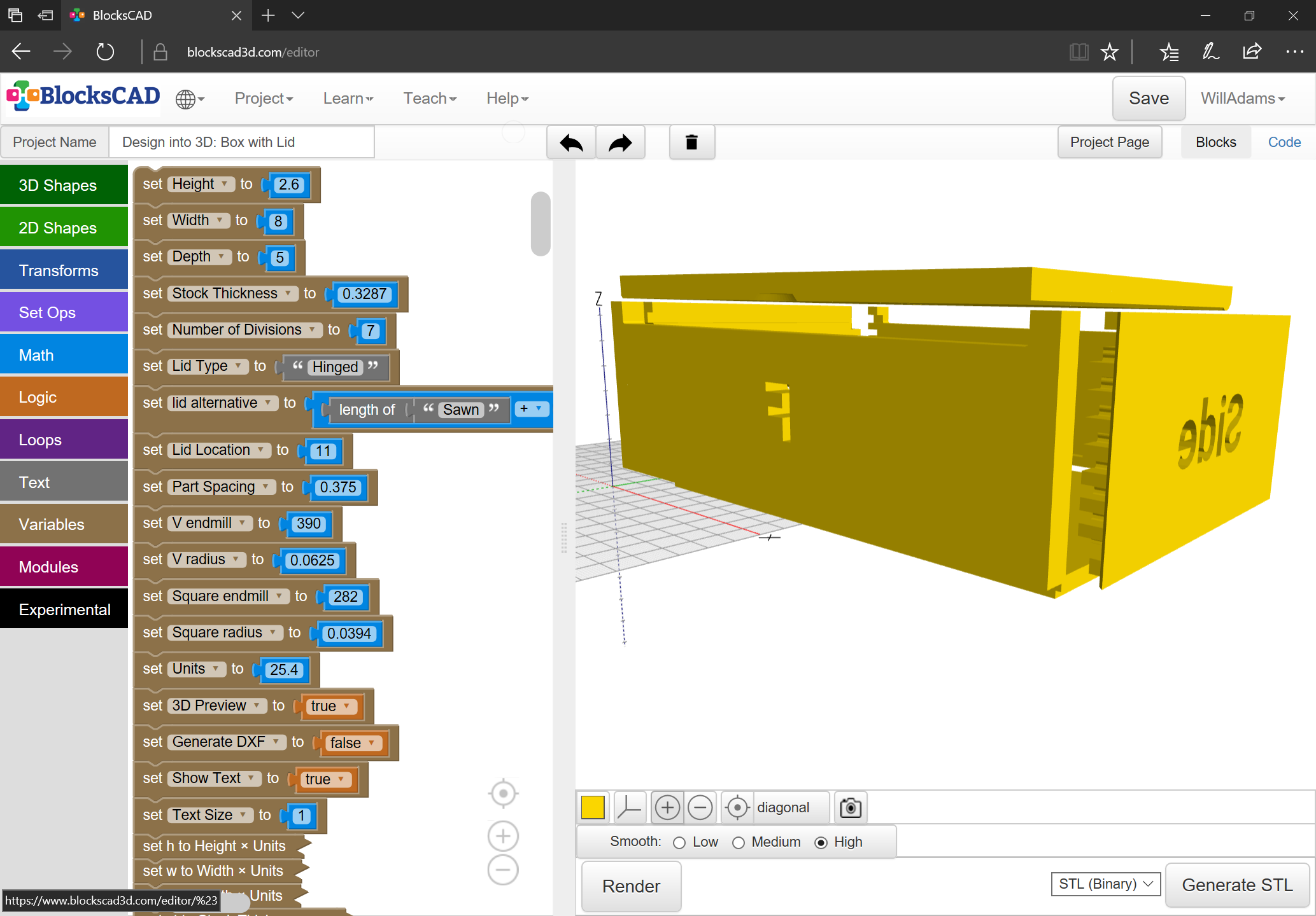
With a few additional variables we arrive at a fully labeled set of parts:

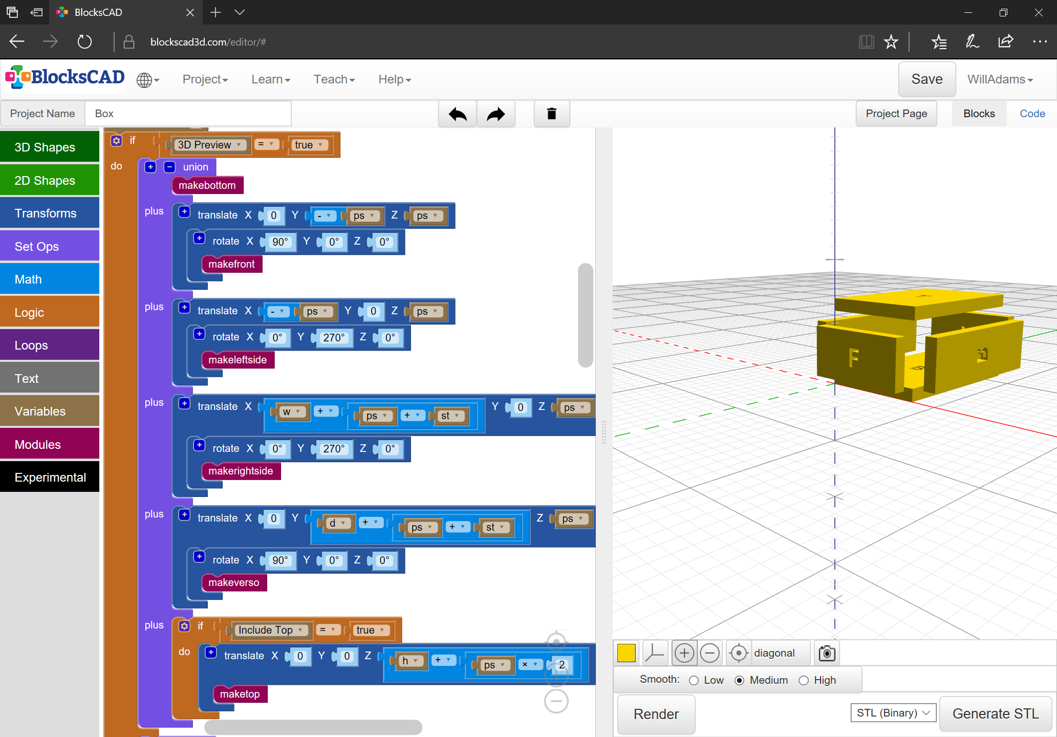
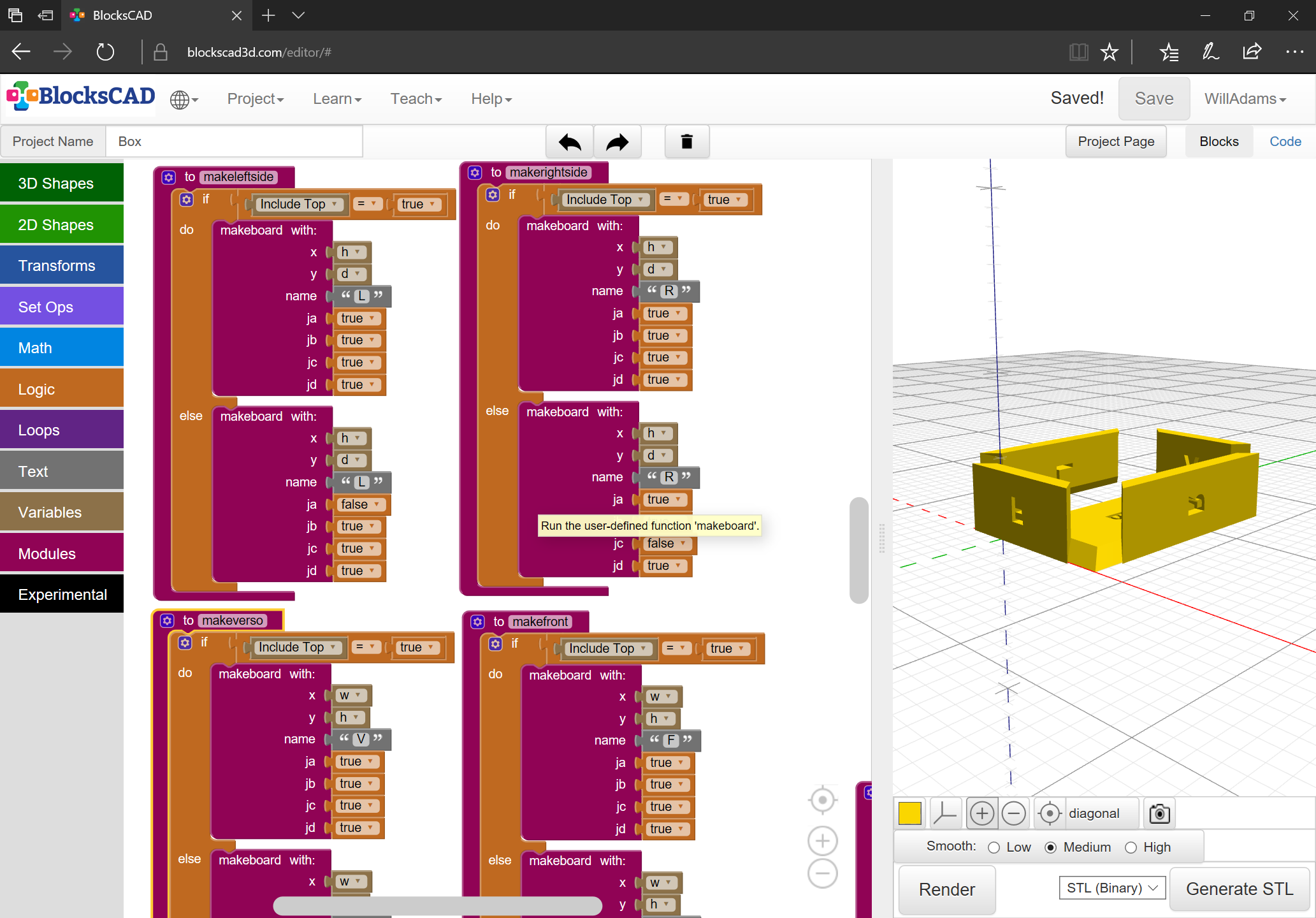
With that in place, and the V carving trimmed back a bit, we need to work out the fingers/pins — there will be 3 separate pin widths:
- vertical (for the sides going up the corners of the box)
- horizontal (side–side along the bottom/top of the box)
- depth-wise (front–back along the bottom/top of the box)
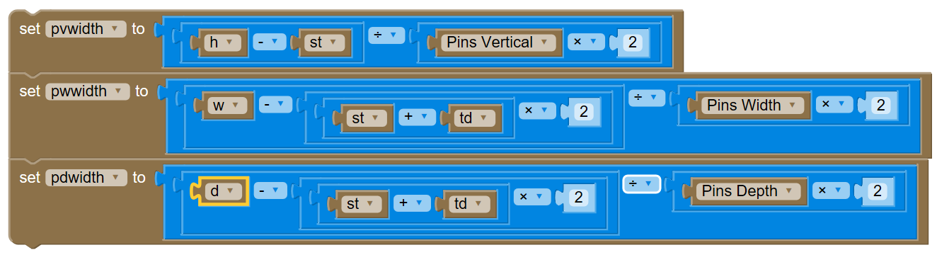
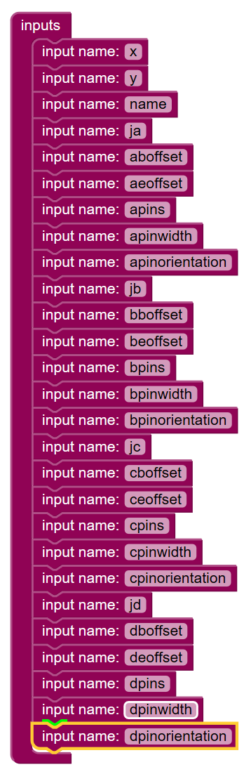
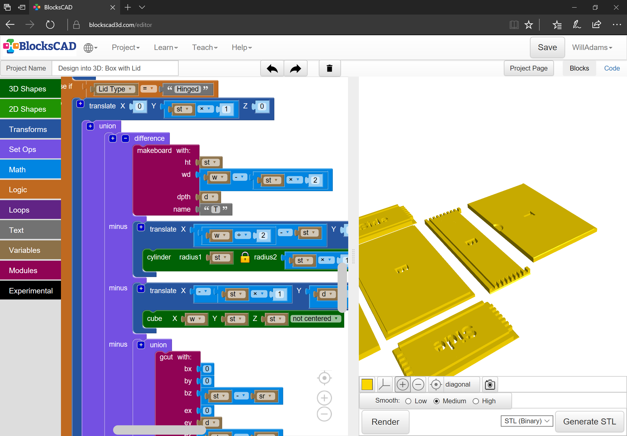
Due to the vagaries of how OpenSCAD handles variables, the most expedient thing is to allow defining the number of pins for each set of edges.

which will then require calculating the necessary width of each:
Had to recreate a file after an accidental deletion, but we now have:
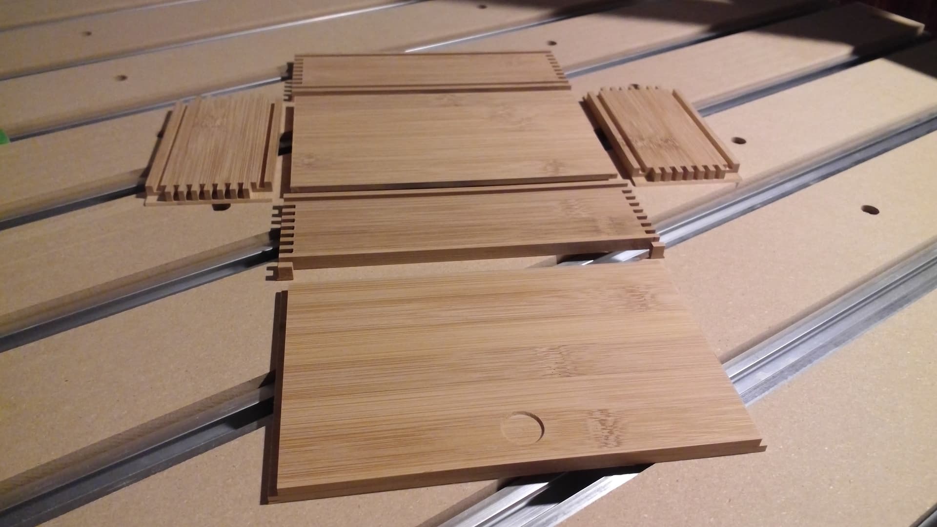
In case anyone else scored any cutting boards and wants to make a $4 (or $5 w/ inflation) box:
Design into 3D_ Box with Lid - front-back.c2d (1.6 MB)
Design into 3D_ Box with Lid - bottom.c2d (156.5 KB)
Design into 3D_ Box with Lid - top.c2d (88.7 KB)
Design into 3D_ Box with Lid - sides.c2d (1.8 MB)
7 Likes
Thanks for this Will. This box design will be something I try in the not too distant future.
If you have any difficulties working up the toolpaths, let me know.
c.f.,
for a basic tutorial.
Eventually there will be a compleat writeup at:
2 Likes
This is so cool! Well above my current wheelhouse, but really puts things into perspective on what is possible with the machine. Really want to do this in the future.
If you will let me know what stock thickness you would like to use, and what box dimensions you want, and whether you want a hinged or sliding lid, I’ll gladly work up a step-by-step tutorial for that size.
1 Like
That would be cool. We’re currently in the middle of a move, and my shop is out of commission while I build up the new space, but I’d love to take you up on it. My real question is if all the work done in OpenSCAD is necessary or if you could fully do this in CC or Fusion?
Unfortunately, it’s not workable to do all the design for CAM in OpenSCAD — it won’t write out G-Code, and it can’t do an open geometry — still looking for a CAD/CAM tool which suits me which can do these things.
I show doing this in Carbide Create alone at:
Yes, it could be done in Fusion — I think one of the links at:
shows that.
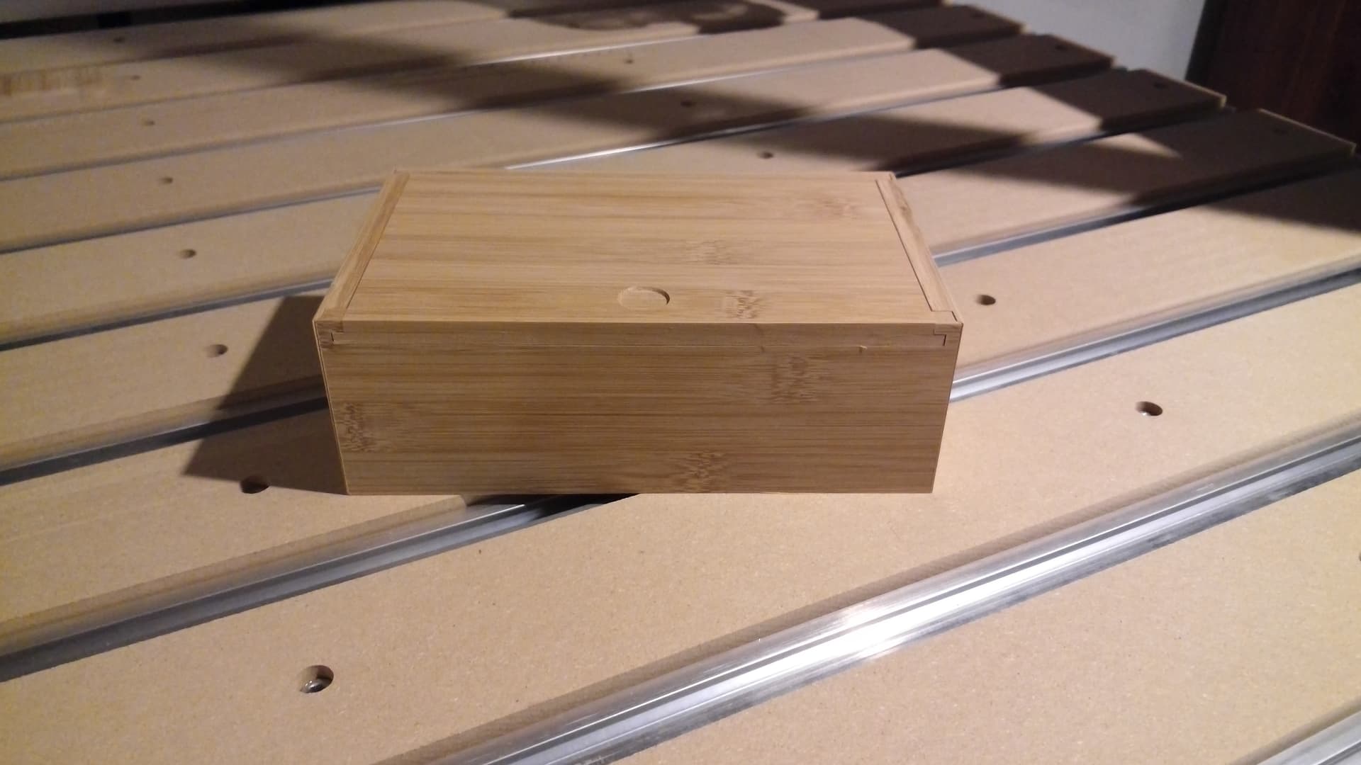
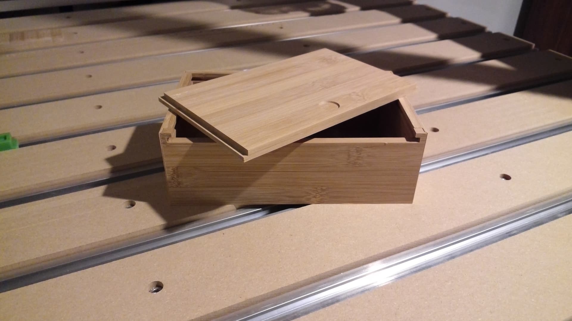
Looking at the finished box, I got to thinking about the voids which are left in the sliding version — while thinking on how to address them, I realized that it would be possible to have a minimal hinged (pinned) lid, so the previous hinged option was renamed to “Sawn” and I worked up a Hinged option:
https://www.blockscad3d.com/community/projects/1368564
It will require rounding off the back underside of the lid, but that’s easily done w/ a hand plane or via 3D modeling if one doesn’t have a suitable endmill for doing so. Also one will need to make a fixture to hold things in place while one drills for the hinges.
1 Like
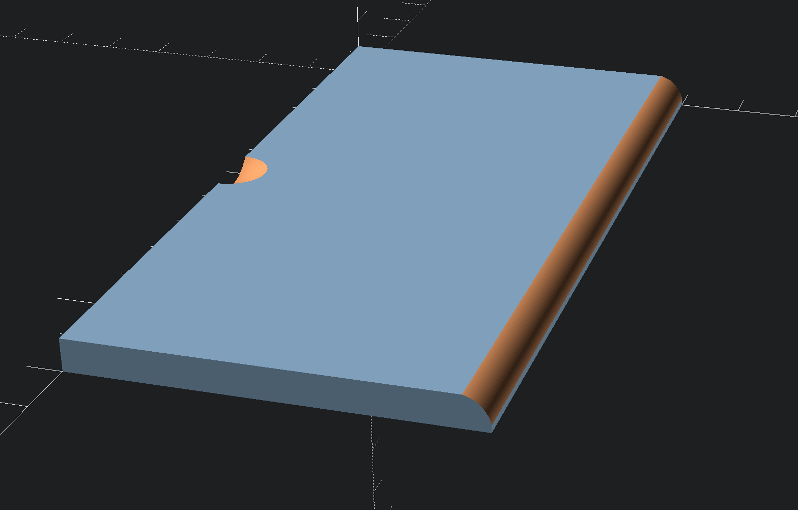
The following OpenSCAD script could be adapted to assist in creating such a 3D model suitable for this box’s lid, if that’s useful:
$fn=100;

module roundOver(radius=5,length=100) {
    translate([0,0,0])
    rotate([90,0,90])
    linear_extrude(length)
    difference() {
        square([radius,radius]);
        circle(r=radius);
    }
}

module lid(width=120,depth=60,height=5, fingerRecessWidth=15) {
    difference() {
        cube([width,depth,height]) ;
        translate([width/2,0,fingerRecessWidth/2+height/2]) sphere(r=fingerRecessWidth/2);
        translate([-0.1,depth-height+0.1,0.1]) roundOver(radius=height, length=width+0.2);
    }
}

lid();
It should make something like this which can be exported to an STL:
I did do something similar, it’s just that I rotate the design so that it couldn’t be seen easily:
The issue is I need to get this into the DXF/SVG, and unfortunately, OpenSCAD doesn’t support 3D DXFs, and I don’t want to create a requirement that folks export an STL and use MeshCAM.
I’ll probably model a cove radius tool and assign a toolpath for that as was done here:
(unfortunately, that doesn’t work in BlockSCAD for some reason — need to revisit that, and if I still can’t get it to work, file a bug report)
then if folks don’t have one of the correct radius it will be on them to model a workaround, say using the technique described at:
Ah, I see.
I thought I saw that, but I can’t access your model properly on BlocksCAD.
The sign-up/login for BlocksCAD doesn’t seem to work for me either.
The link you have shows a page with a few errors:
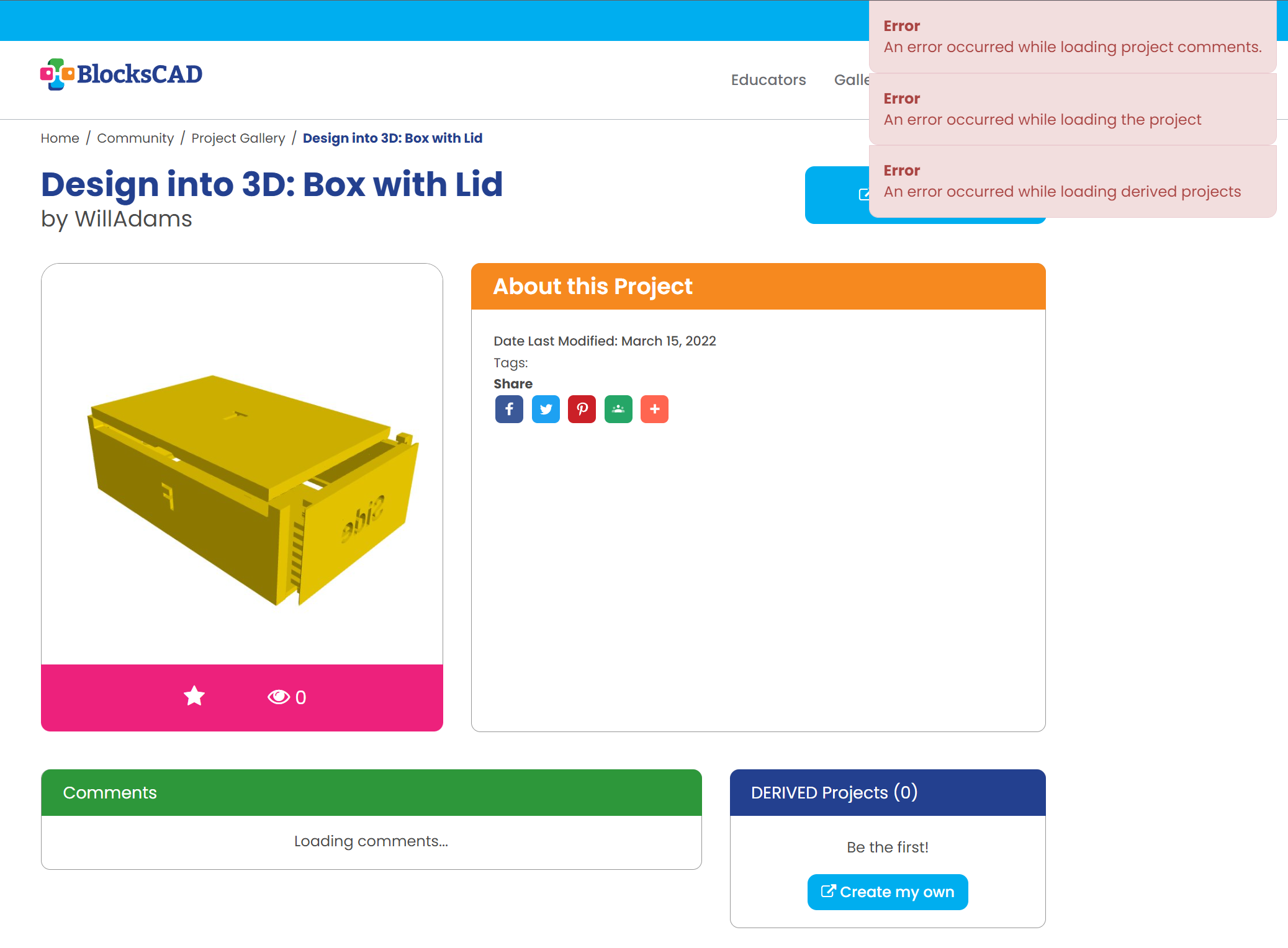
What sort of SVG would you be looking to generate from this model?
I want to get an SVG which can then be imported into Carbide Create to cut things out — see the posts above:
I had thought it was possible to edit a copy of a project in BlockSCAD — do you not get a “Create my Own” button which loads a copy?

Will have to look into that. There’s an OpenSCAD in the cloud effort which is getting started — I’m advocating for adding support for projection() and the Customizer which would make it really good for this — the only things then lacking would be the ability to do open/unclosed geometry and the ability to write out G-Code.
I have a “Create My Own” button showing, but it just loads an empty project… which is fine - BlocksCAD is not my cup’o’tea.
In the narrative above, you mix OpenSCAD and BlocksCAD in a way I don’t really follow, so I’m not sure where you leave one and go into the other.
Once in OpenSCAD you can do a projection to get the outline as an SVG (as you probably know).
1 Like