BlockSCAD has a command for exporting as OpenSCAD — once a project is done I do that, then add the code for projection() and move the variable definitions around and adjust them so that they work for the Customizer feature.
I’ve been exporting an SVG — the problem is it’s a 2D format, and OpenSCAD will only export closed regions, and there isn’t an obvious way to get toolpaths — see above where I show taking the outline of a V carving region and using it to draw a line which can then be used to do the miter instead of using a traditional V carving toolpath.
I’m stuck here because there doesn’t seem to be a 3D modeling tool which:
is programmatic
has a nice graphical interface (blocks or nodes or something better)
can write out text files w/ full user control
which has a license I’m willing to work w/ — this hybrid of BlockSCAD → OpenSCAD → DXF/SVG is the most workable thing I’ve yet found, but it doesn’t do open/unclosed geometry and there isn’t sufficient control over the echo command when writing out to the log file for one to get G-Code which doesn’t require post-processing (which is something which I don’t want to impose on the folks who use my designs).
I think we’ve discussed this before, but a fork of OpenSCAD could be bent to make some of these things happen … but then there’s maintenance and distribution of the binaries to consider. And it doesn’t have a UI with blocks and nodes (something I don’t like personally but I can see how it might appeal).
I did notice one approach recently with respects to the post processing and ECHO that reduces the skills required to grab the GCode from the OpenSCAD console to one of accurate mouse selection.
$fn=36;
mm_minute=5000;
points=[for(i=[0:$fn])let(iw=360/$fn*(i%$fn))[sin(iw),cos(iw)]];

gcode=function(i=len(points)-1)i==0?"\nG91; relative positioning\n":
str(gcode(i-1),"G1 X",points[i].x," Y",points[i].y," F",mm_minute,"\n");

echo (str("G-code:\n",gcode()));// here the code is displayed within console window
polygon (points);// not needed for the code - just to view
(edit: the basic idea here is to fill an array then render the array as GCode in one hit)
(edit2: I recently looked at the export code for OpenSCAD (they added a few more export formats) and thought it would be possible to write a “slicer” exporter that generated SVGs for horizontal layers of the model, perhaps only writing them when they differed. That would be pretty useful)
(edit3: something that did something like this: SliceCrafter )
I’m currently writing out separate layers as noted above, and have been programming the various parts modules so that they have parameters for tool and depth.
The array idea is interesting — I’ll have to look into it — found it at:
EDIT: looking into it, I don’t see how it could generate code which would work w/ Carbide Motion/Grbl — if I understand it correctly, every line will be preceded by:
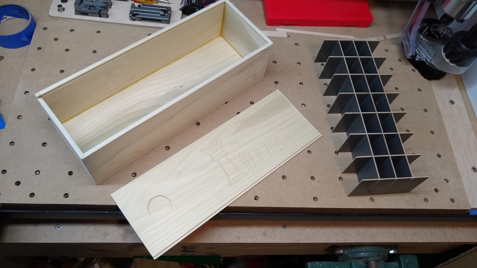
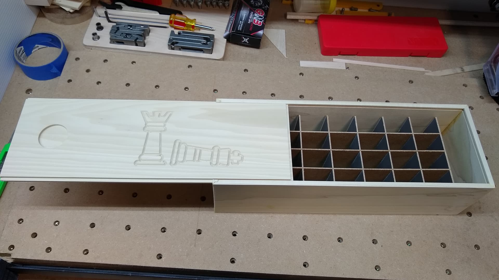
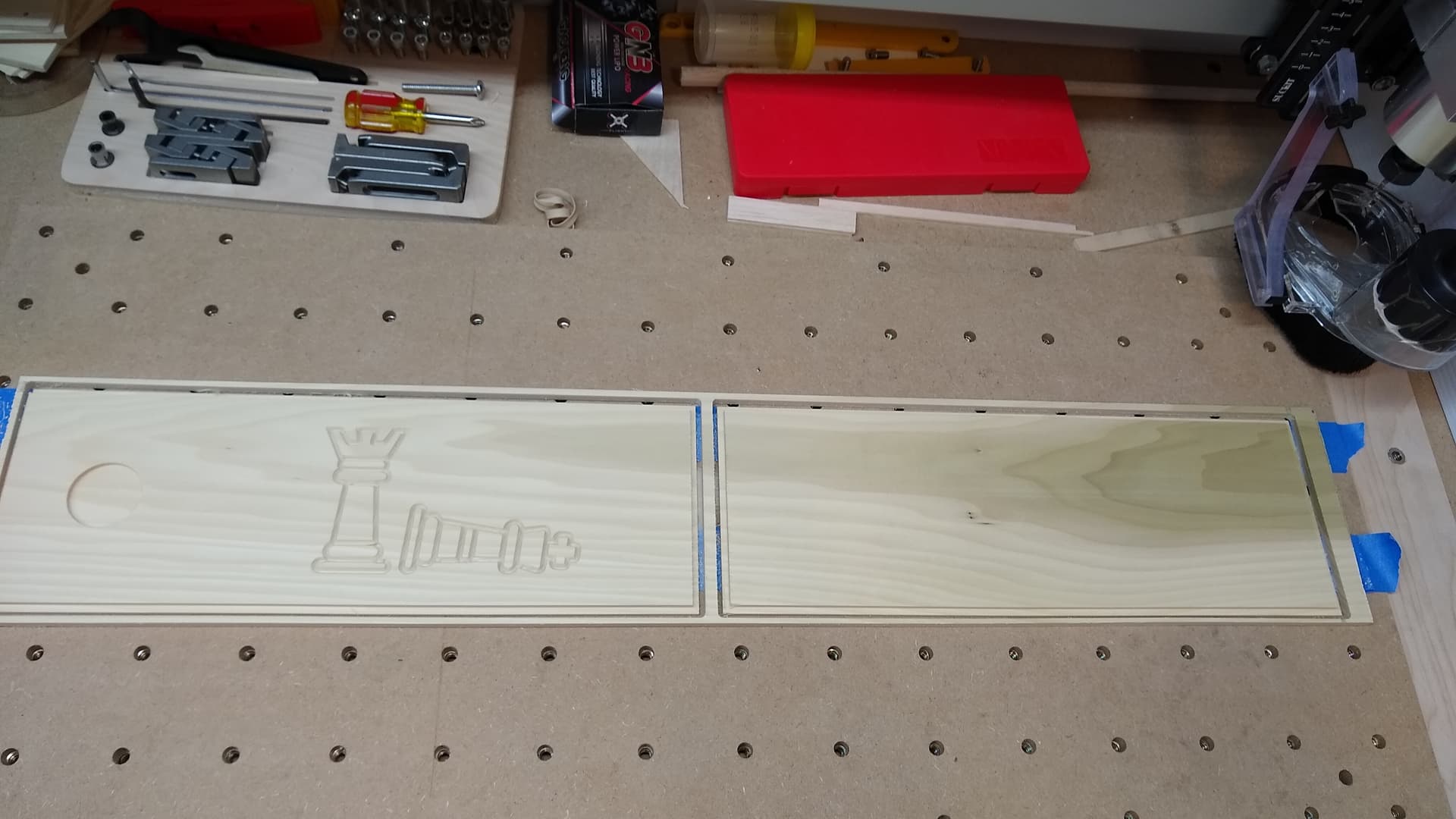
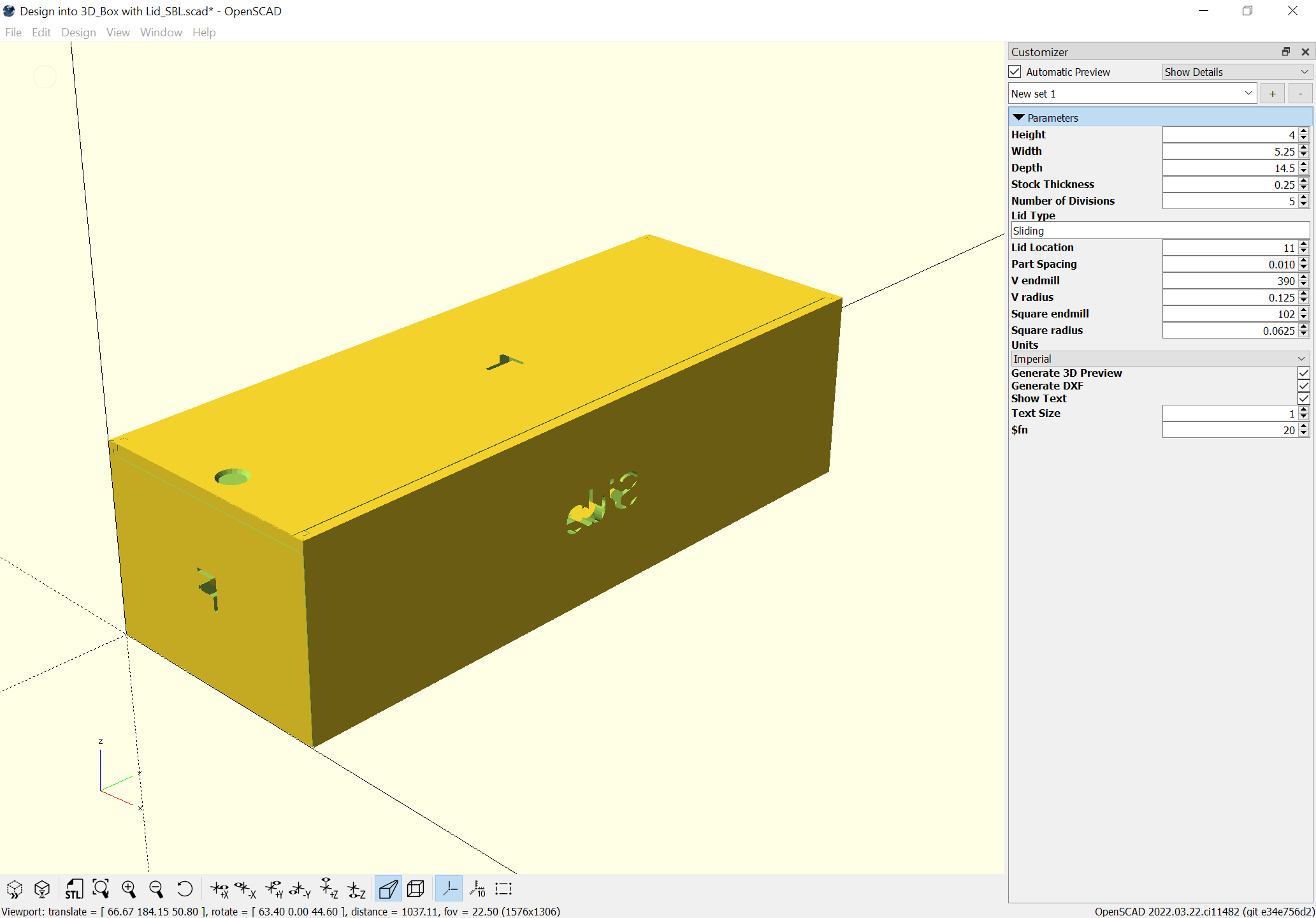
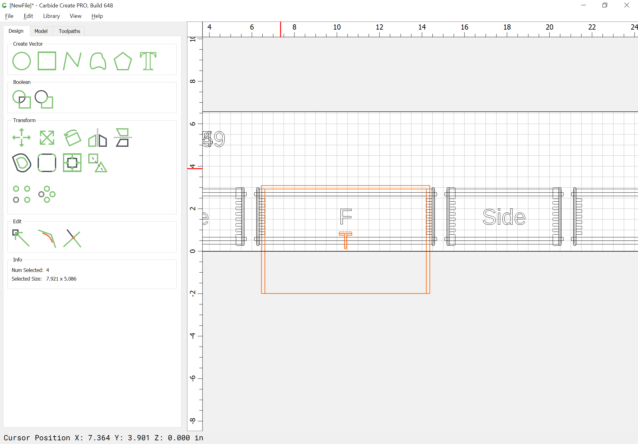
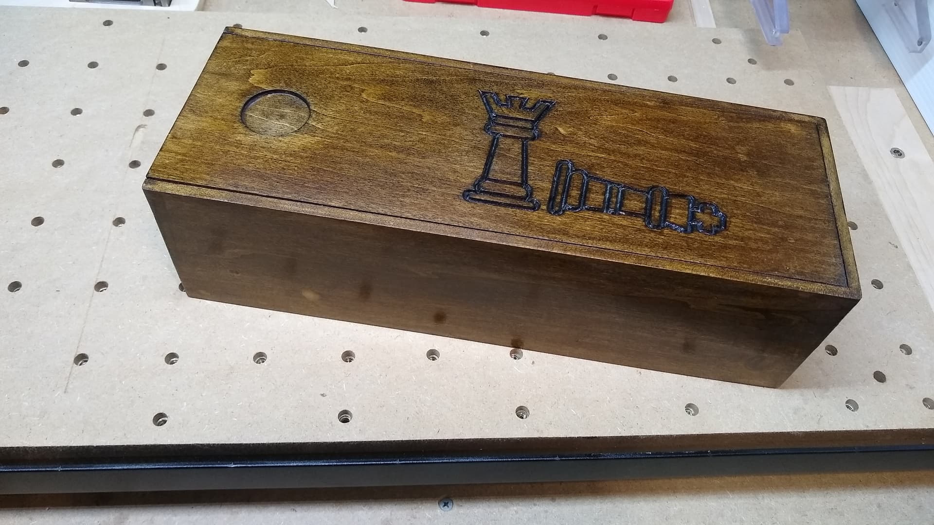
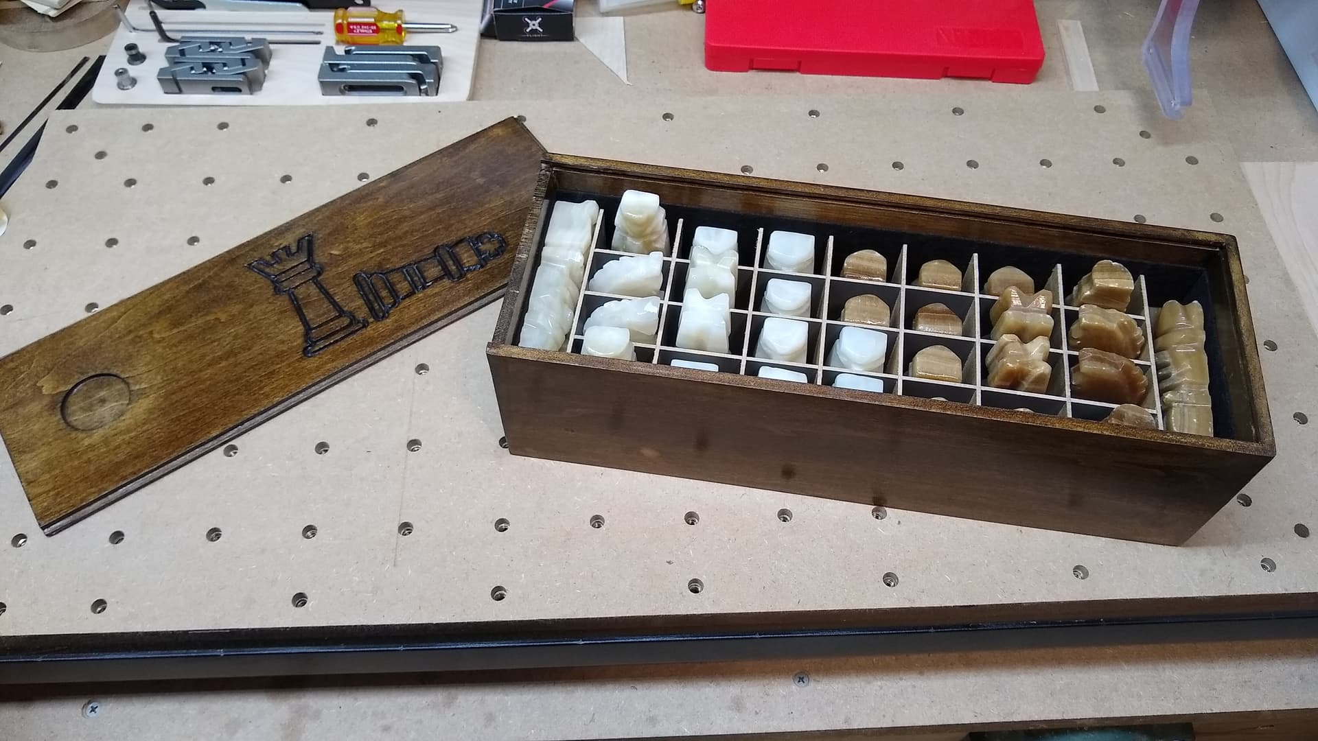
Again, thanks for your work on this. I used your OpenSCAD file to create a box to hold Chess pieces for my daughter’s boyfriend. This one is 4 x 5.25 x 14.5 inches using 0.25 thick popular. I used the SVG output to import into Carbide Create to create the tool paths. Everything worked out well, but the sliding top was slightly sized incorrectly. It was 1/8 short on both sides and 1/8 too long in the opening direction. Easy fixes, but I am not sure why that happened.
Which file did you use? What settings? Did you save them as a pre-set? If so, send the .scad and .json file to me in a PM (or post here)
Let me know and I’ll do my best to puzzle out where things were off.
Note that on the most recent version I’ve begun explicitly modeling all the pieces, where before was trying to only do the ones which were strictly needed.
I started with the last scad file you posted (Design into 3D_Box with Lid.scad) I’ve attached my file with only the new dimensions entered and the SVG output. The lid seems slightly wrong to me…
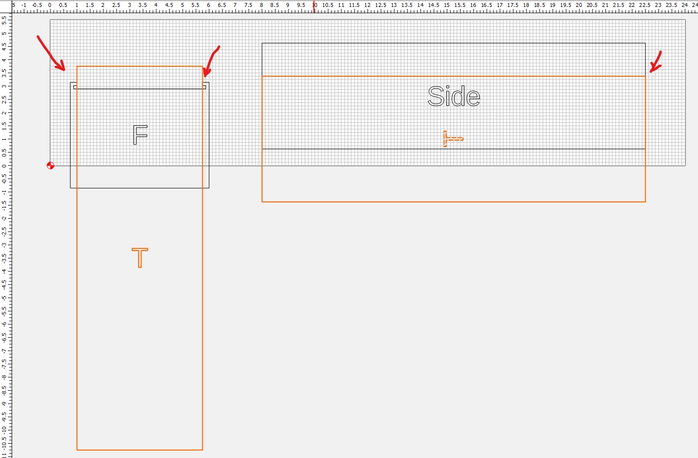
Hi Will, It still appears that in the SVG output the top size is wrong to me. I used the latest scad file with the dimensions I used earlier and the top in the parts is not correct. Shouldn’t the top width include the notches and it’s too long by 1/2 a wood thickness as well? These are from the parts area. I agree with you that the 3D render looks correct. Just the 2D output is wrong.
I’m going to document and review the code first chance I get, and will try to make it a bit more efficient about generating/not generating the rabbets and their sizes, trying to reduce voids.
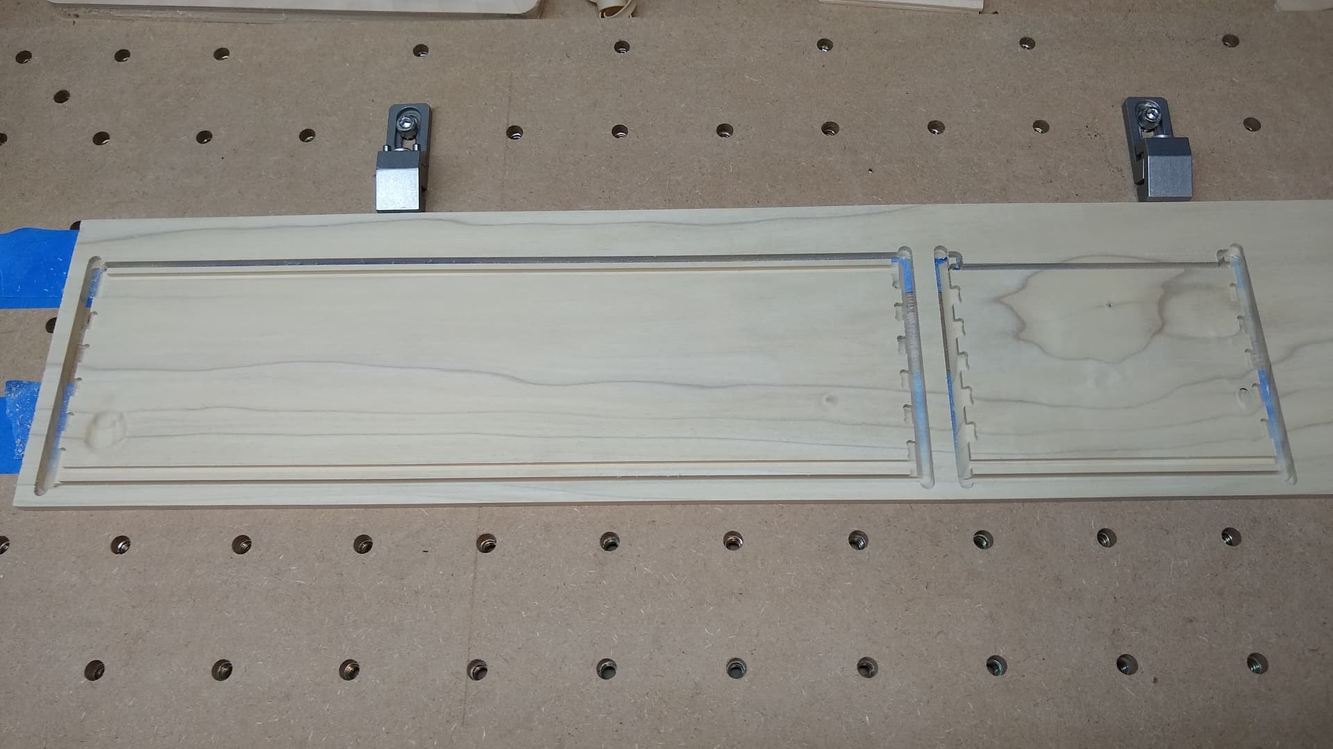
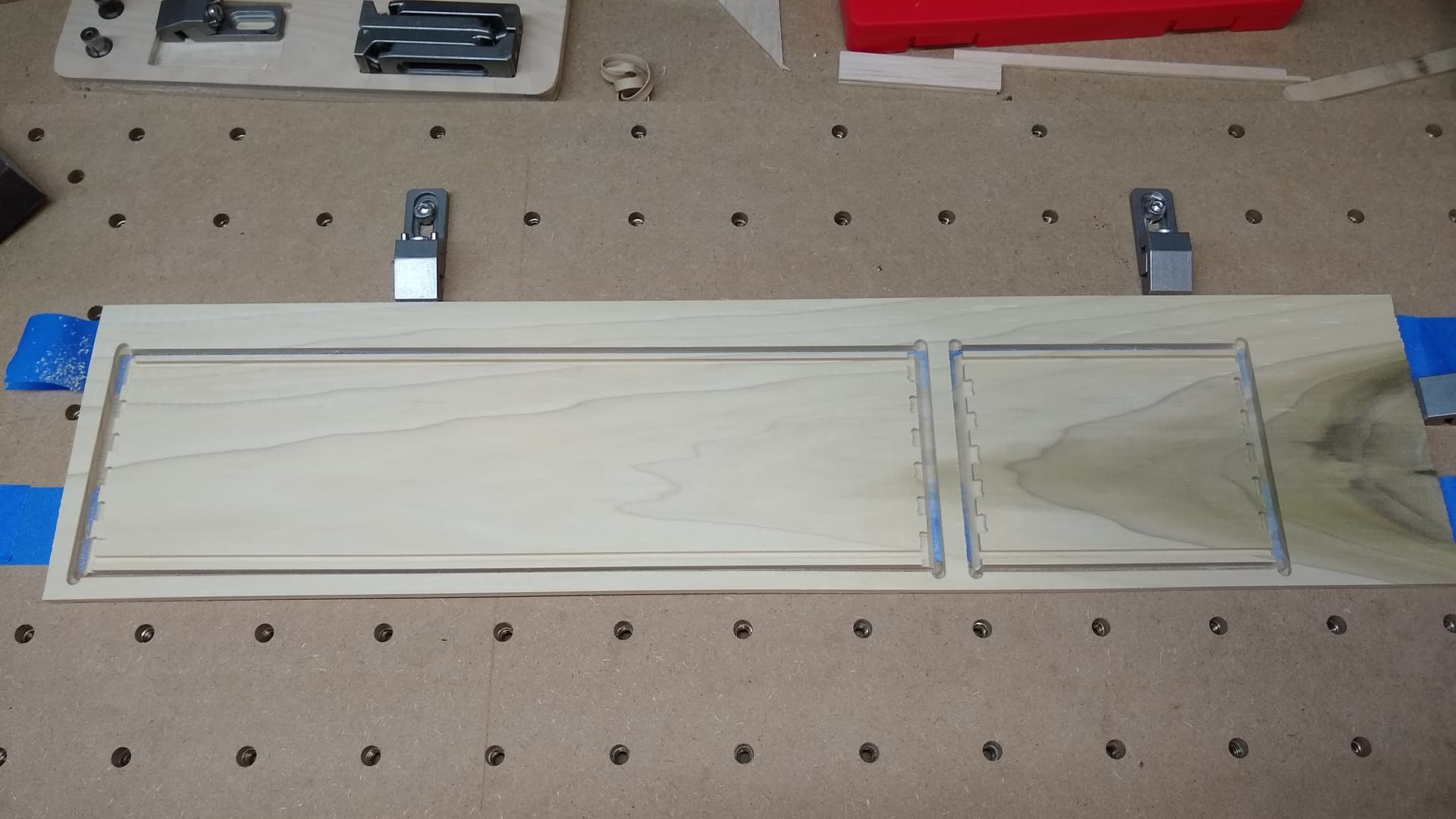
Really surprised (and pleased) that it worked when the V endmill diameter was the same as the stock thickness.
Yes, the V endmill has a radius of 1/8 inch which is half the stock and that’s what I cut off with it. It’s the smallest 90 deg bit I have.
I finished the box with a Varathane water-based stain and then some gloss water-based polycrylic. It’s the first time I used a water-based stain and it worked well. There aren’t as many color choices as oil-based stains, but there is less odor and you just need water to clean up. I also added self-stick felt to the inside of the box to protect the chess pieces. Overall, I like how it turned out and I think it’s strong enough with the mitered/beveled joints to hold these rather heavy chess pieces.
I am intending this for Will. I was trying to see how far I could get with the box generator. I was playing with it and was getting god results in BlocksCAD. I exported it into OpenSCAD and ran into a snag. I used your most recent link from this thread.
When I import the model into OpenSCAD I come across some syntax errors. Two of them are pretty easy to figure out. A semicolon was used in place of a comma in two places. I get a ton of warnings on this line code (see below) and I can’t get it to render.
Yeah, that’s a problem w/ BlockSCAD — need to report that and a couple of other issues.
Try the OpenSCAD file at:
In addition to the bug fixes it is wired up to use the Customizer feature and has the projection() command set up to work so that you can export a DXF or SVG.