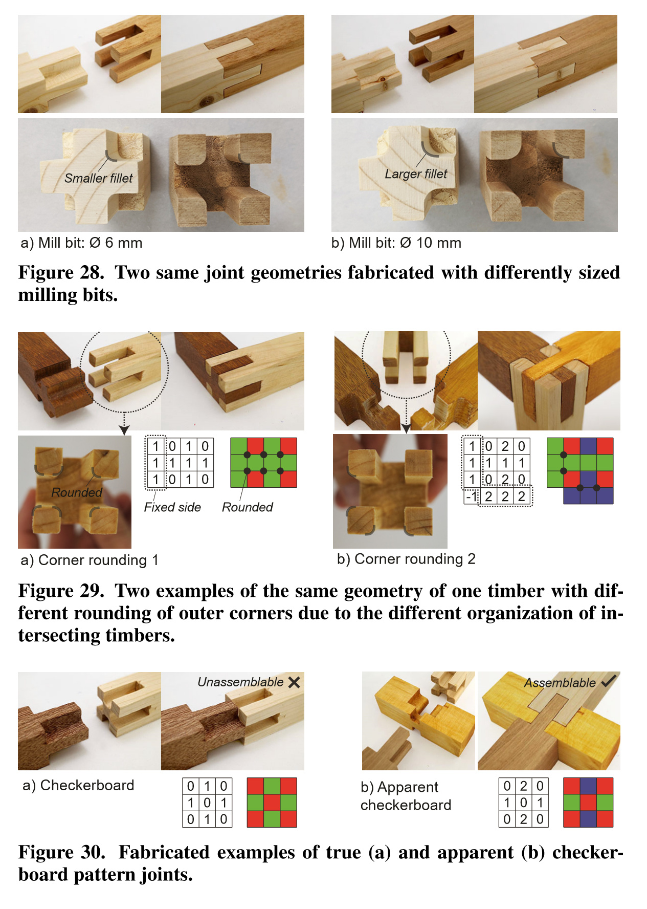
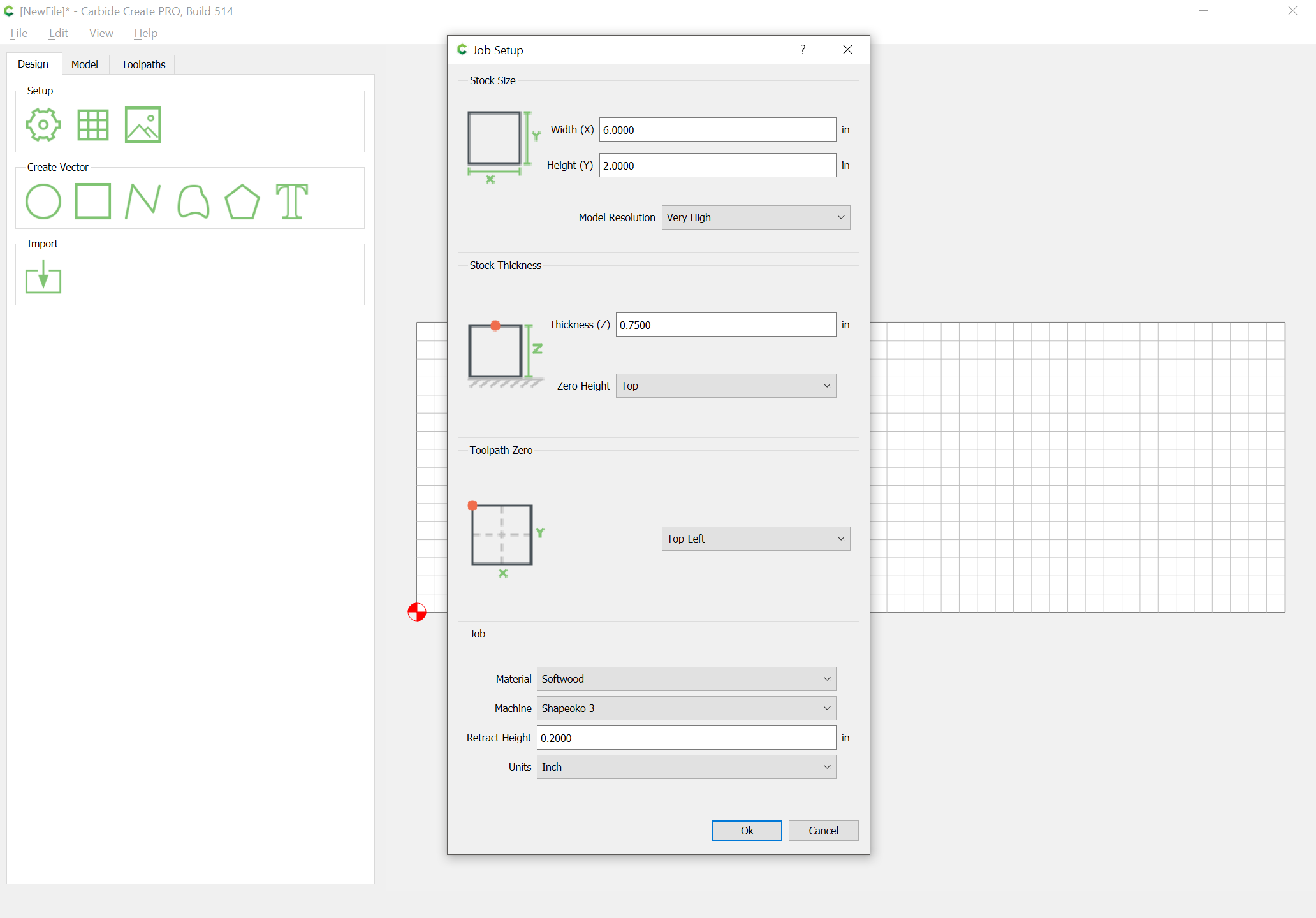
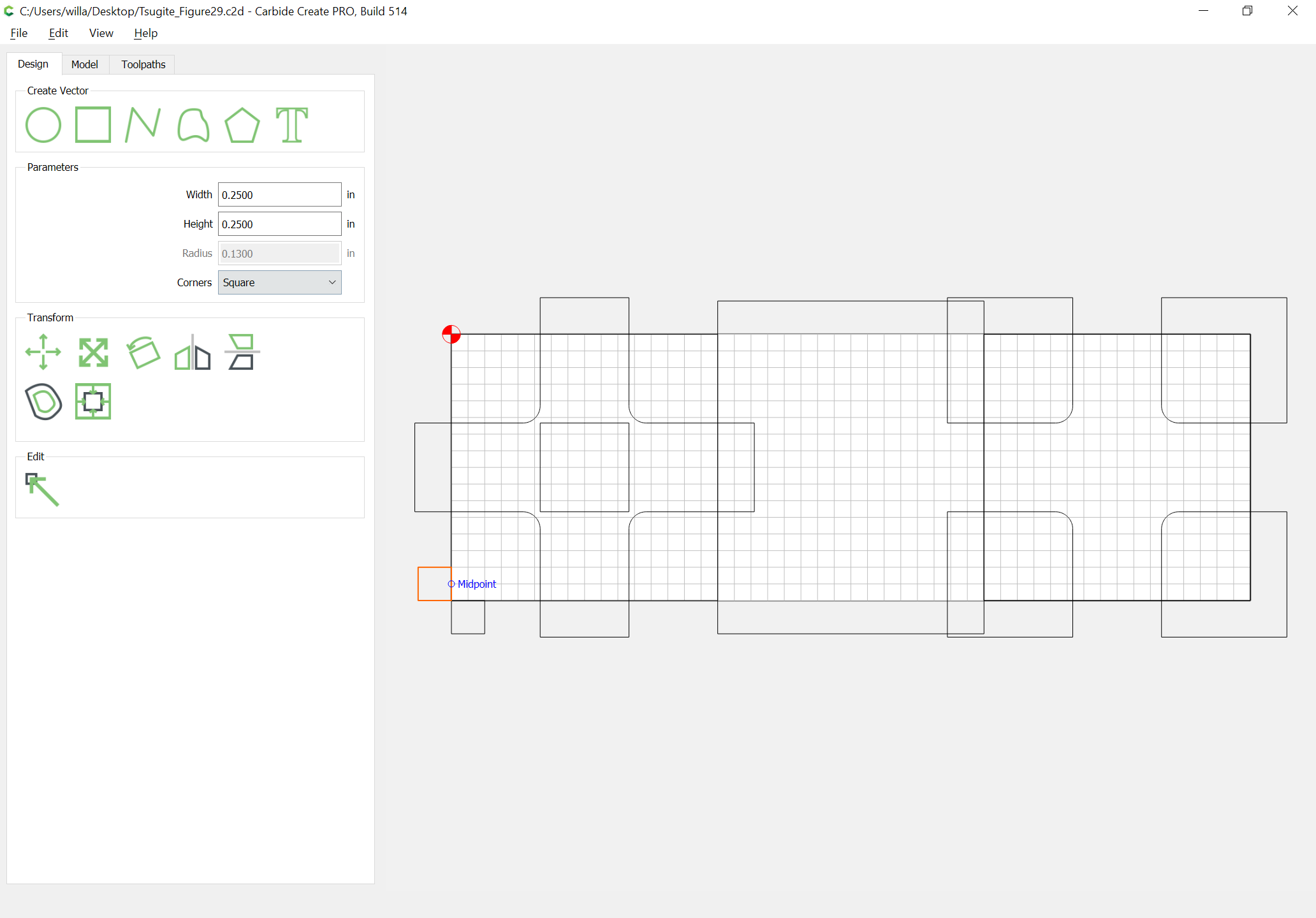
The first consideration is how the stock will be secured — the upper limit is the extent of the overhang of the cutting area — a stock mount with HDZ will probably have the furthest reach (or one can fabricate a baseplate with hole and integrated workholding). A quick check of my machines seems to indicate ~80mm as the upper limit, and ~60mm as a lower. This should allow up to a 2" x 2" board to be used, so we will start with that dimension.
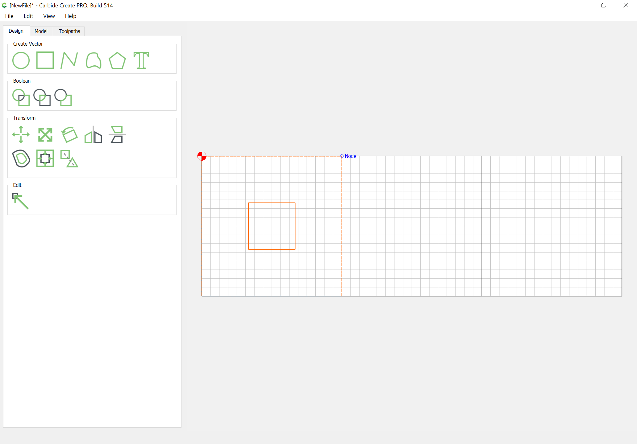
We will start with a 2" x 6" working area with the origin at the upper left (registered against the front plate of the machine):
The assumption is there will be two boards and a 2" spacer (an offcut from them):
You will need an endmill which can make a 2" cut w/o rubbing — sourcing that is left as an exercise for the reader — note that the material will need to mounted so that it projects at least 2" above the endplate.
Divide by thirds:
(Usually I would do this sort of thing in an application which supports PostScript Points and Picas so that rounding such as is seen above would not occur)
and center:
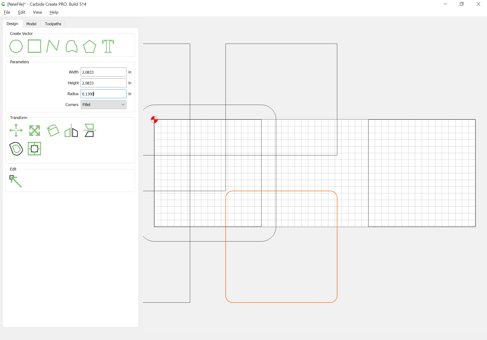
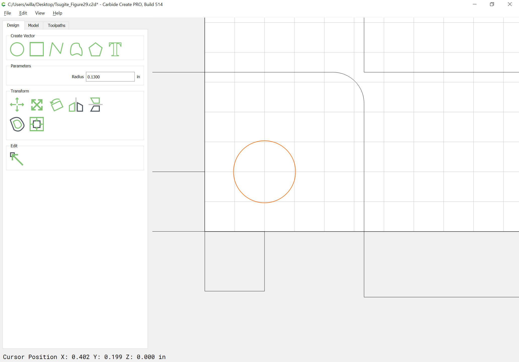
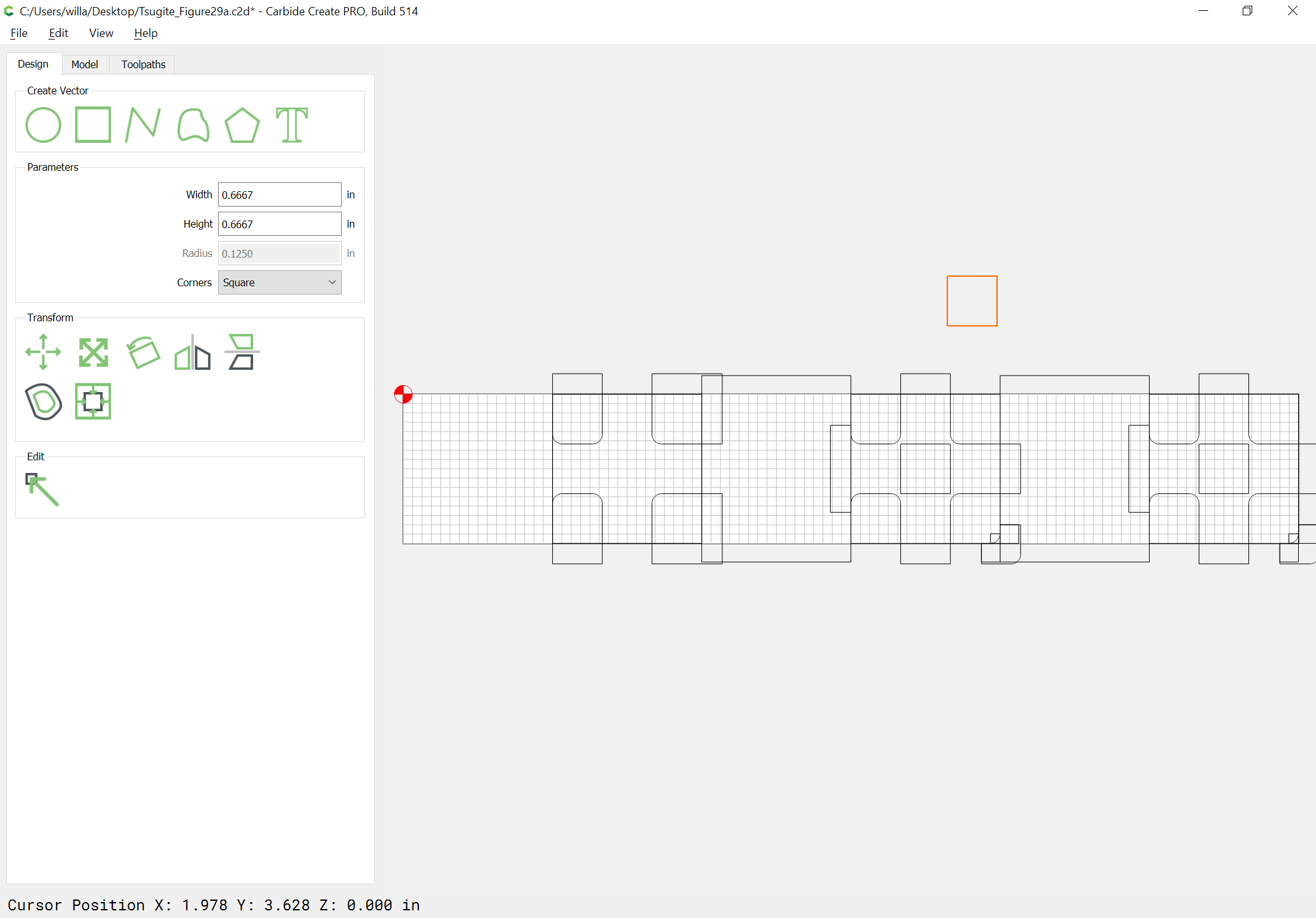
Then offset the square which defines the stock to cut by the endmill diameter plus 10% (we’ll assume an 0.25" endmill):
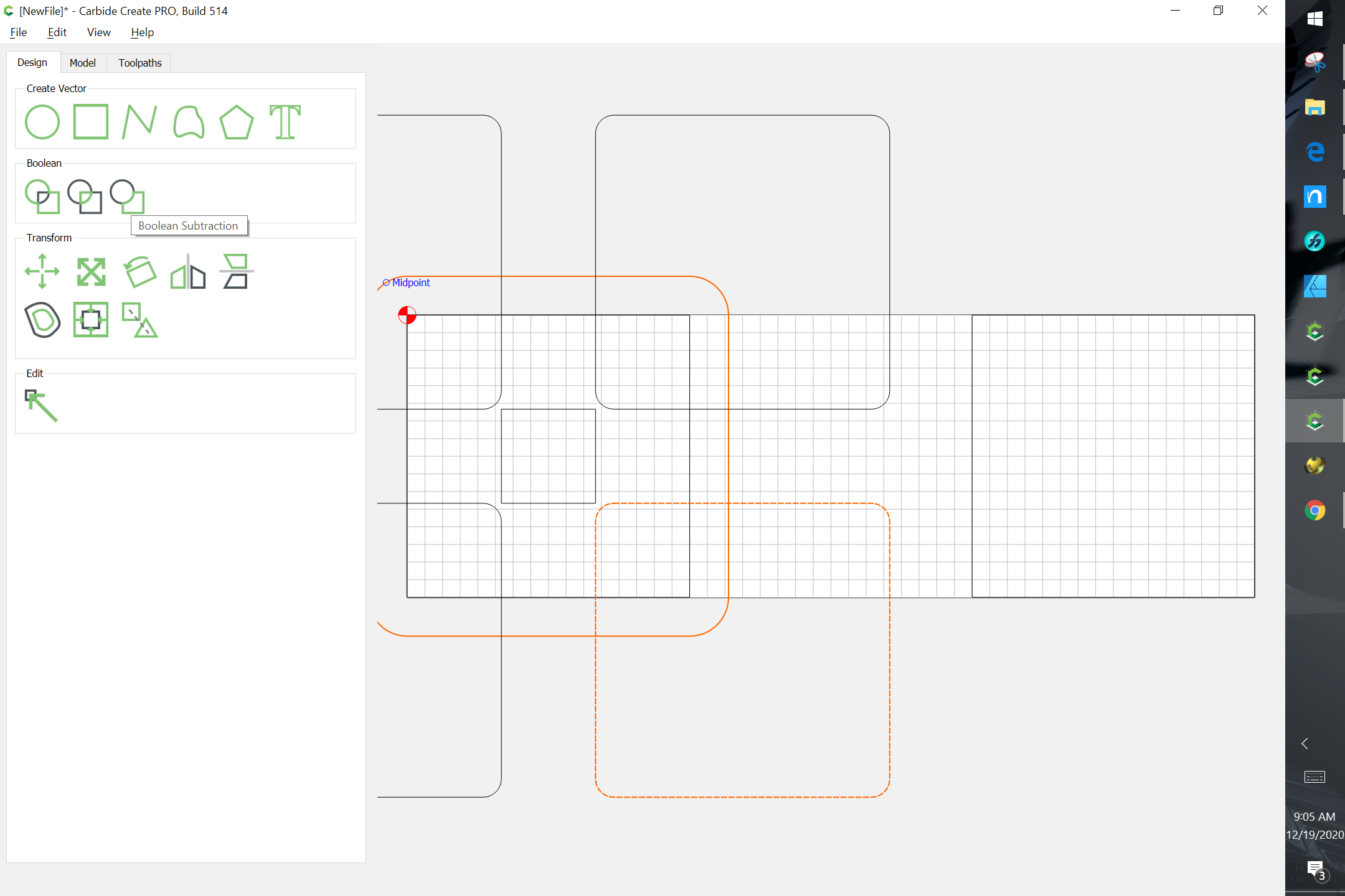
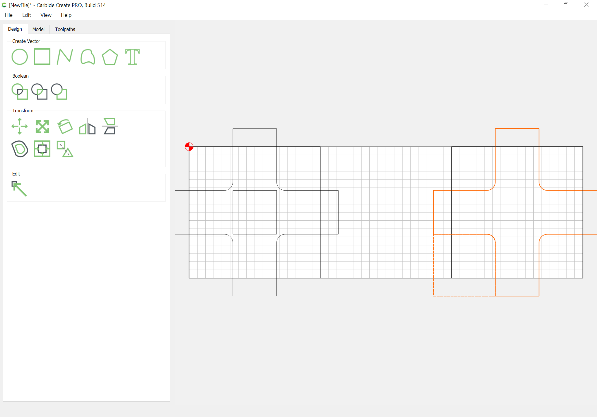
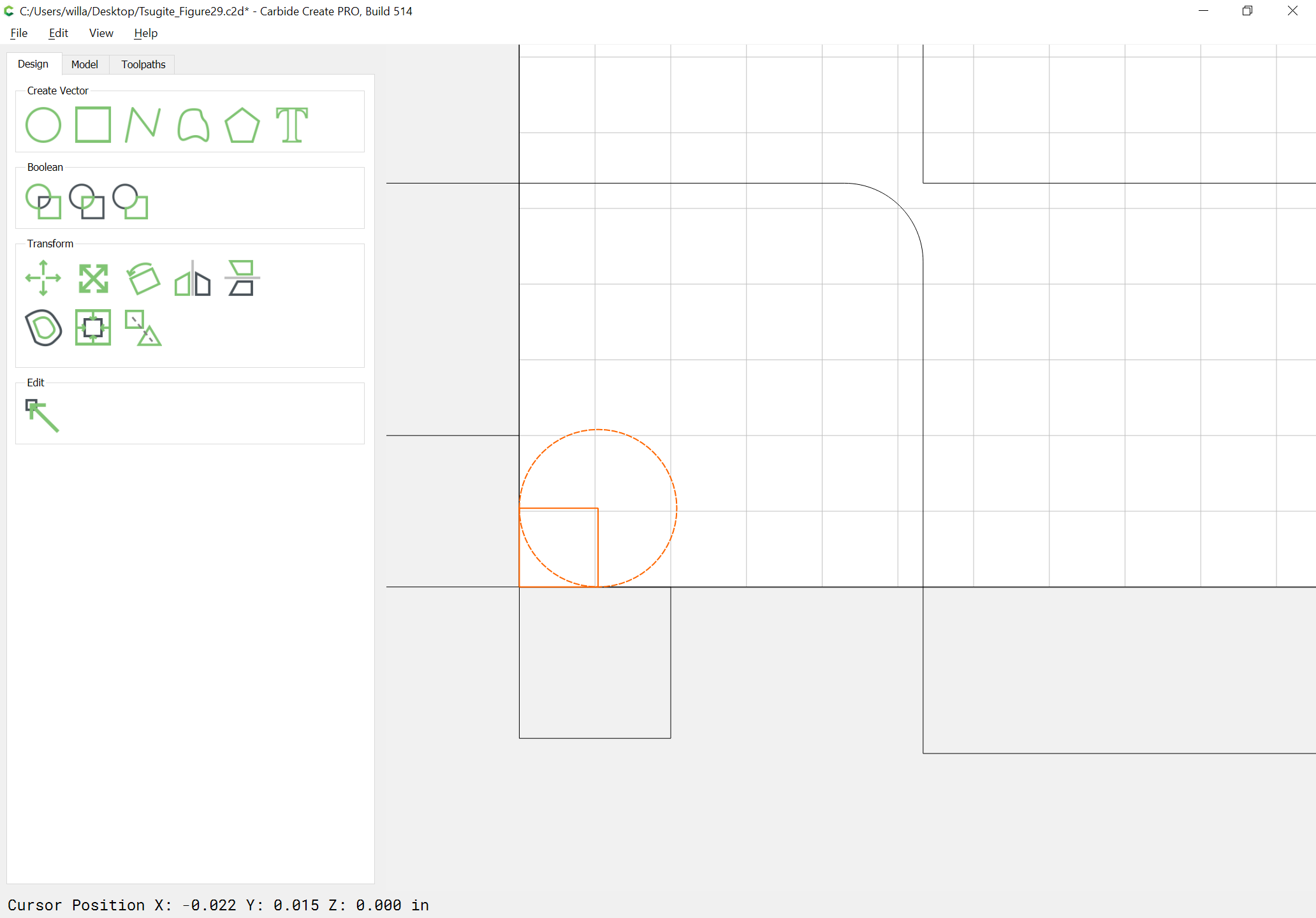
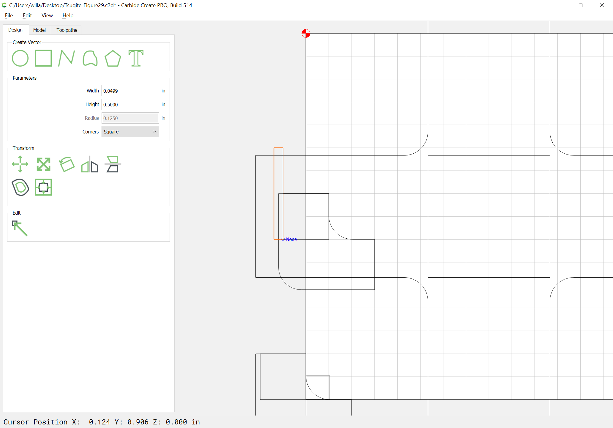
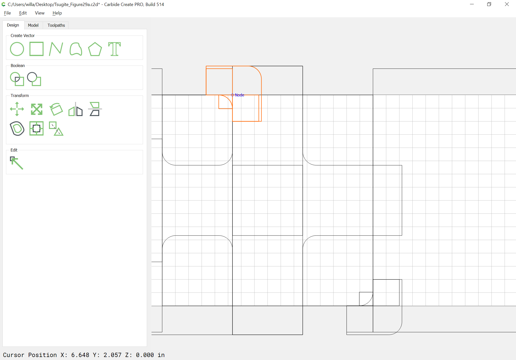
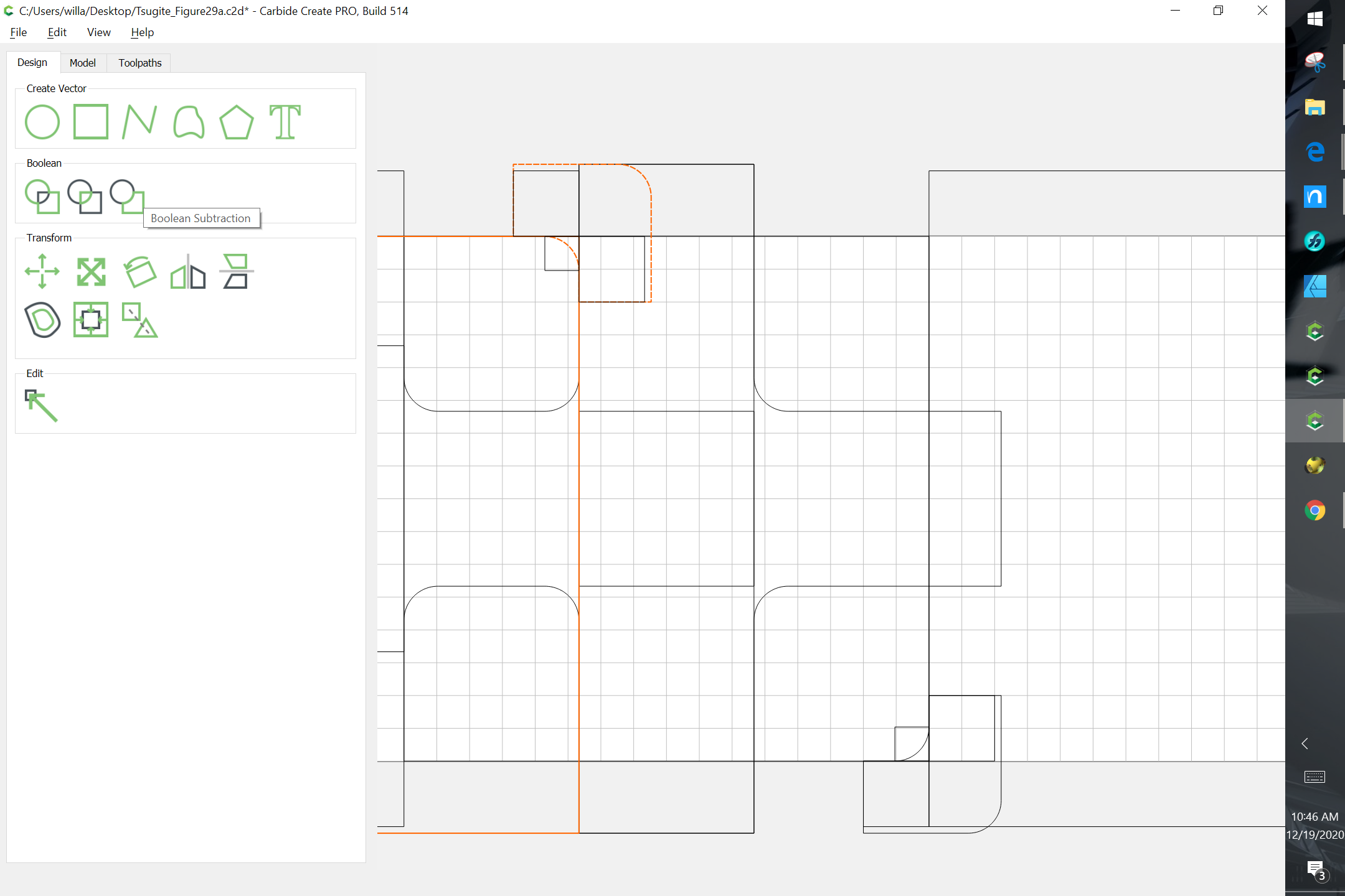
Draw in squares which are larger than the corners and go past the outer geometry:
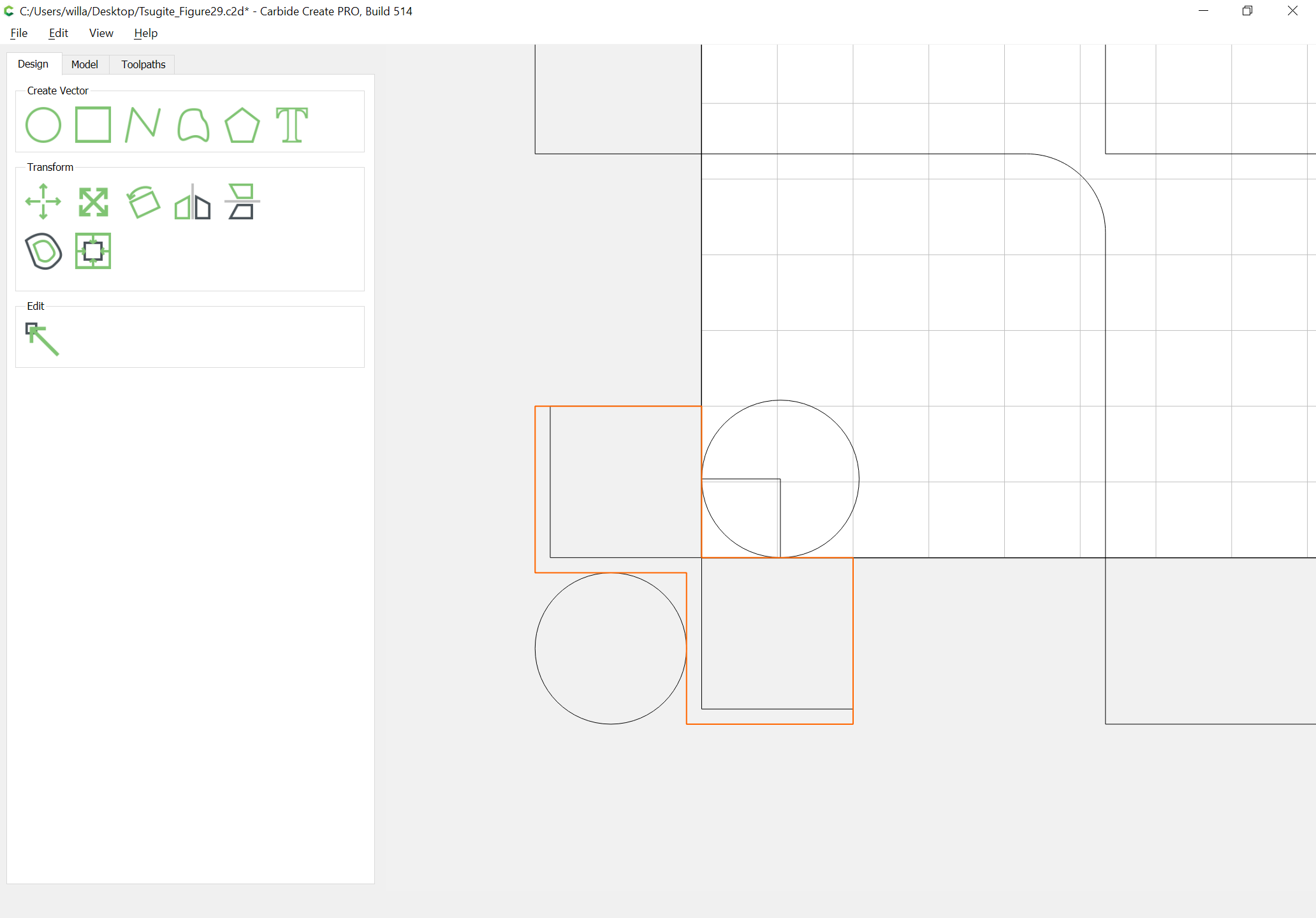
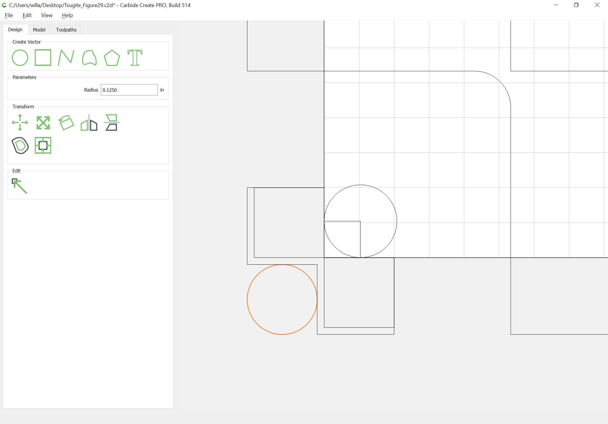
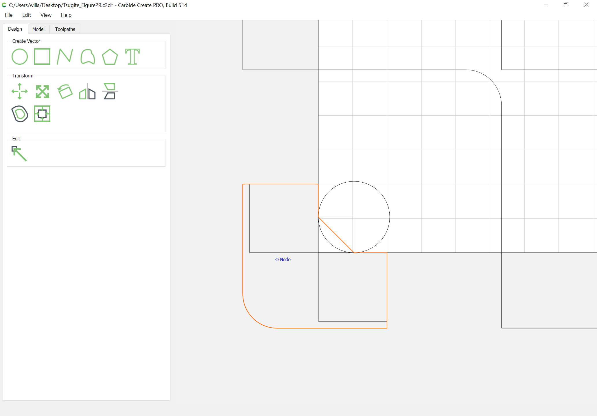
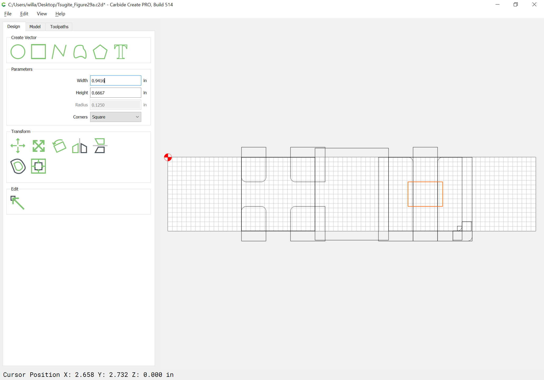
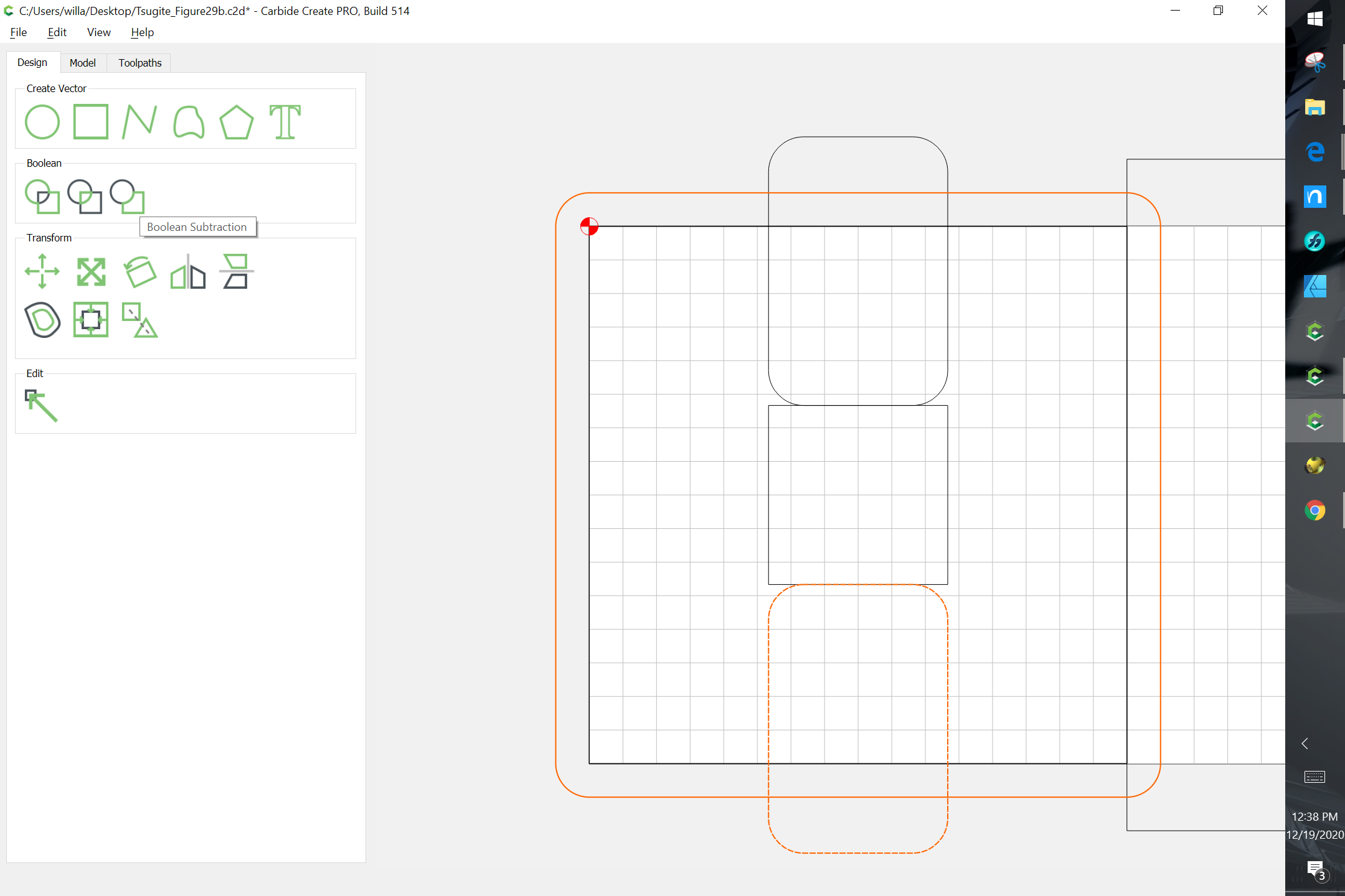
Round them off to be a bit more than the endmill radius:
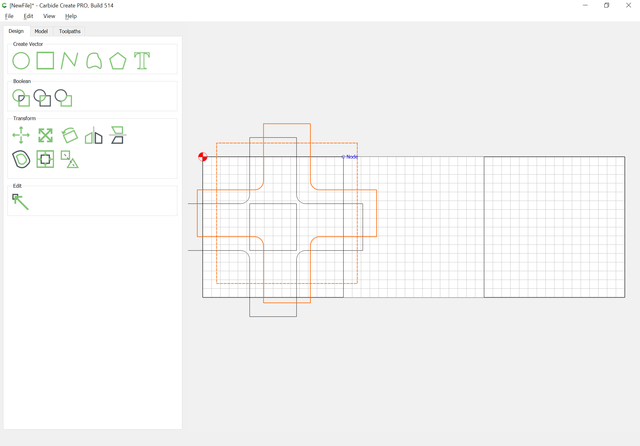
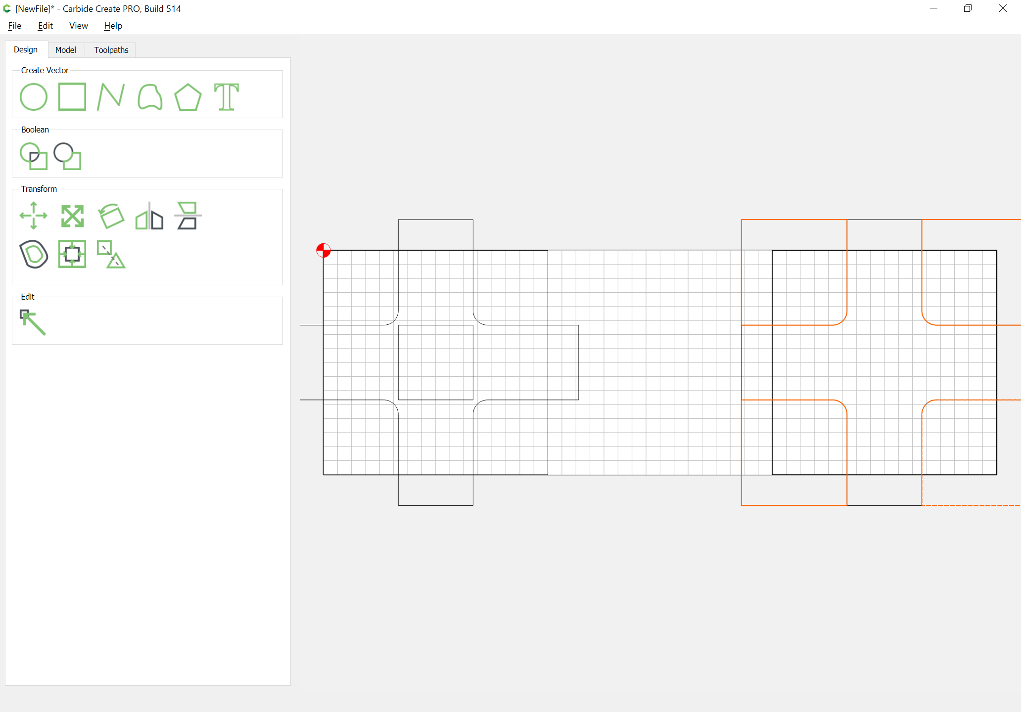
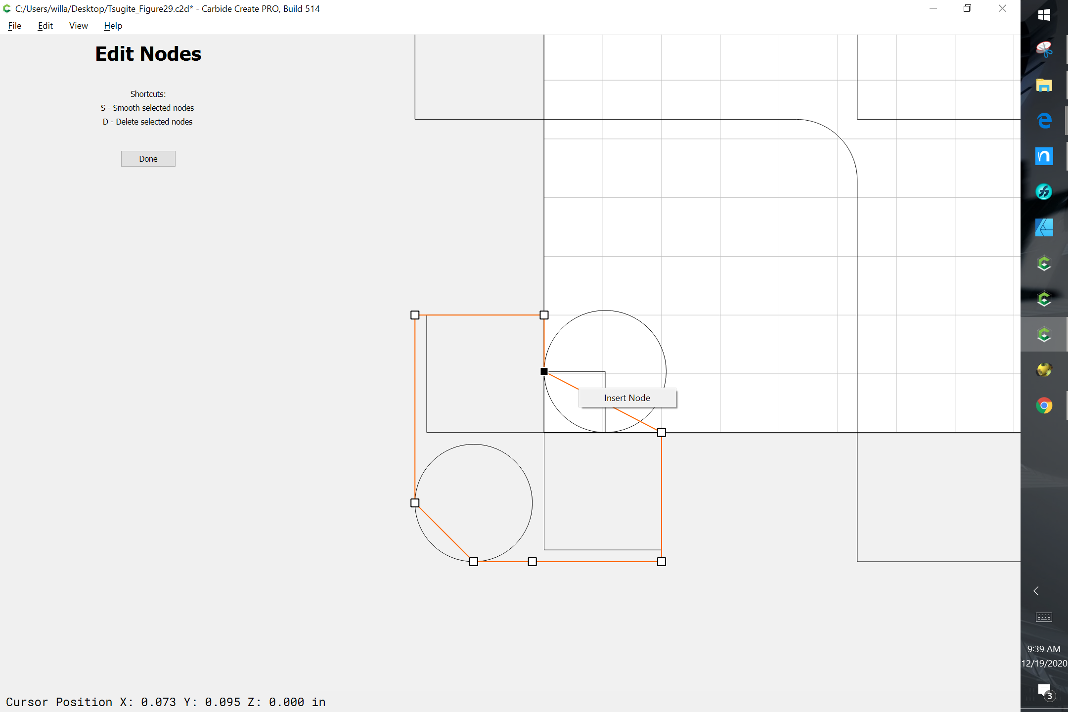
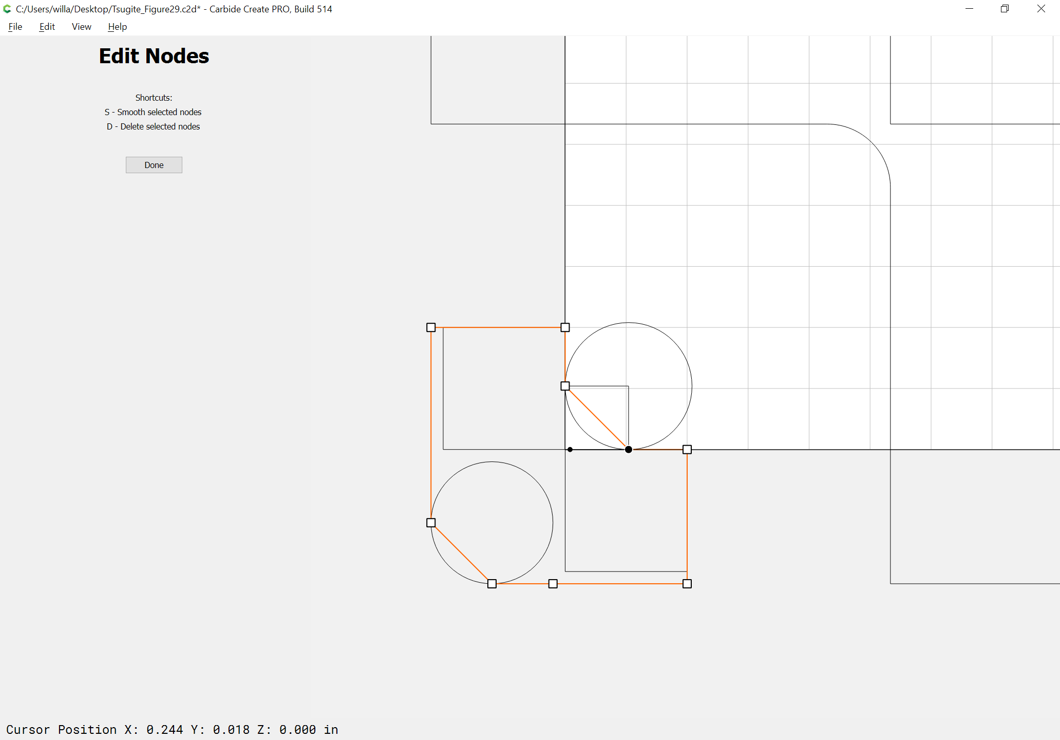
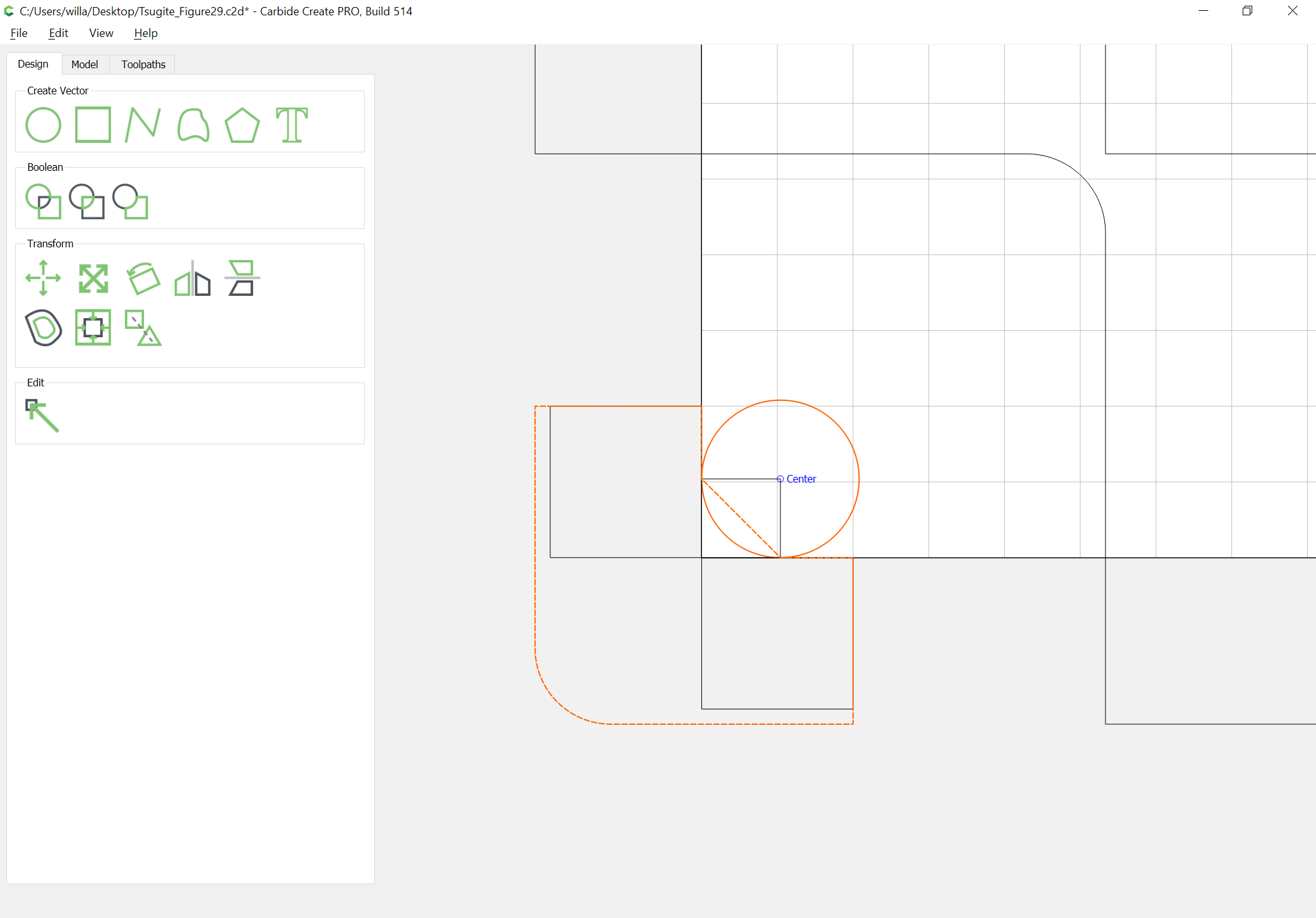
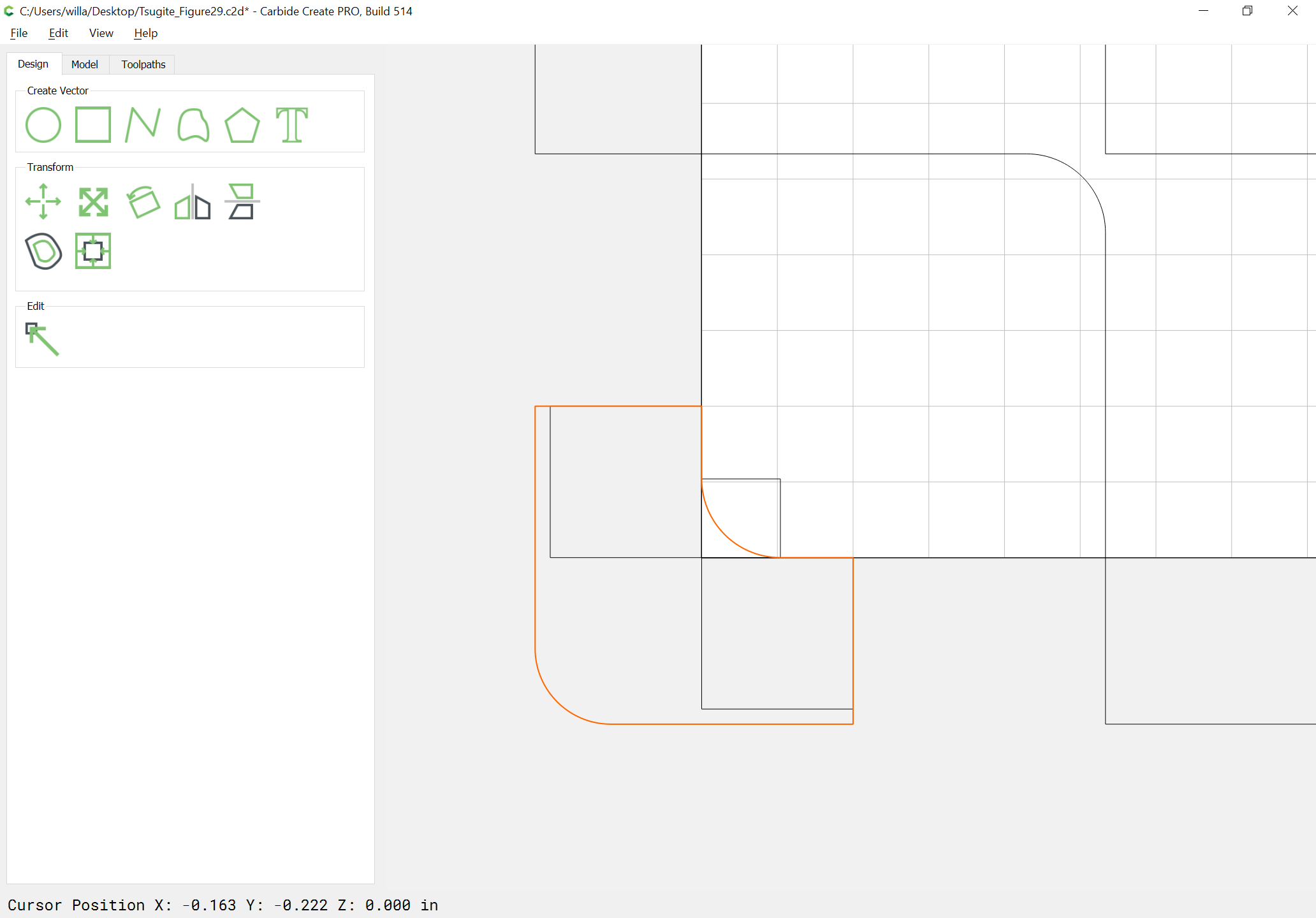
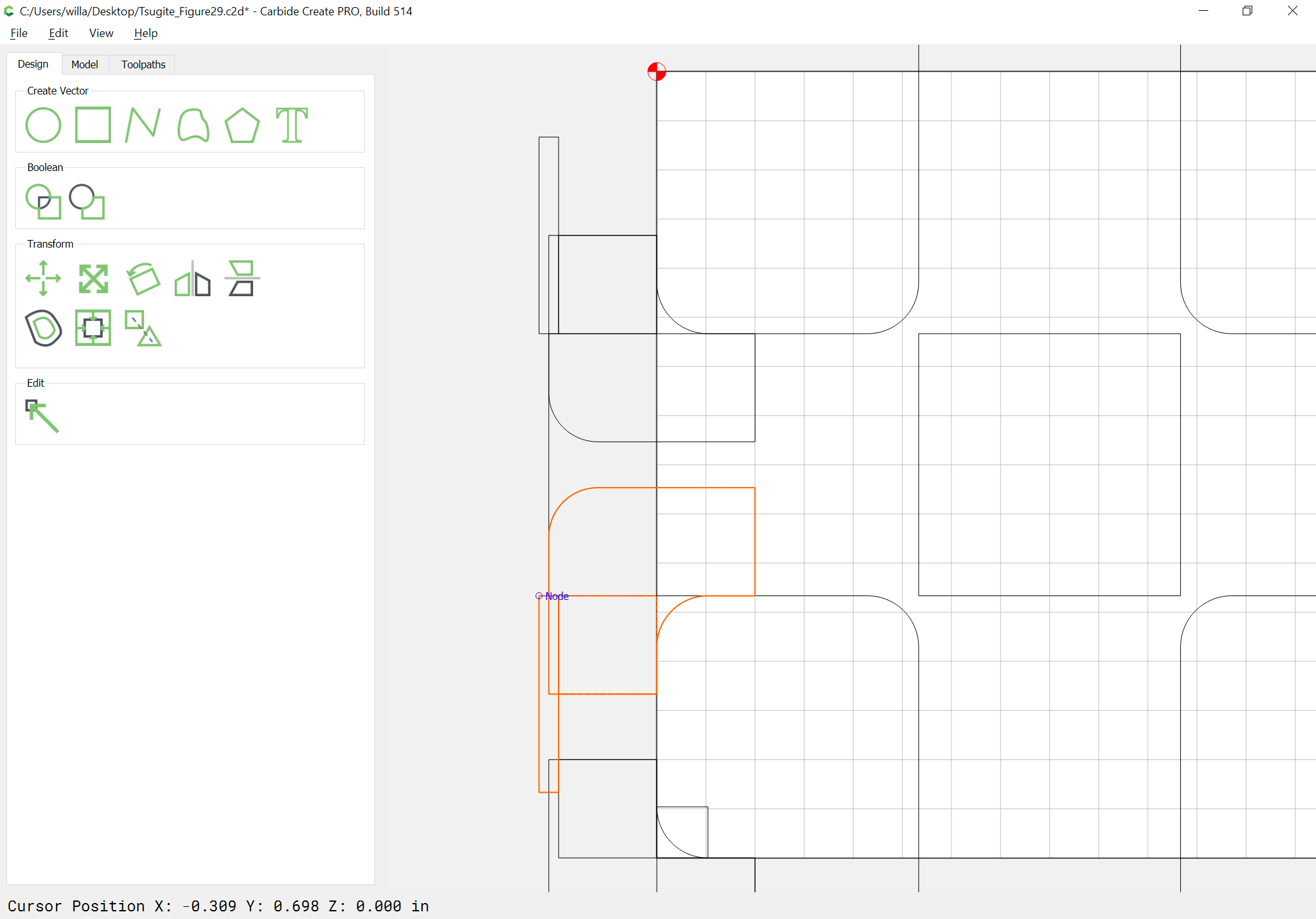
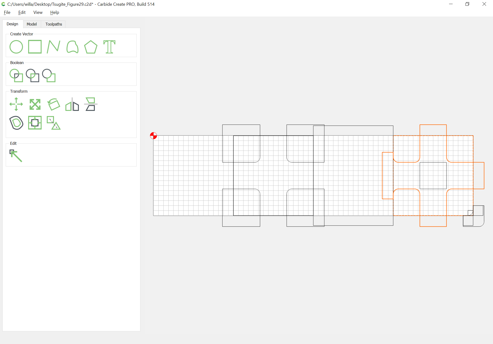
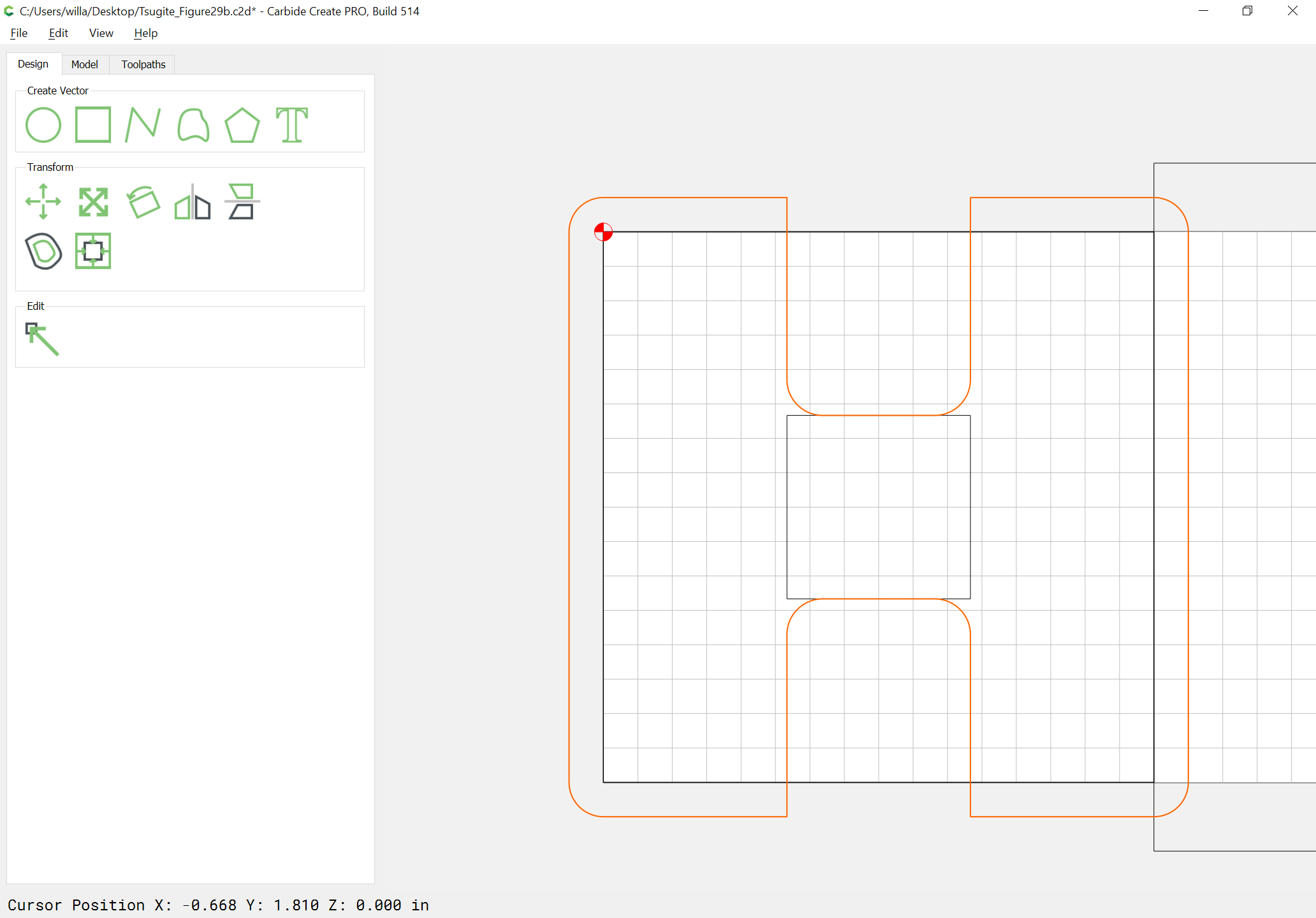
Boolean subtract each from the endmill radius plus offset geometry:
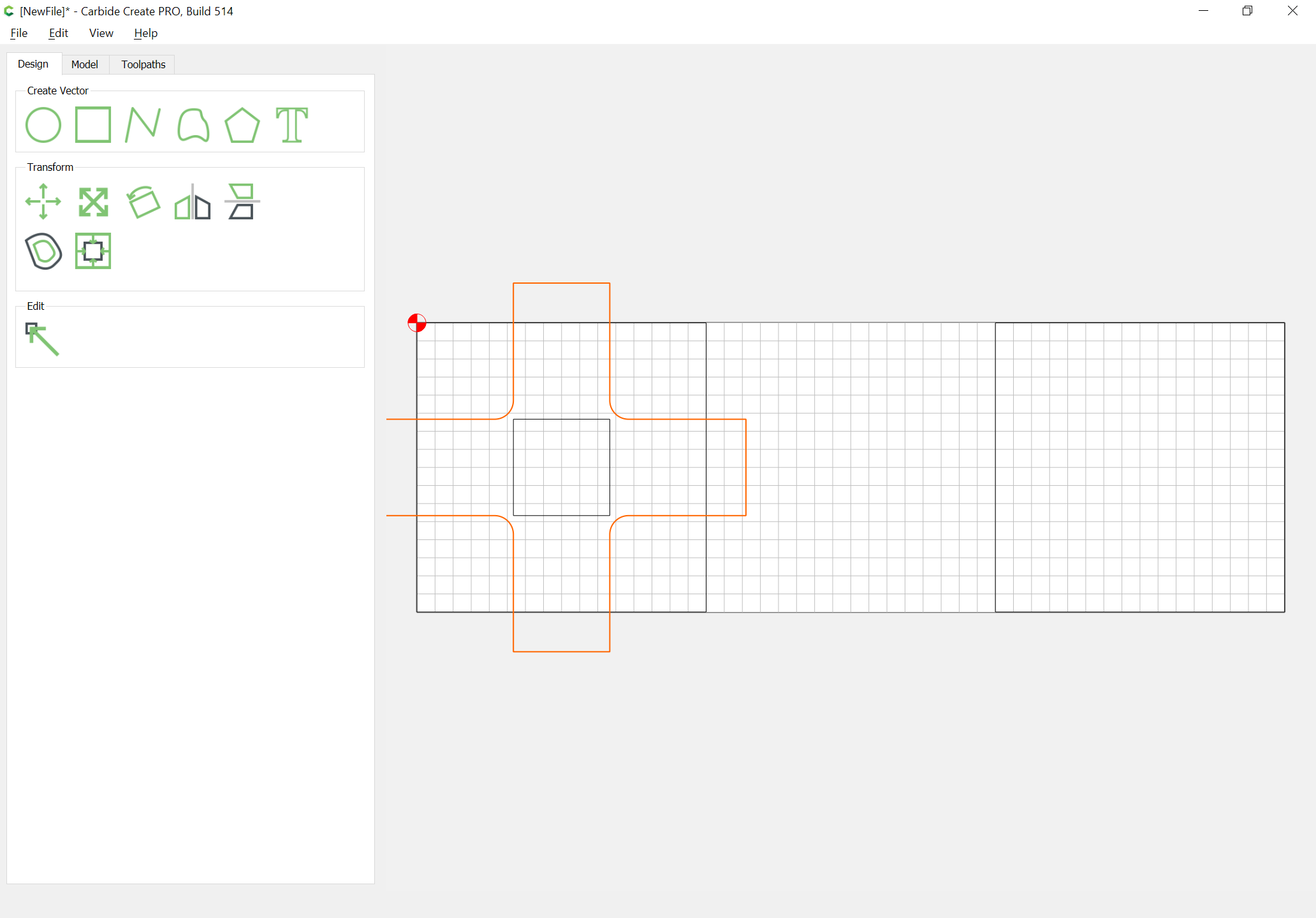
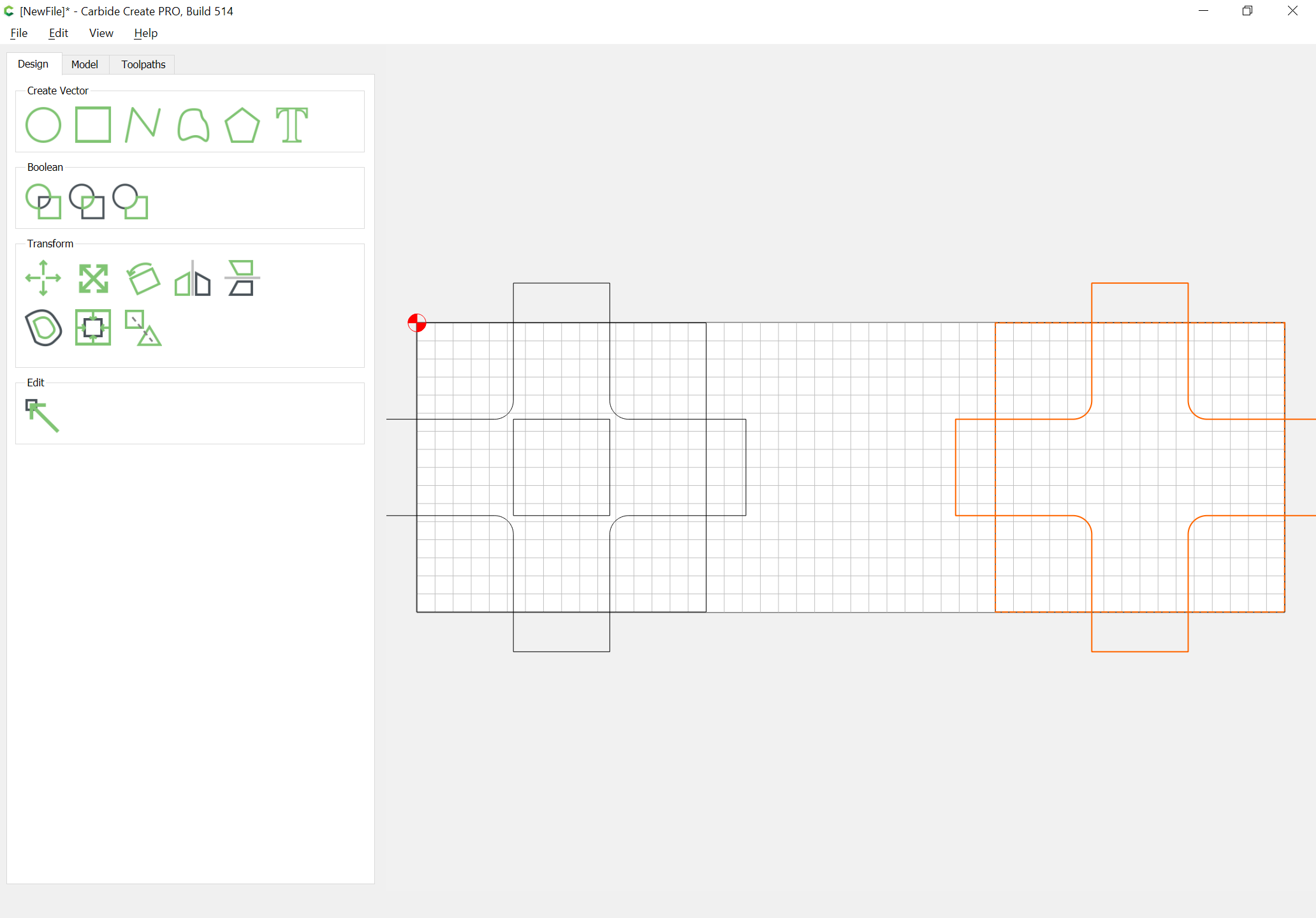
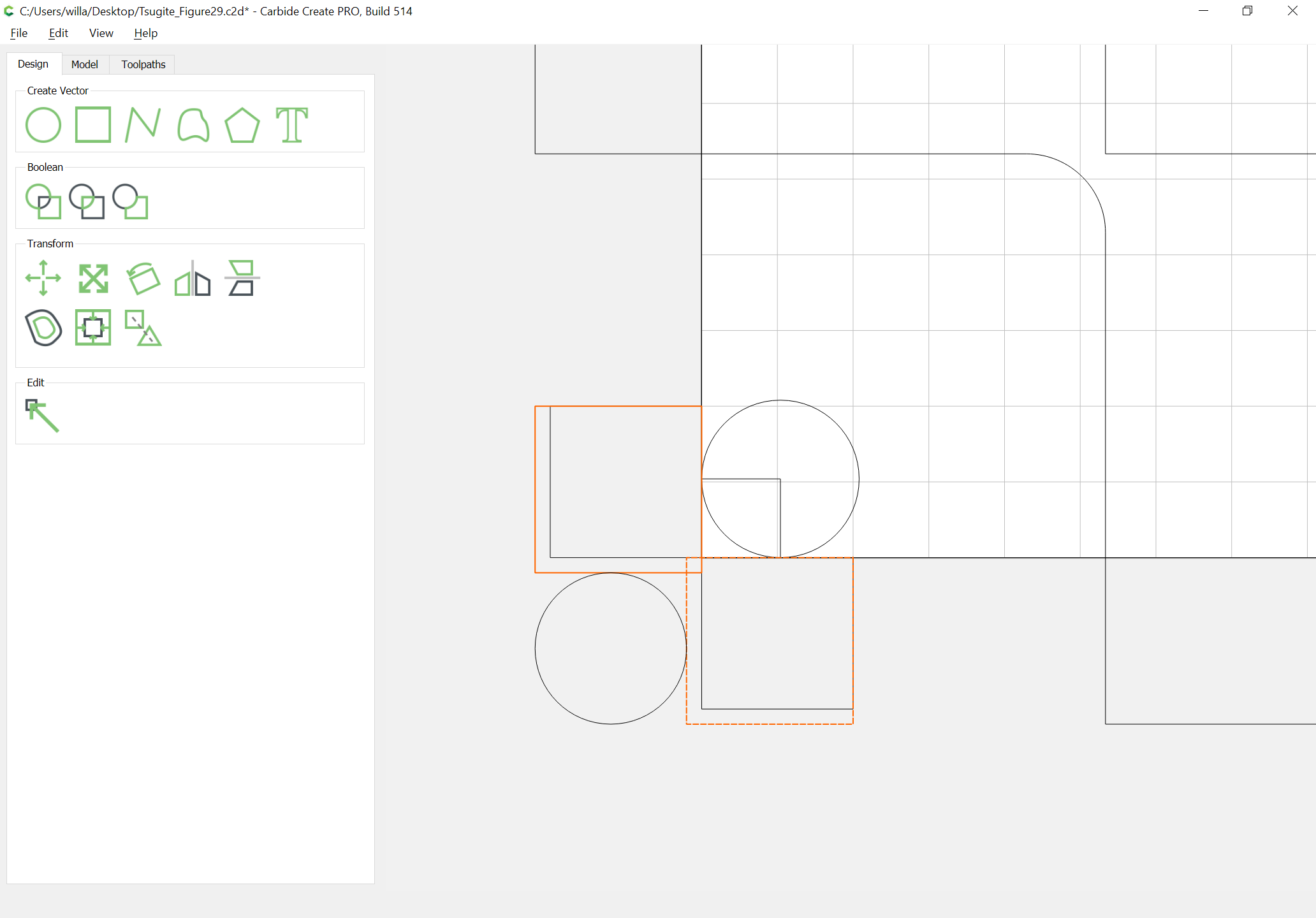
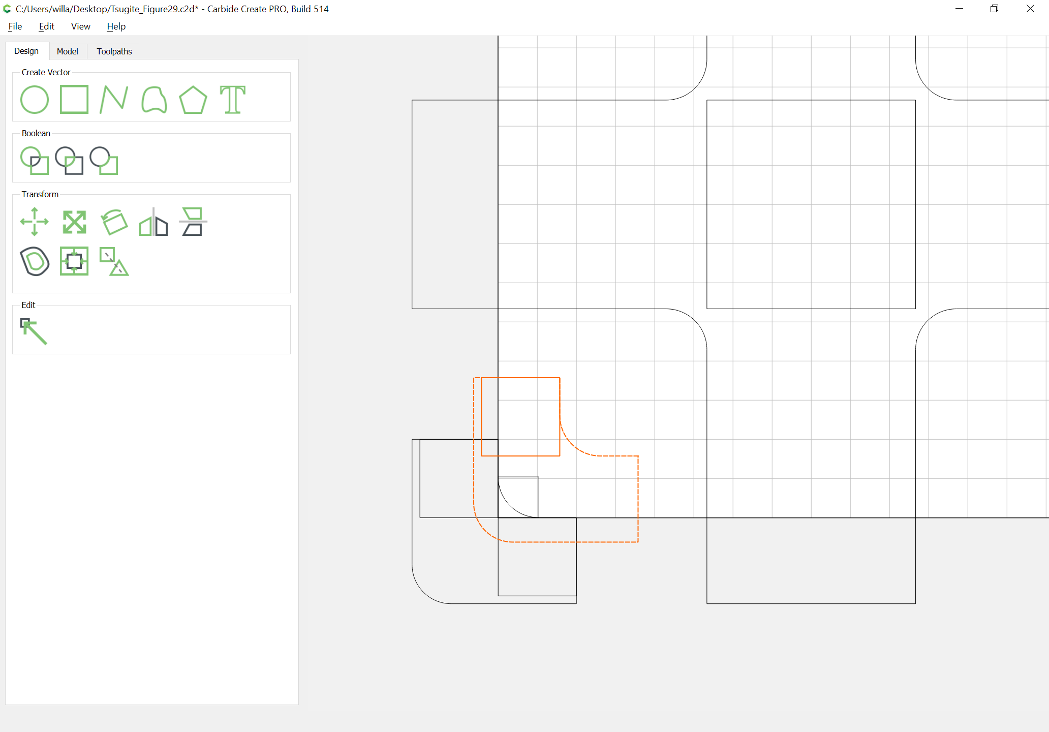
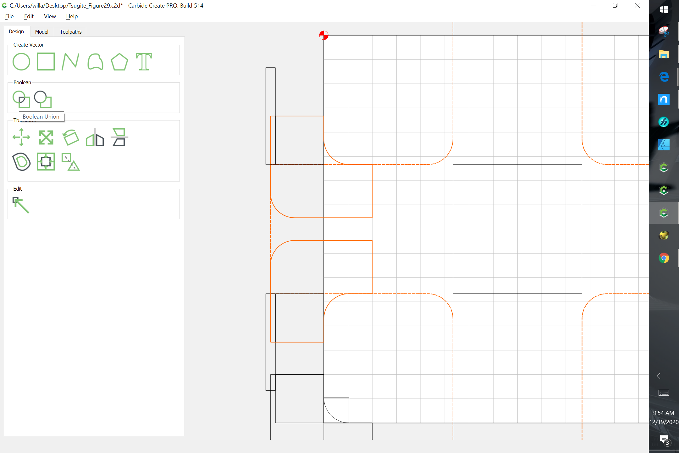
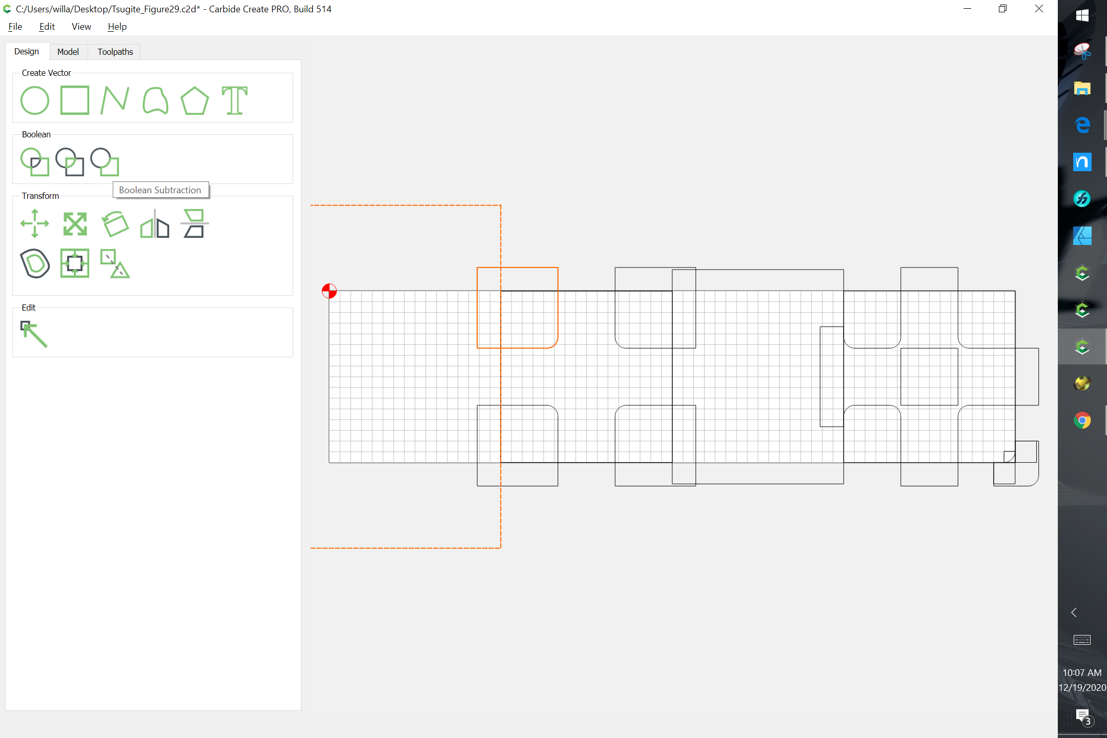
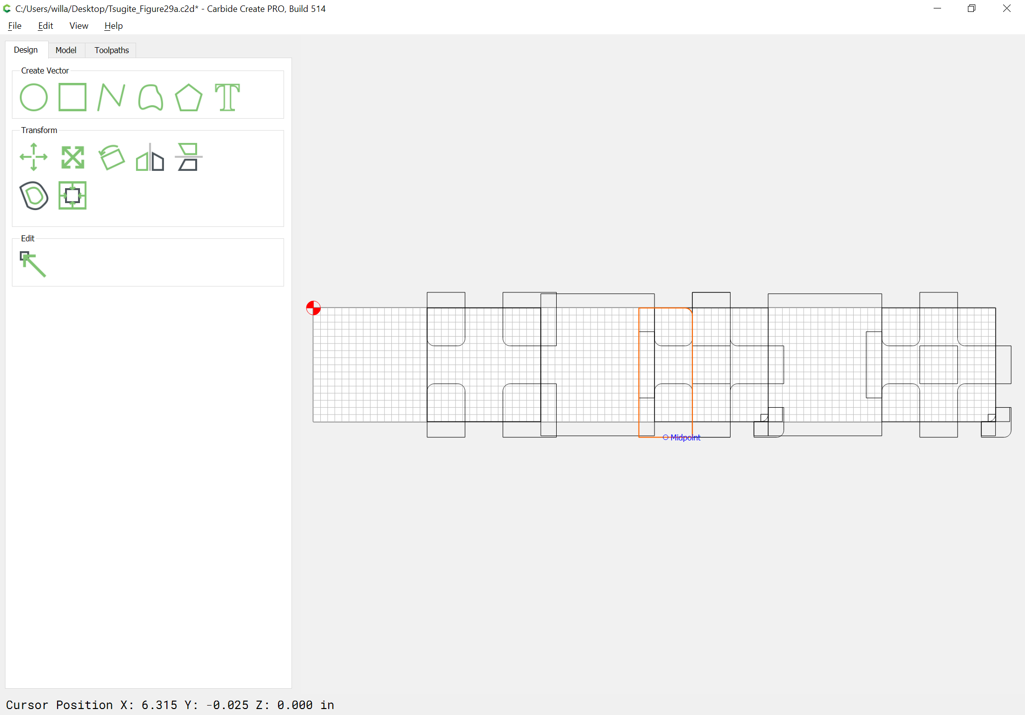
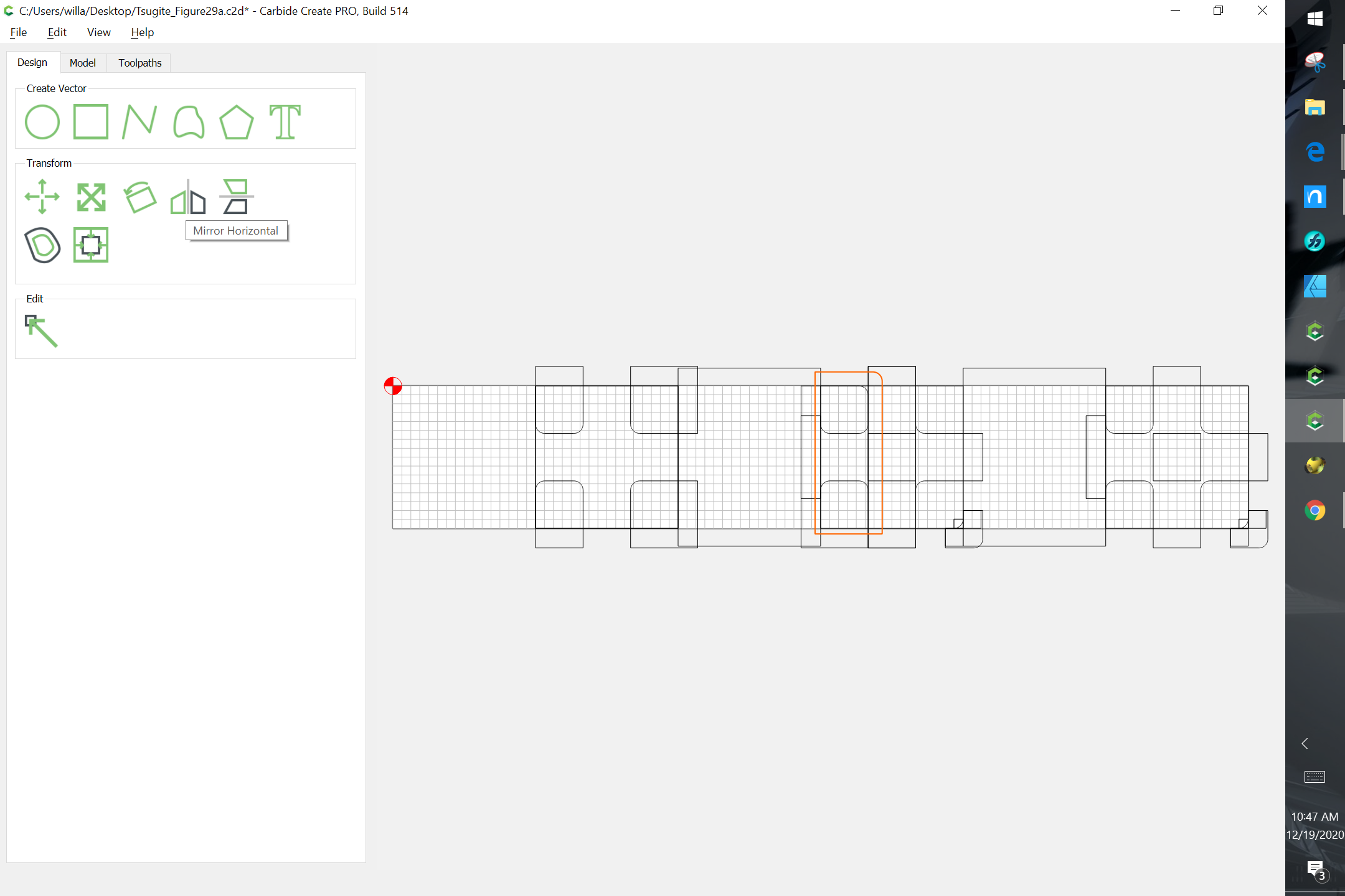
Duplicate the geometry:
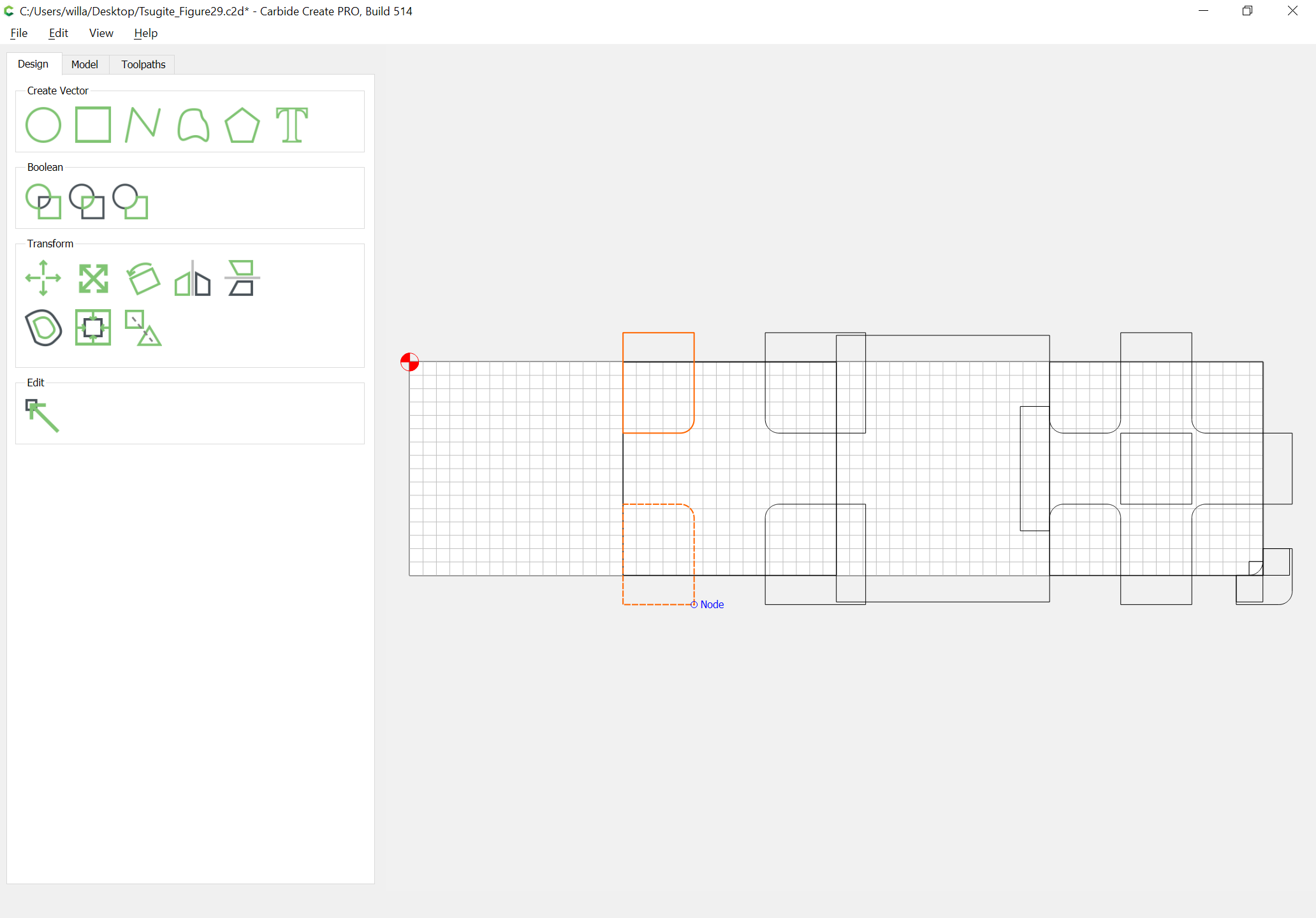
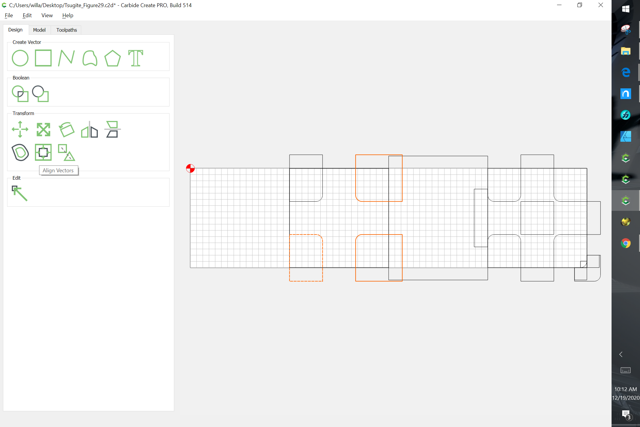
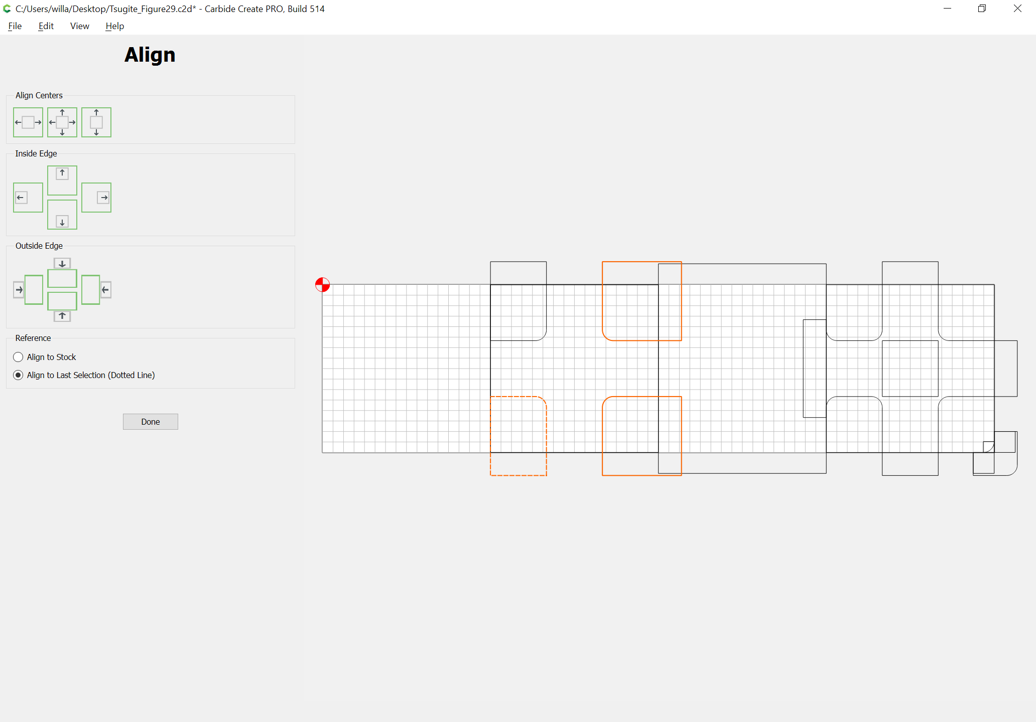
and drag it into alignment:
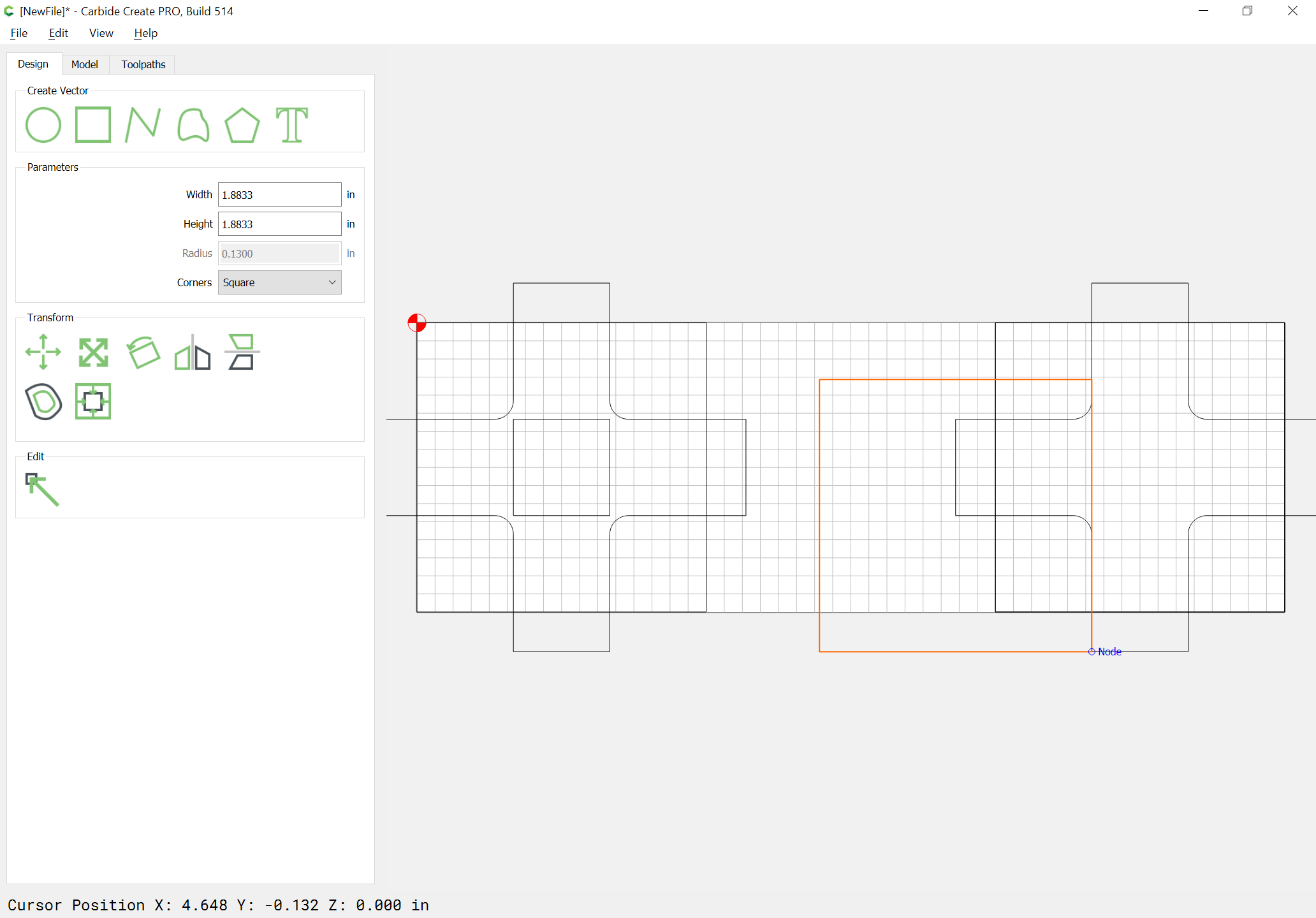
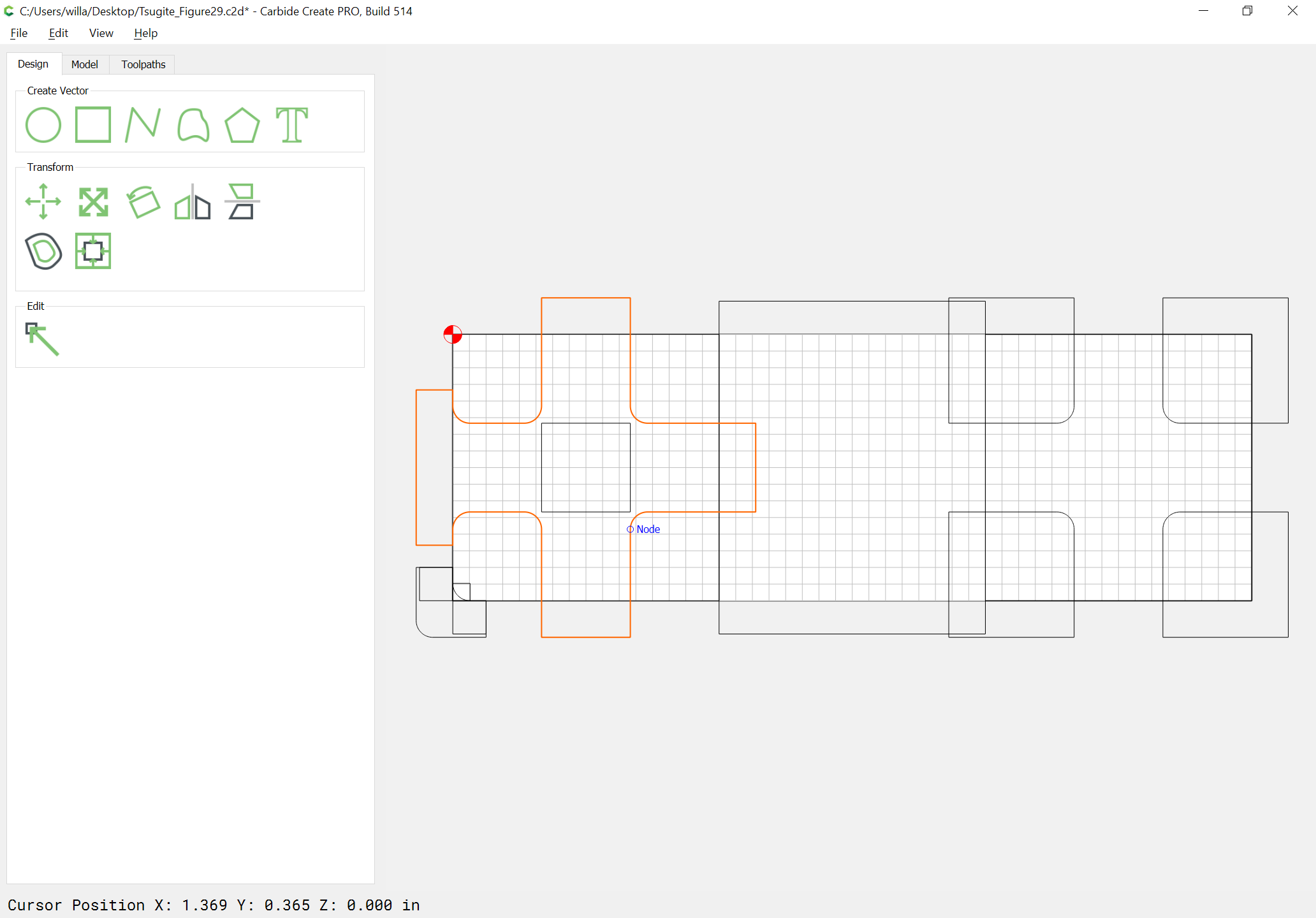
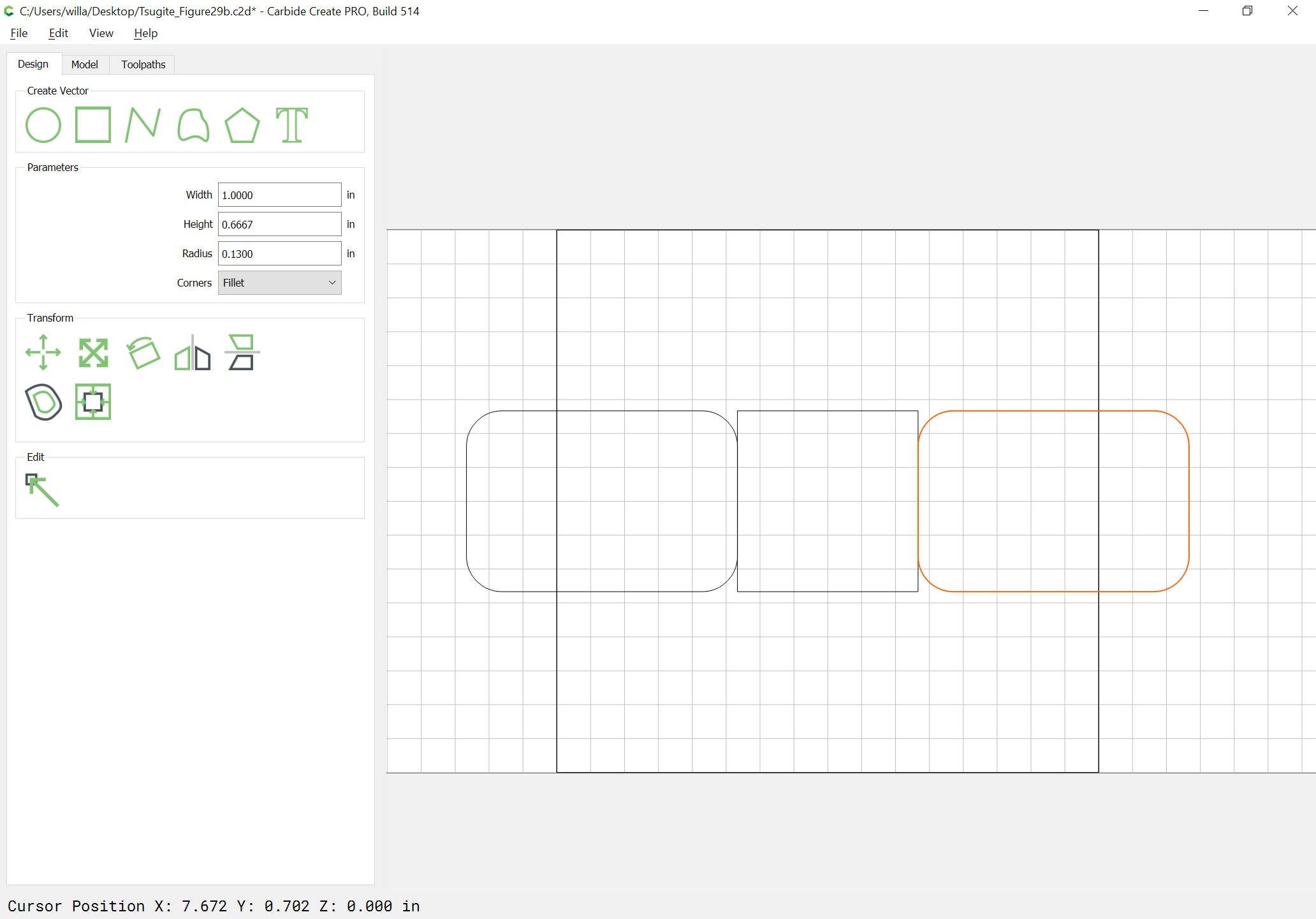
Draw in a square which goes from corner-to-corner and is twice as large as needed:
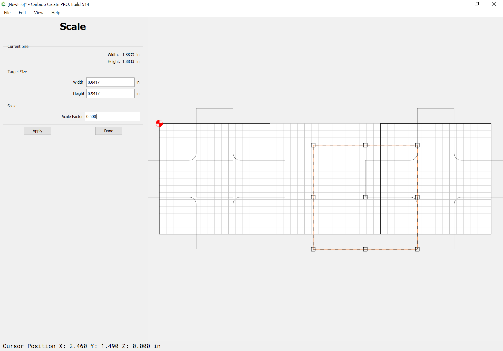
and scale it down 0.5 to the size needed and drag it into alignment:
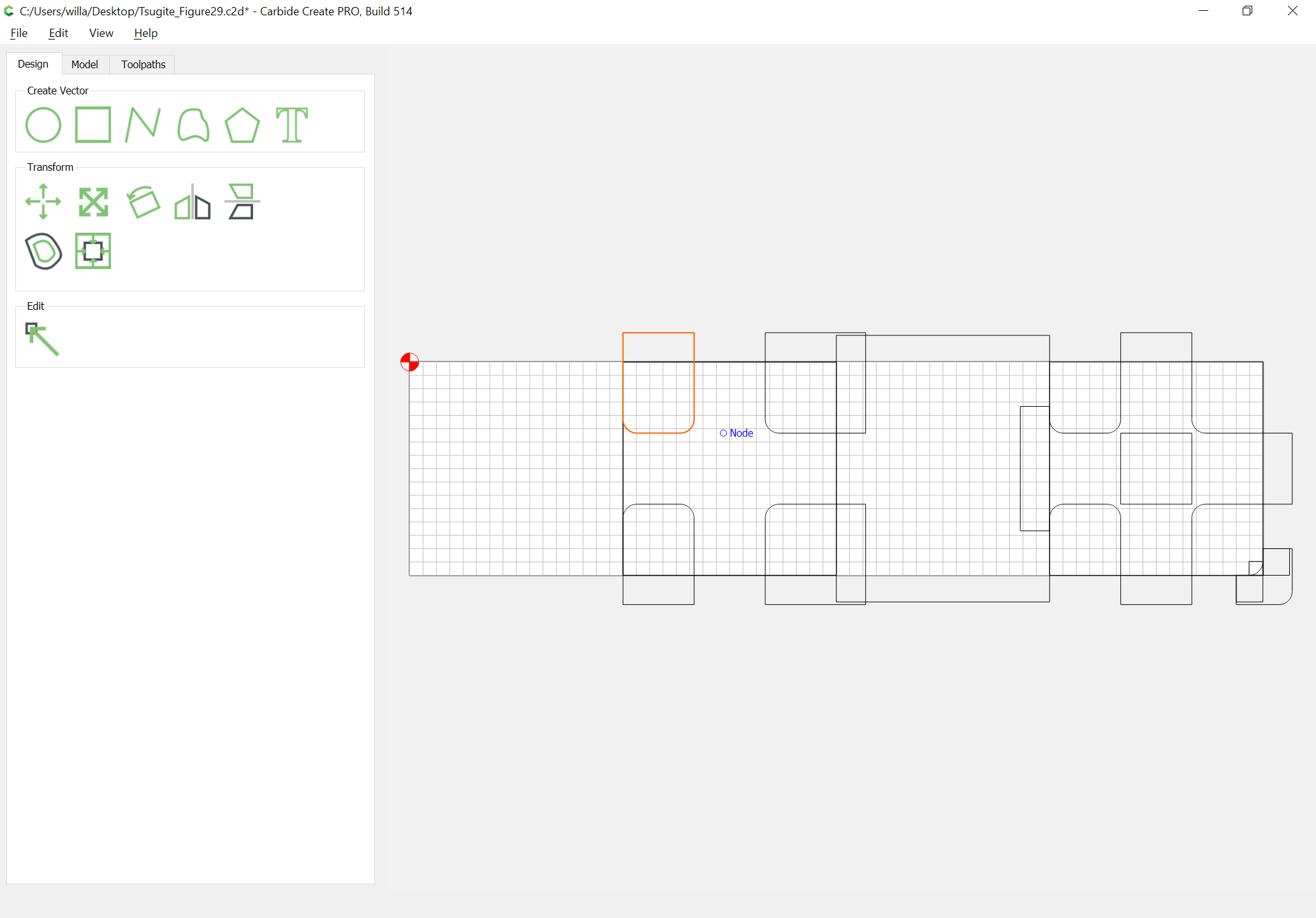
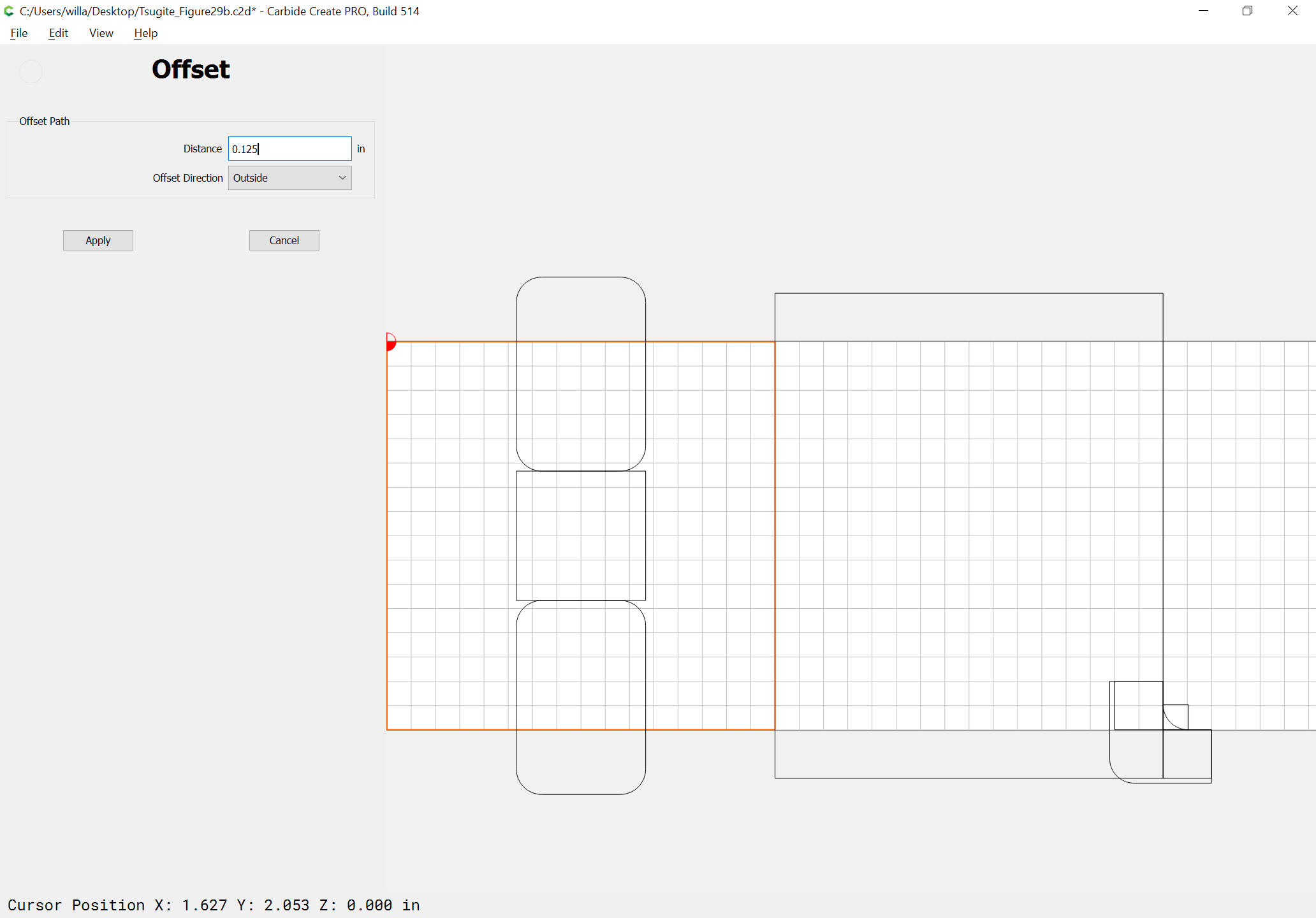
Boolean subtract the geometry which defines the area to be removed from the square:
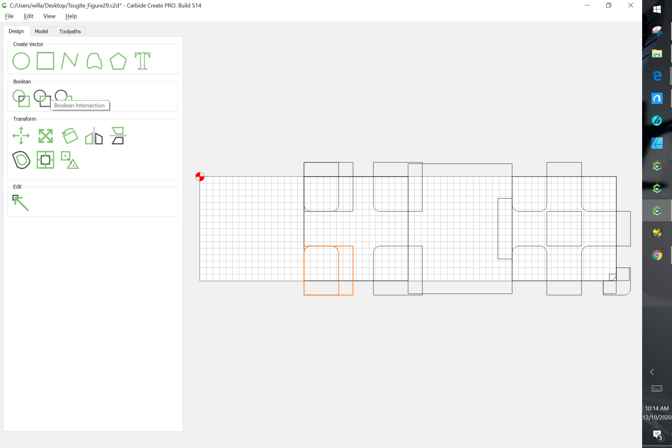
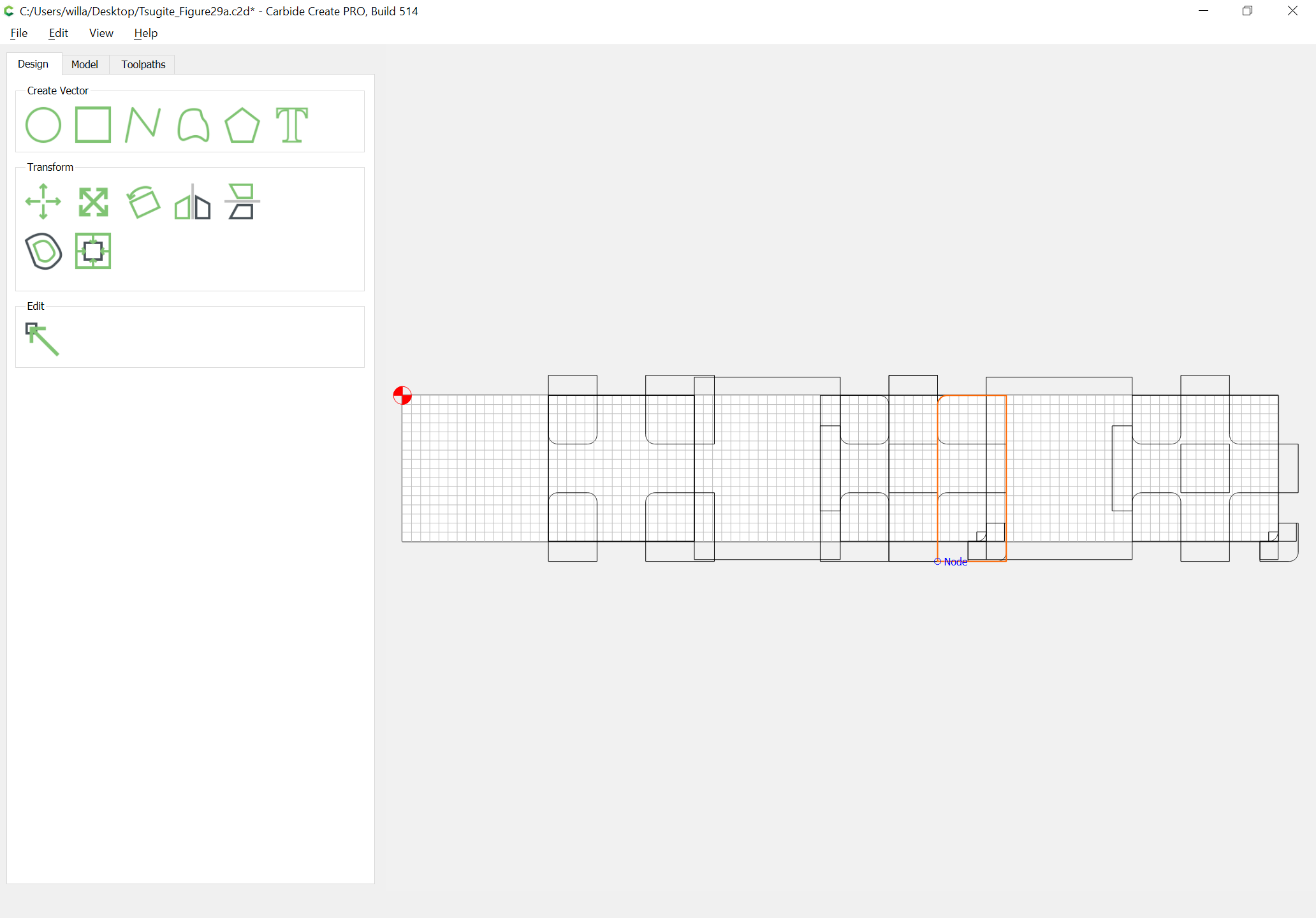
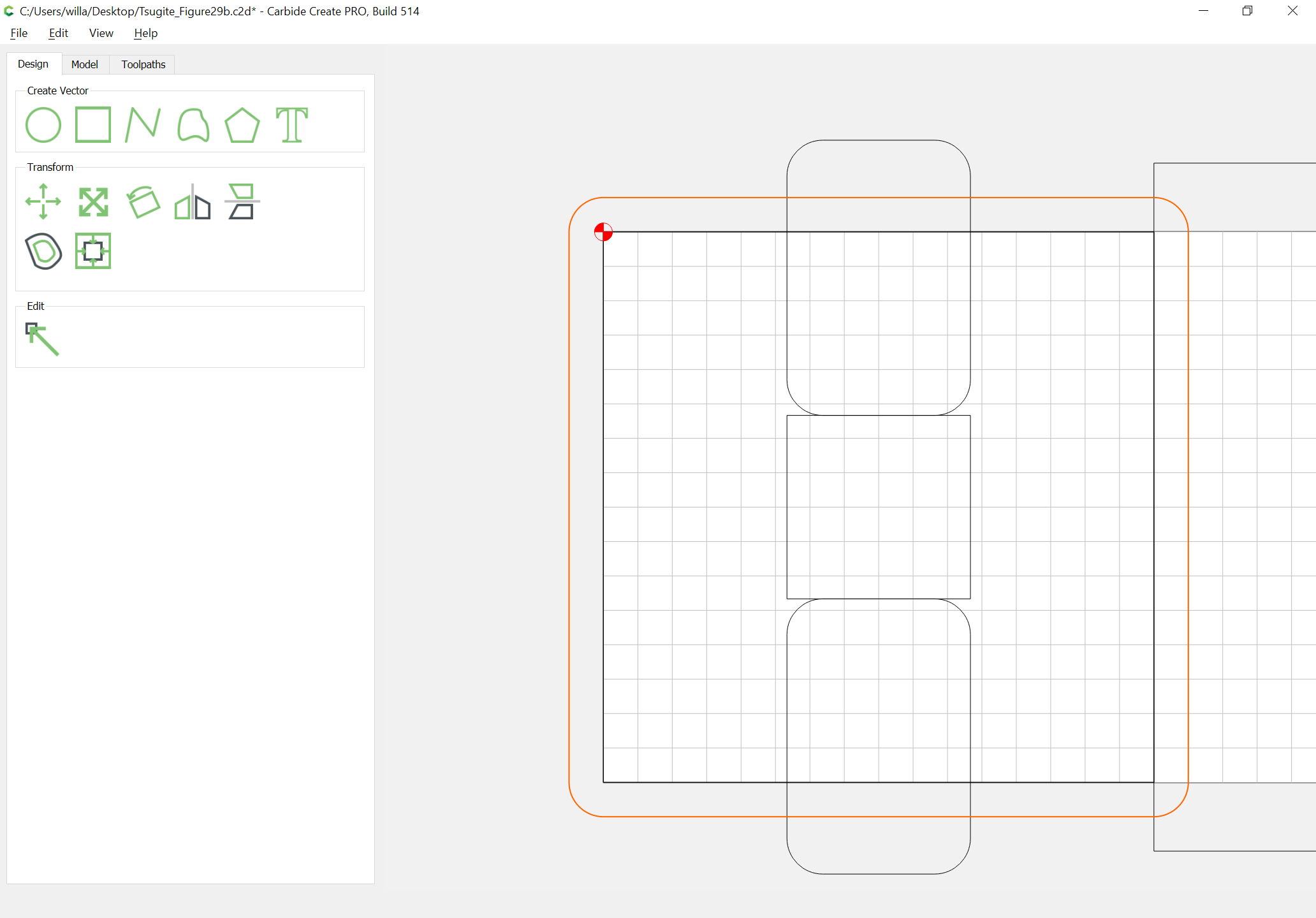
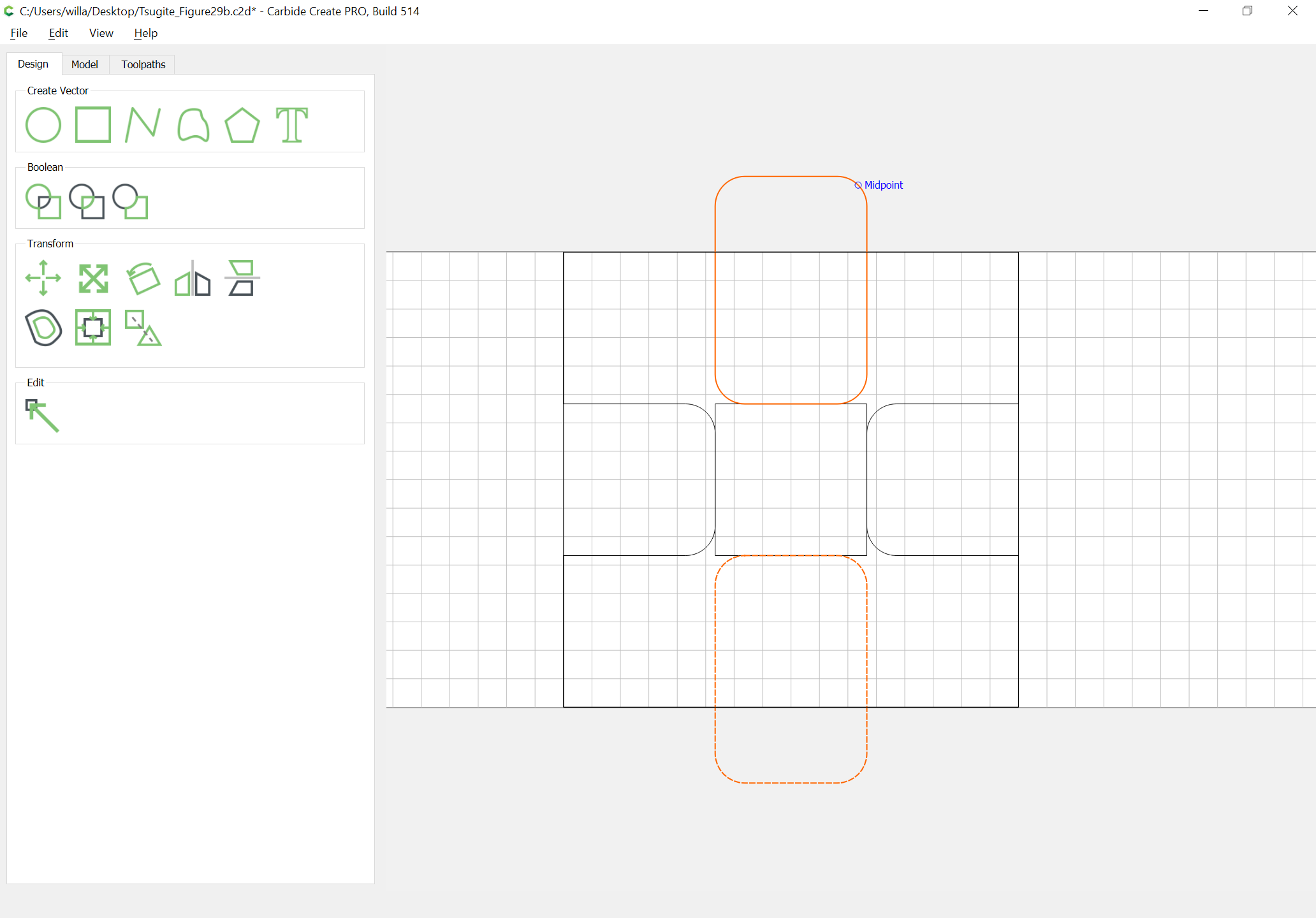
Duplicate it three times and rotate and drag each duplicate into alignment:
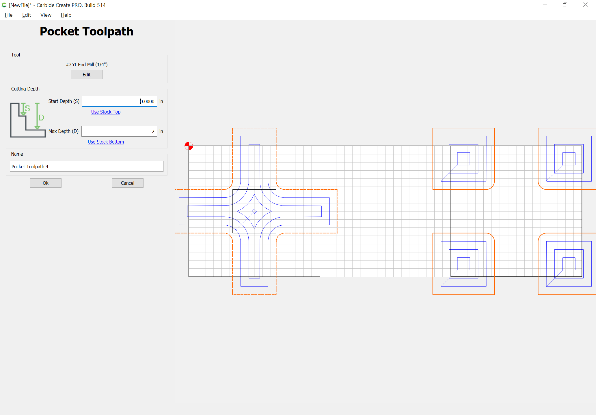
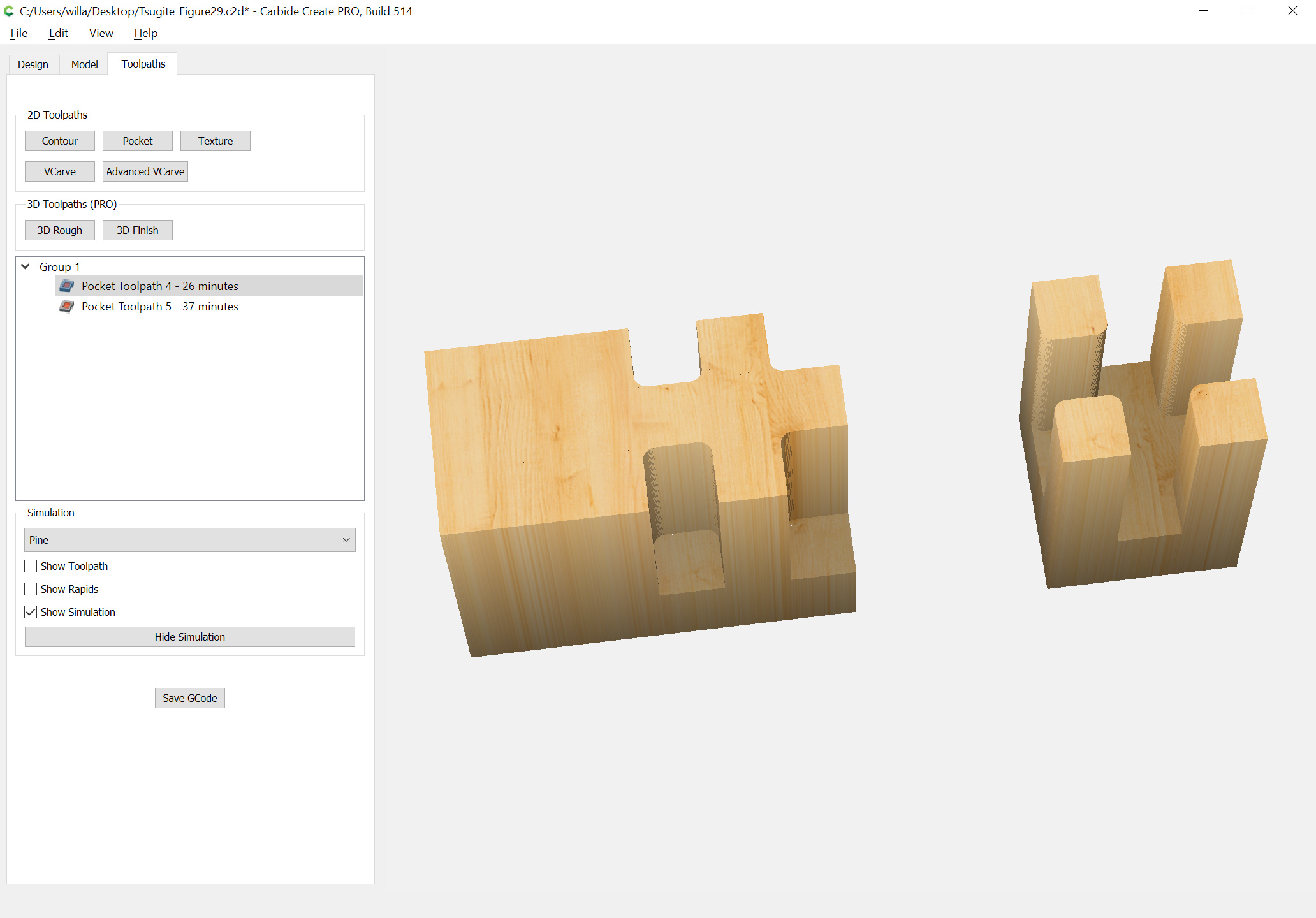
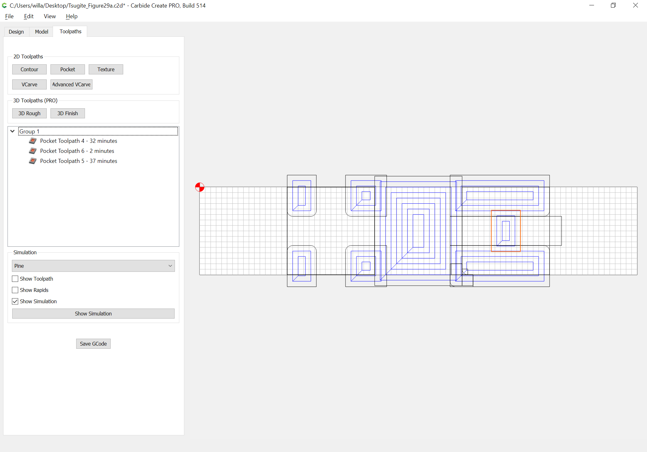
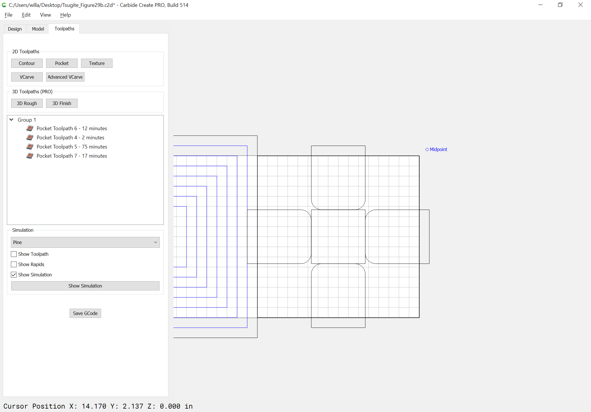
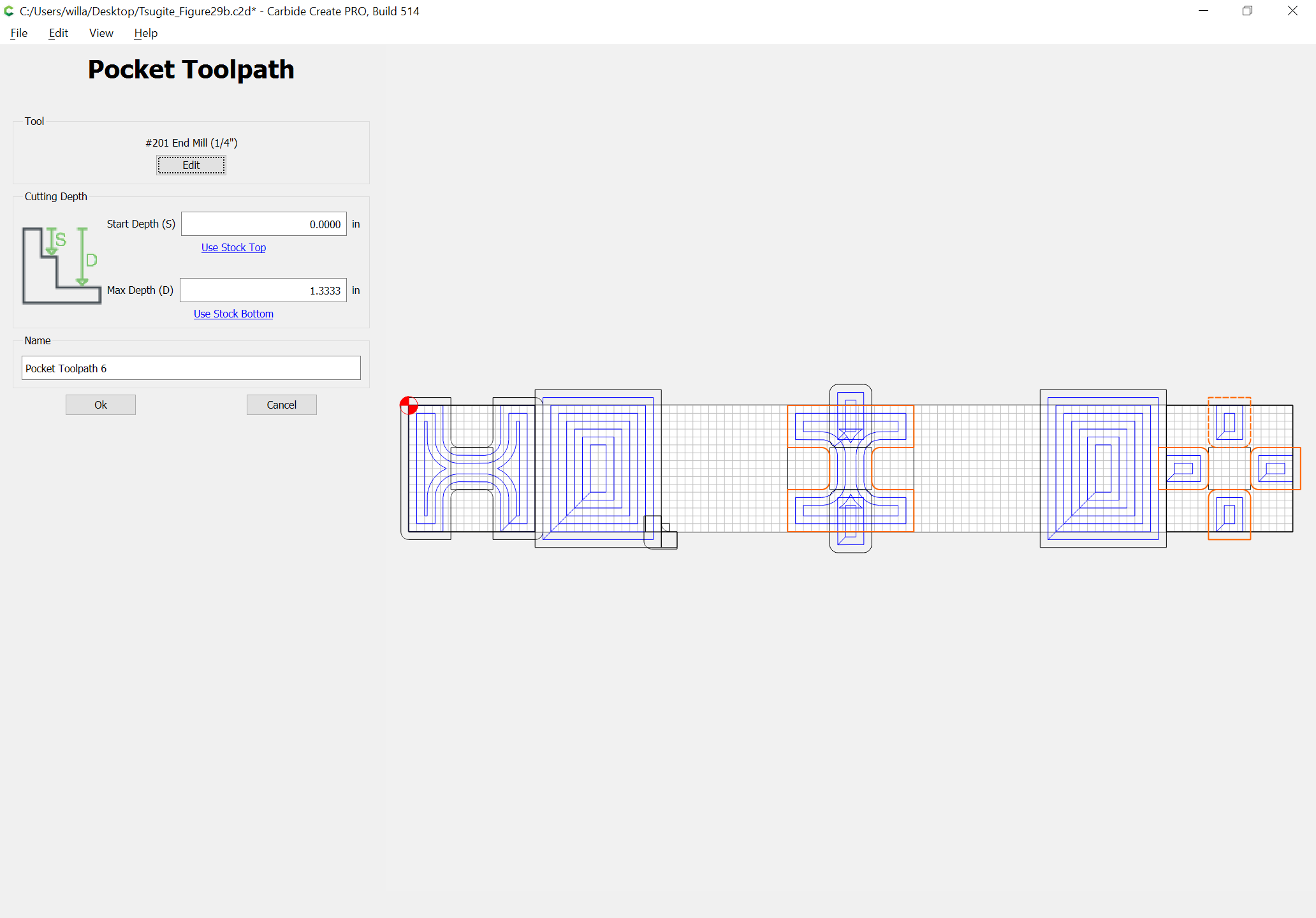
Then set up the toolpaths:
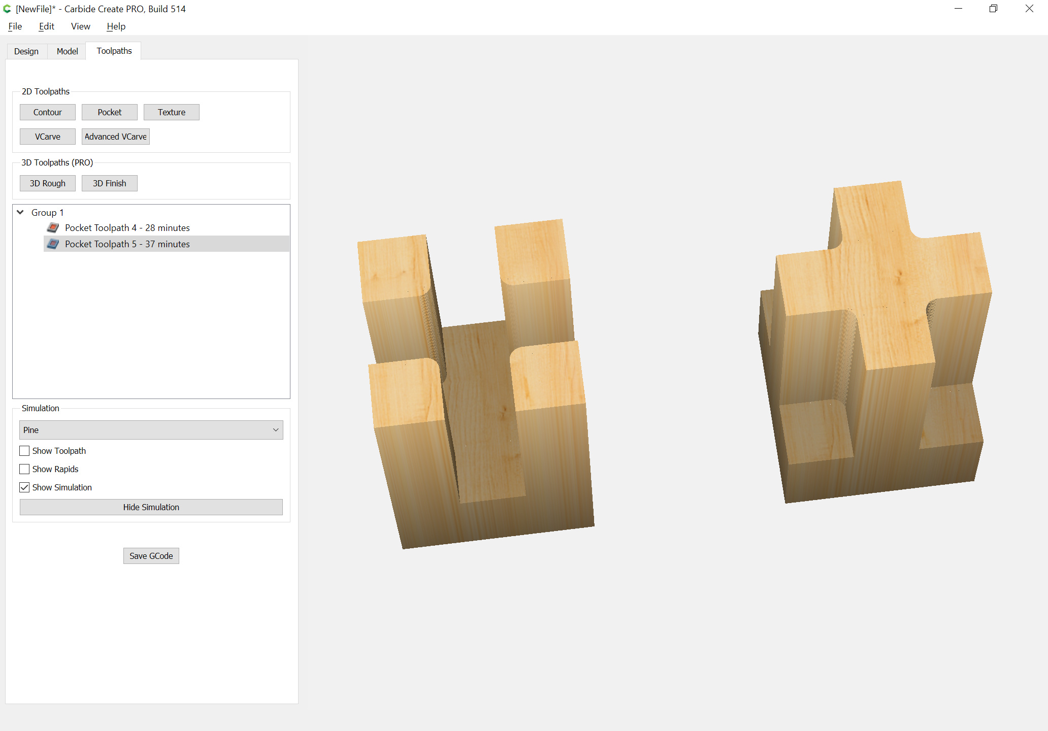
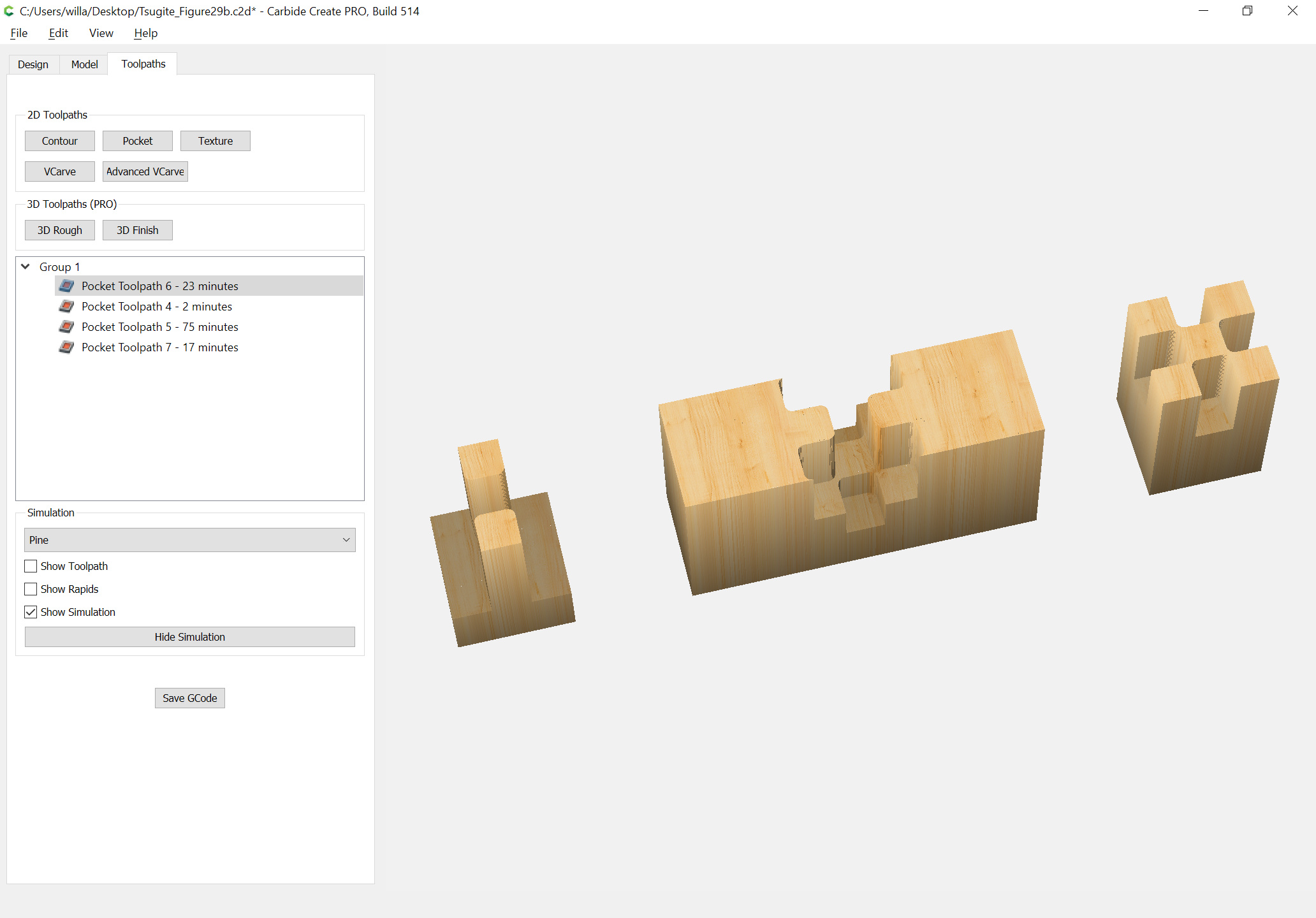
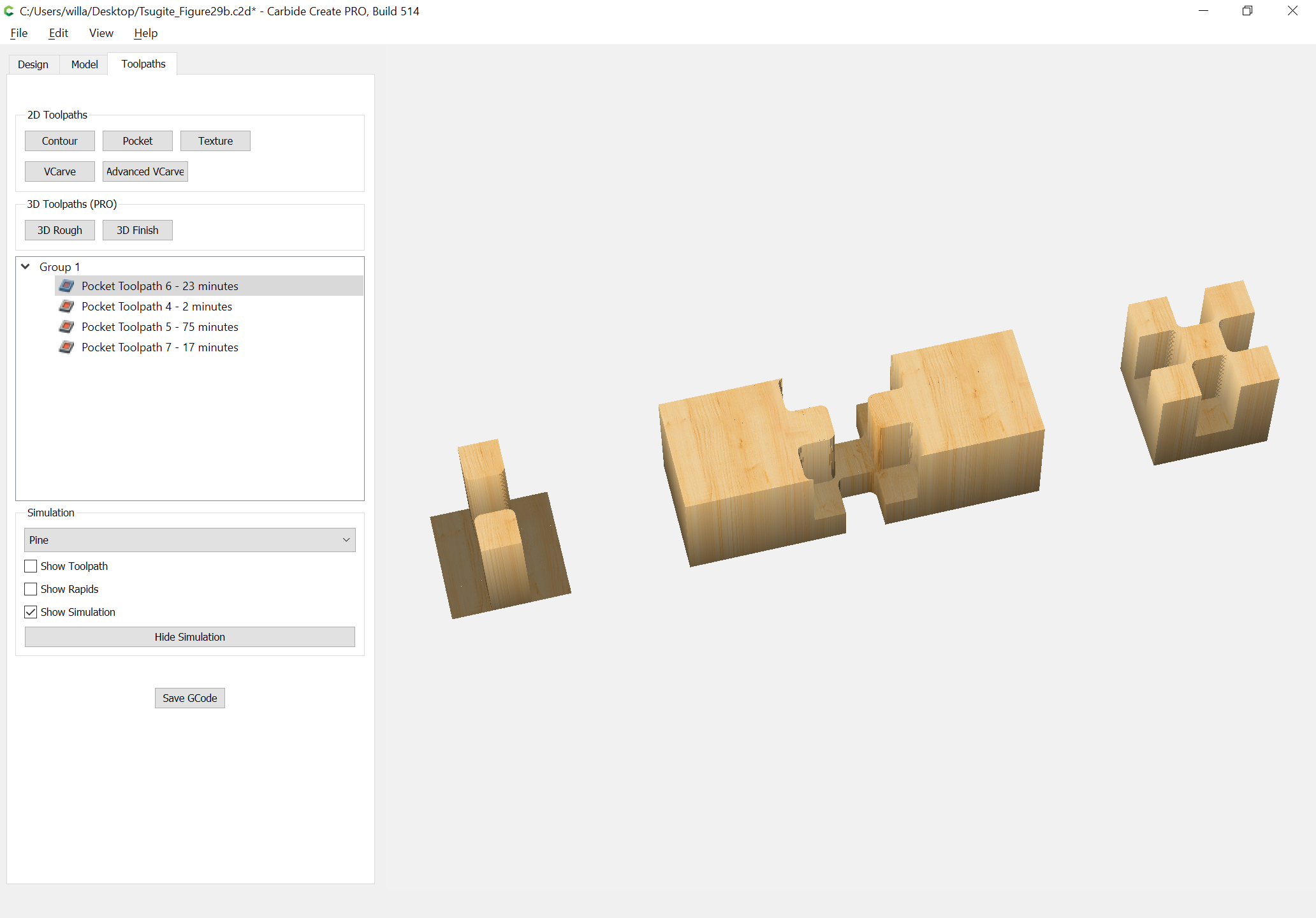
(and change the stock depth to deep enough for the preview and add in some geometry and a toolpath for a better preview):