A twisted little project

It all started with a circle…

And in the end, out popped a twisted little result:

Done on a Nomad. I took a challenge, as “the only way to machine a Mobius strip is on a 5-axis, like those guys Make featured”.

Material: Poplar
Size: It will fit in a 70mmX70mmX25mm box
Thickness of strip: 3.5mm
Time: about 3 hours (could have been faster, but I reduced the tool engagement for reason of paranoia, for some operations. Probably didn’t need to…)

Details to follow if y’all are interested (about 250 screen shots and process pics to sort through. Though the model is easy in Inventor or Fusion360, setting up the machining operations is actually rather a trick)

13 Likes

That is so cool. I’d love to try one in aluminum on my SO3XL. If you’re willing to share the Fusion file? I’ll scale it up a bit.

1 Like

It is in Inventor. When I get the chance (next couple days) I will post the details, but it will take a little time to winnow down the screenshots and photos. I have WAY too detailed of a record.

The technique is the same in Fusion (same CAM engine, and the model build is similar, except Fusion streamlines the relationship between a part and an assembly, if you want it to) as there are no advanced tools used.

2 Likes

Really cool!
Can you share the IPT file?

Ha ha, look out, I’m the proud owner of a shiny new Pentax K70 just itching to document new projects! (As soon as I learn how to use it, that is).

1 Like

would love to see a write up of how you designed and machined this… looks great!

This will be a bit of a long read, in a number of parts (day off from work, so I can do a bit of photo culling), possibly with too much detail. The strip is pretty much the standard form seen in math text and as an example in Mathematica for parametric surfaces, and is also shown as a surface form in one or another of the Autodesk tutorials. Here, since it is being made as a physical object, it is modeled with thickness to form a solid.

Starting with the basic model:

Modeled using Inventor, but I also ran the model up in Fusion, but not the CAM side.

We start with a circle on the x-y plane:

In this case, 25mm

Renamed it “sweep path” then started another sketch in the x-z plane. Tilt the view so I can select and project the circle from the other sketch, then put in two construction segments starting on the circle, one up and one down. Then constrain them to be equal.

Put a circle at each end and constrain them to be equal. I set the size of only one.

and dimension the overall width of the strip.

Put a line to either side

make them tangent to the circles

and trim at the tangencies

Last, cut out the un-needed parts of the circles to form a single closed loop to act as the strip cross-section

and finish the sketch

Next, the magic happens…

1 Like

Now, the cross section will be swept along the circle to form a solid.

Select the profile

and the path (the circle from the first sketch)

And here is a ring. But it isn’t a Mobius strip. That is handled with the twist option. This can be a bit weird. It appears that the ends MUST match exactly when sweeping on closed path, or it will fail. Any asymmetry in the profile will show now. Set the twist to 180 degrees (or 360, or 540 for an extra-fancy version)

And here it is.

Note that inventor remembers where the seams are. This is important later.

1 Like

Now, to set up reference geometry so that the part can actually be made. First, a base plane:

The plane is parallel to the x-y plane (selected from the origin block), but at a distance of -13mm, so it is just below the final part.

And then a sketch is made on this plane to provide a reference point outside the body. This will be on the bed of the machine. It is not critical, but makes it easier later when magic happens.

2 Likes

The astute will notice at this point that the model is simple in the z direction. Simple in the mathematical sense: any line parallel to the z-axis intersecting the part will enter the volume and leave it without re-entering it again. This is not true parallel to, say, the x-axis.

If the part is NOT simple in some direction, then it will require either much more involved setups or a 4 or 5-axis machine. This is essentially the same condition required for the flip-jig, but this is machined with no tabs, holes (other than the obvious one) , or special features to support the part. The reason is this:

2 Likes

That acts as a support to machine the second side, and is why the base plane is there. Again, it can be done without the base plane and external reference, since the second side machining is done using the same reference frame as the support, but it makes the stock size a non-issue.

The support is done as a derived component. It inherits the coordinate frame and changes to the base component will reflect through automagically.

I select the base component, and make sure that sketches and geometry are included as well.

Now, to get a form where the base can be extruded. It seems like it should be easy, but the geometry here confuses Inventor (and Fusion) if some help is not given. We are going to remove some faces so Inventor has clear surfaces to bring the support up to.

Remove the “upper” face, and also the TWO oval faces where the surface closes.

to get this:

Now a sketch on the base work plane:

Projecting the appropriate edges to the base plane allows for the support to be extruded up to the bottom of the Mobius strip without confusing Inventor. Removing the faces lets us get the edges without issues.

Two edges are selected.


to get:

This will be projected up to form the support structure.

1 Like

Extrude:

To Next

And we have it. Almost…

Now to get rid of the remains of the original strip. This needs to be done by removing the surfaces. This keeps the imported solid in the development.

remove the three remaining faces of hte original strip from the model

and we have a support

2 Likes

Last is the setup for the second side. (note that in building the support model, I didn’t flip the part. Symmetry is a wonderful thing…)

This is done by putting the support and the strip into an assembly to reflect how the part will be fixtured during machining.

So, make a new Assembly and bring in the fixture:

Ground it at the origin to insure that the coordinate system will be consistent (this is a right click option).

and place the strip into it. The common coordinate system due to deriving the fixture makes this easy. Inventor did not want to deal with assembly constraints for this. I tried, and, though I found a way if I ever need it, it is not easy. For setting up a fixture, a common coordinate system is by far the easiest method.

And renaming the point so I don’t forget. (I didn’t think of it earlier in the process)

This is roughly the halfway point. Next is the CAM side. There are three operations (actually four, since I sized the stock on the machine, but I won’t show that)

2 Likes

And now, the CAM.

The first side of the strip is from base stock. I machined the stock to size on the Nomad (not shown) to insure square edges to ease alignment when mounting in the fixture later.

The setup is straightforward:


Note the selection of hte reference point as the origin. This puts z=0 ON THE MACHINE BED.

I sized so that the ref point was outside the stock. This is not that important, but, again, is convenient.

The major stock removal is done with an adaptive (trochoidal) operation. Square end tool, running fast and deep.

Select tool (yes, I have a larger library than this, but this group has the ones I use most):

Note the speed and feed:

I know where the part will be, there are no extra fixtures or clamps to clear, so the heights are low to reduce extra vertical motion. This becomes more important with taller parts to keep from losing position by trying to overtravel up to make clearance.

Small load (1mm, 30% of tool diameter) but large engagement length. Gets a lot of life from the tool, makes large chips rather than dust, and maximizes material removal.

Left 0.3mm for the ball end later. This is enough for two passes with the tool maintaining engagement rather than skipping and digging, but keeping low load to control deflection due to the long stickout.

Keeping feeds high when tool isn’t engaged, but I later reduced the staydown to 40mm and 70%, rather than 50mm and most, to reduce going the long way around when not cutting.

And the toolpath simulation. Some of the long way 'round is visible on the far side. Most went away when I made the changes to the stay-down, and the machining time dropped about 10%

And the machining sim:

1 Like

Next, the finishing with the ball end:

Similar, so no detailed explanations…

Again, adaptive

Work from previous operation to avoid machining air too much. This is just to remove the steps

Shallow machining enabled to smooth the flatter areas, and leave 0.1mm for the final pass. There is so much flat area, leaving more tends to get the ball-end vibrating. They center cut, but it is less than ideal on a flat area.

Toolpath and sim:


Finishing using a “morphed spiral”. This is quite a nice strategy for this.

Note the small stepover (20% of the tool diameter). Less than this does little good to reduce cusps, but will reduce the spacing of the visible tracks. If the part will be finish-sanded, all you really get is more machining time. I would have gone larger on the stepover, but I wanted to be able to drop into the fixture later with no sanding/postmachine operations.

The fixture is similar in machining. In fact, once the setup was done, I copied the operations directly. All one need do is check them and adjust the geometry selections.


The second side is similar as well, and, again, I copied the operations. Later, I reduced the tool engagement to 5mm for the first operation to reduce the risk of pulling the part off the fixture. The setup is similar, but I made sure that the fixture was properly selected (this is an option with an assembly) to insure the tool did not hit it. That shouldn’t be an issue with this setup, but if I had messed something up, the CAM engine would cover me.


That is the CAM.

Next: actually machining it.

1 Like

The machining is pretty straightforward. The material was taped down to a convenient wasteboard (I have maybe 20 of them in different states of use) using 3M 467MP. This is a plain adhesive of precise and uniform thickness (0.06mm) and it holds like crazy. It has a peel off backer on both sides, so all that is left on the work is adhesive, unlike, say, carpet tape.

Just pics here unless there is something non-obvious

First setup:


Note that I left a skin (0.5mm) at the bottom. This did help stabilize the part during machining, but it is mostly for help in lining up when placing it on the fixture later.

1 Like

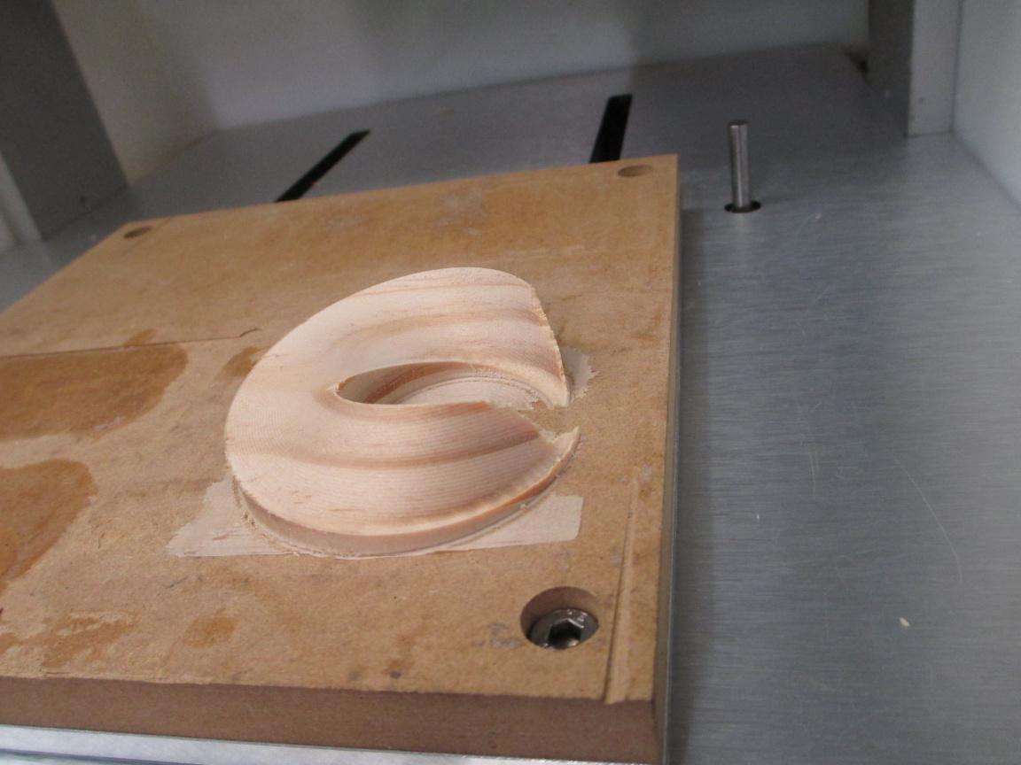
Machining the fixture. The wood is from the scrap bucket.


and mounting the part:

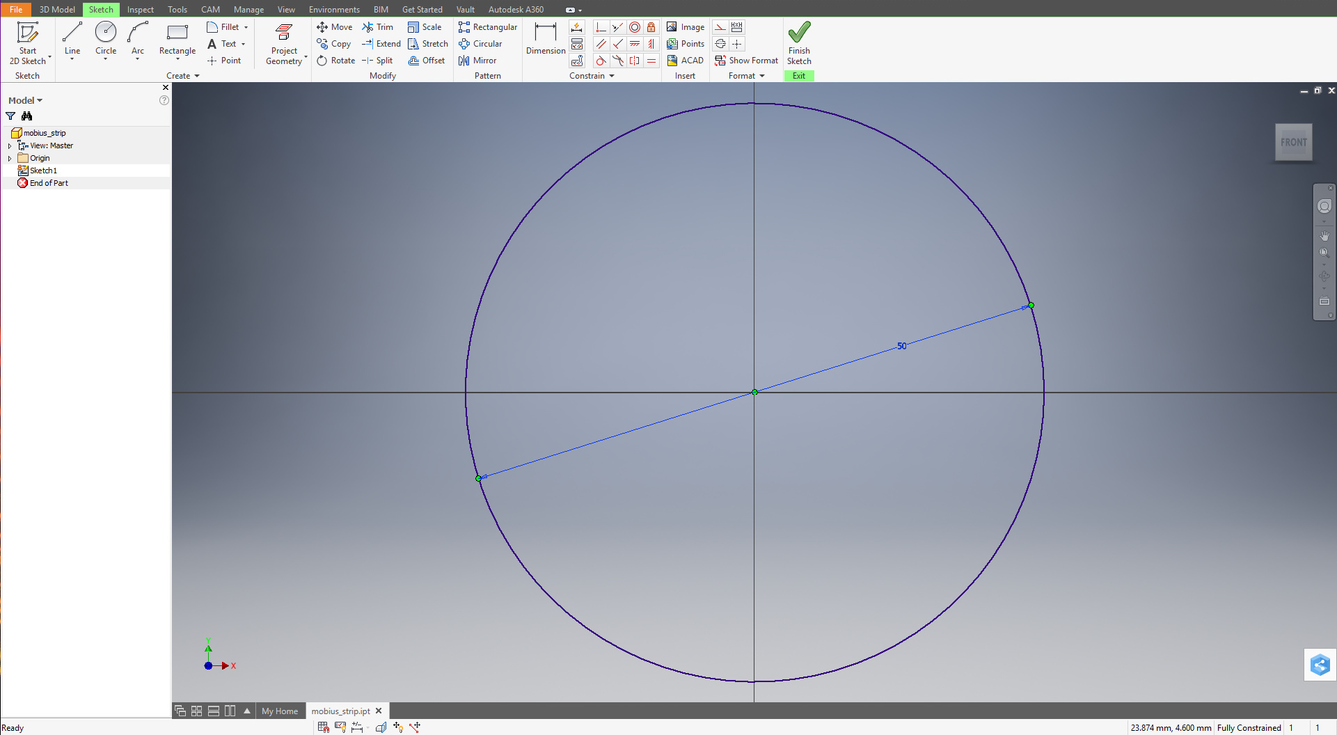
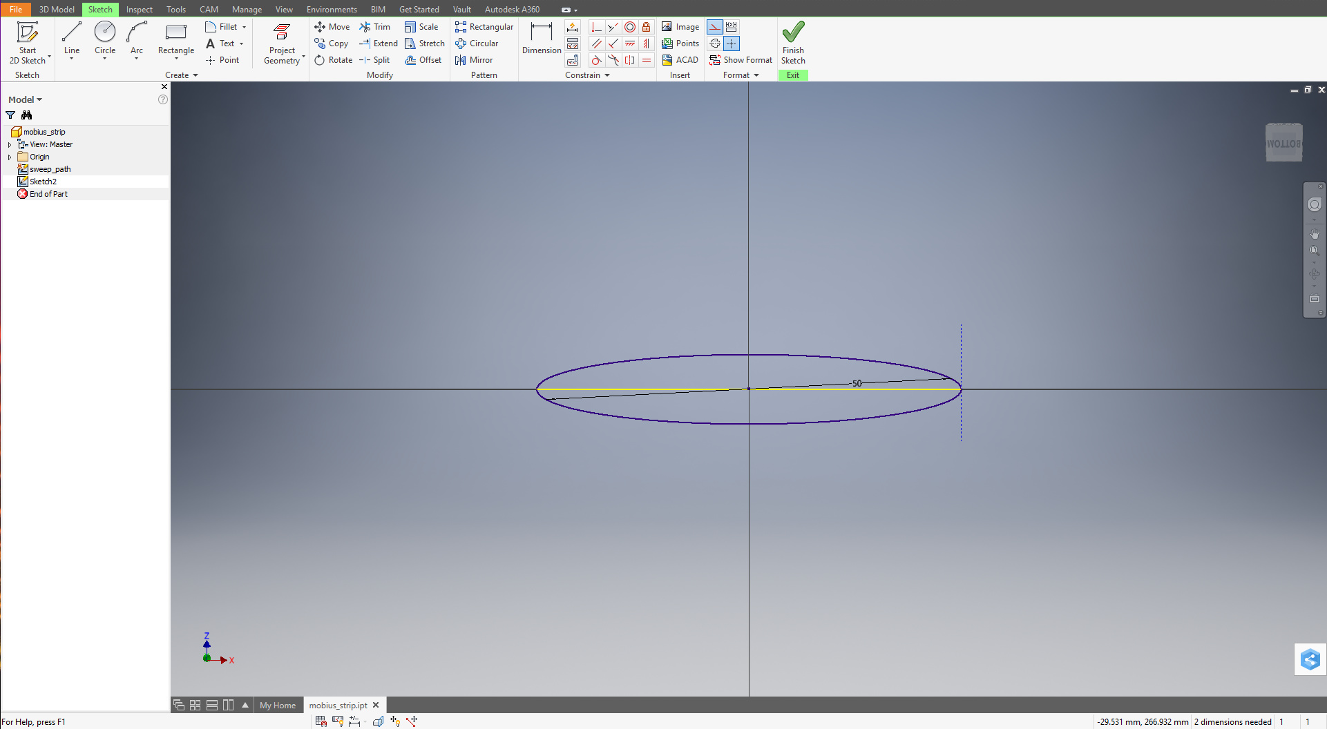
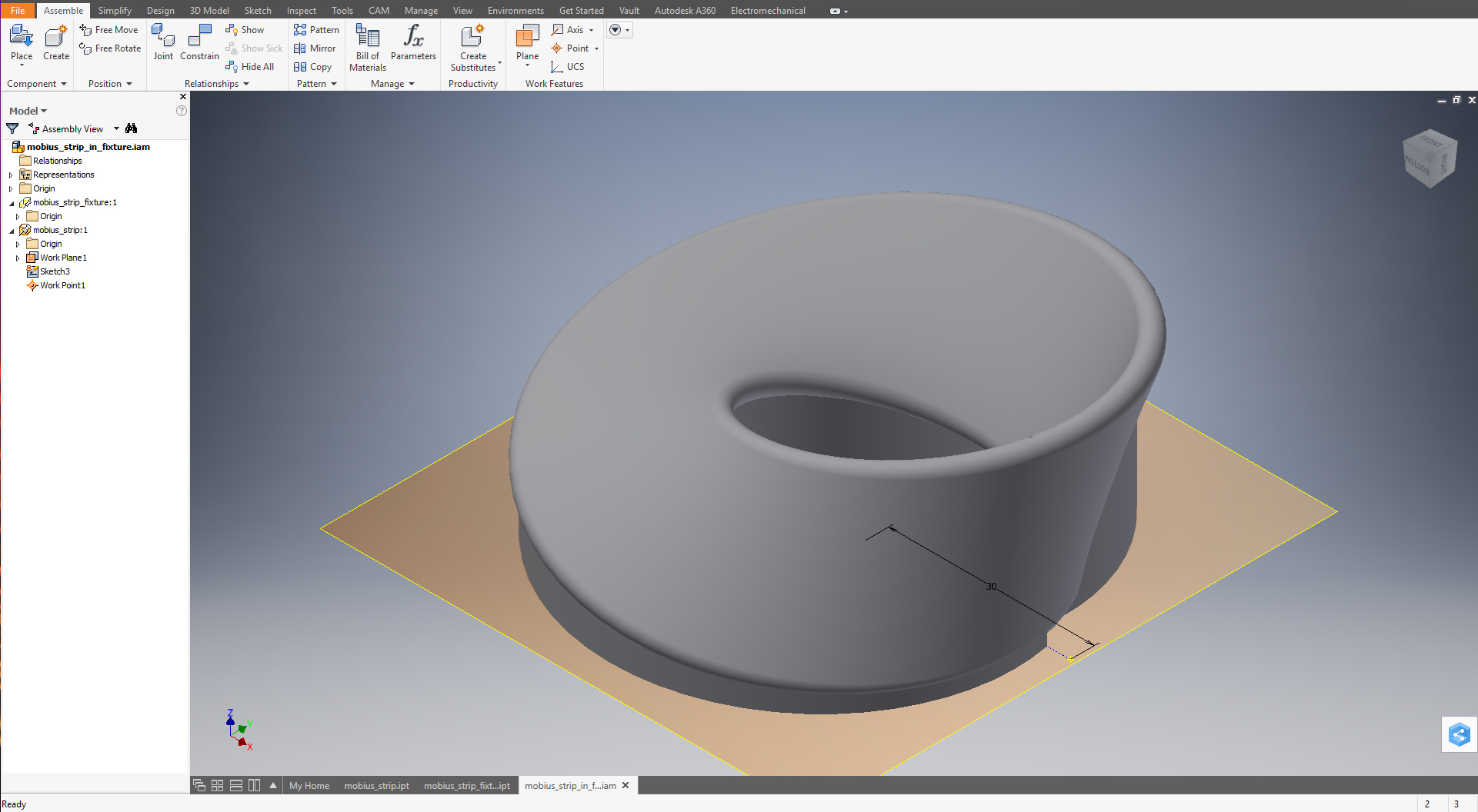
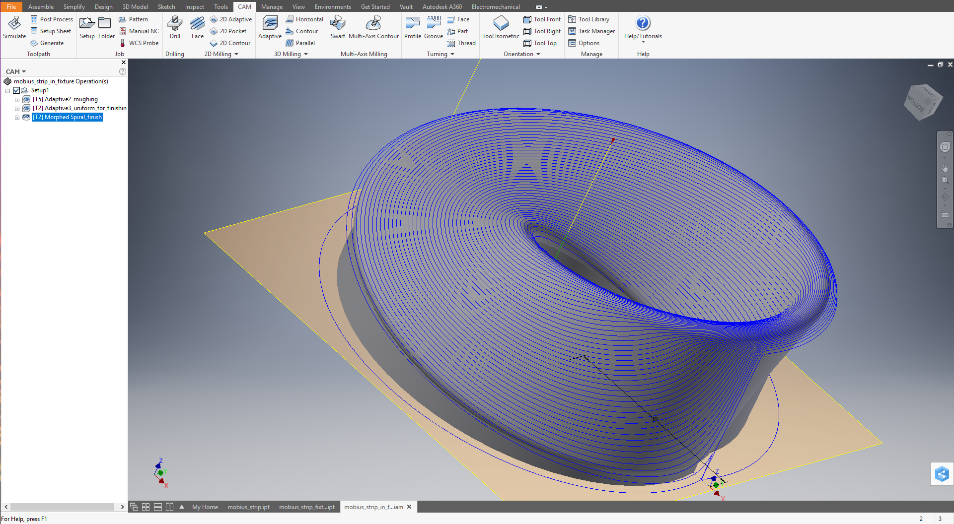
This is where the residual bas came in. I mounted the rough stock, then sized it. Then machined the form without moving it. This left the edges of the stock lined with the axes of the machine, and the axes of the model.

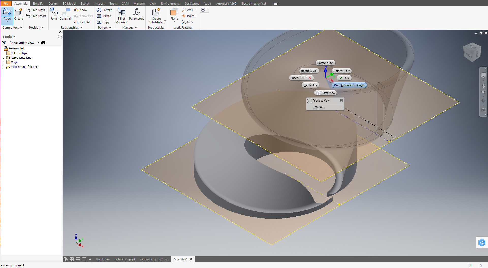
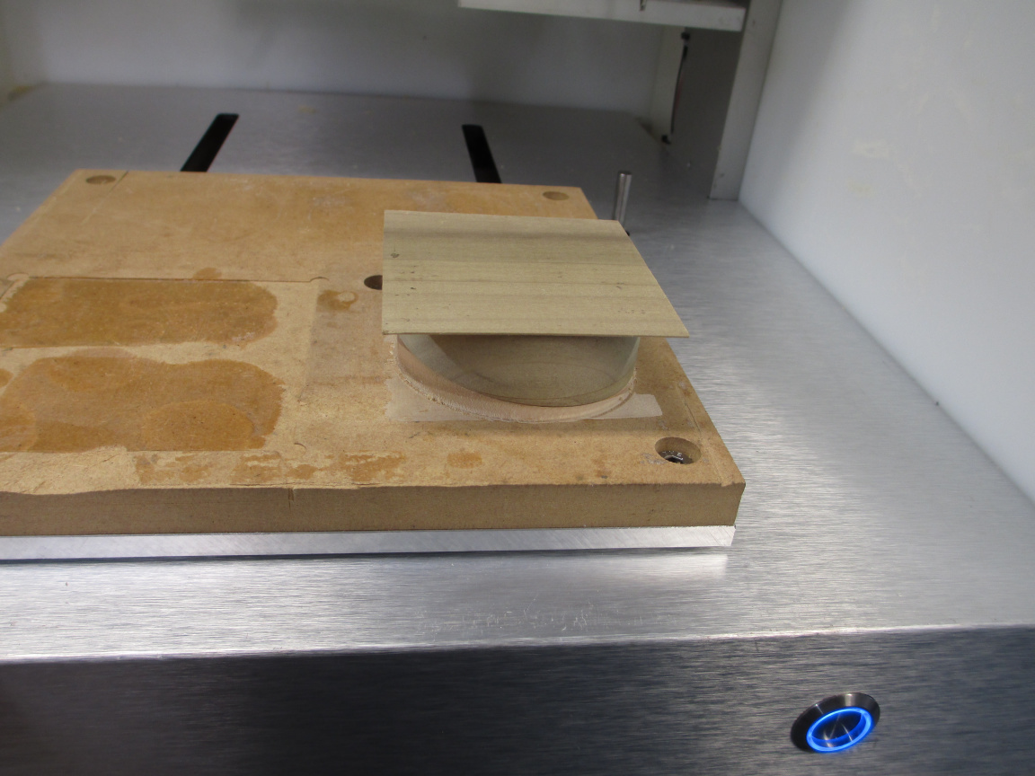
To mount it here, I used several small pieces of the 467MP, making about 1000mm^2. This is not a lot of area. To get the most out of it, ALL of the adhesive nees to be in good contact. Just dropping the fixture and wiggling it a little lets it find its home (the ‘hook’ at the bottom where the radius of the edge seats insures this… it is positively located for all degrees of freedom), but once the adhesive is there, adjustment is not possible.

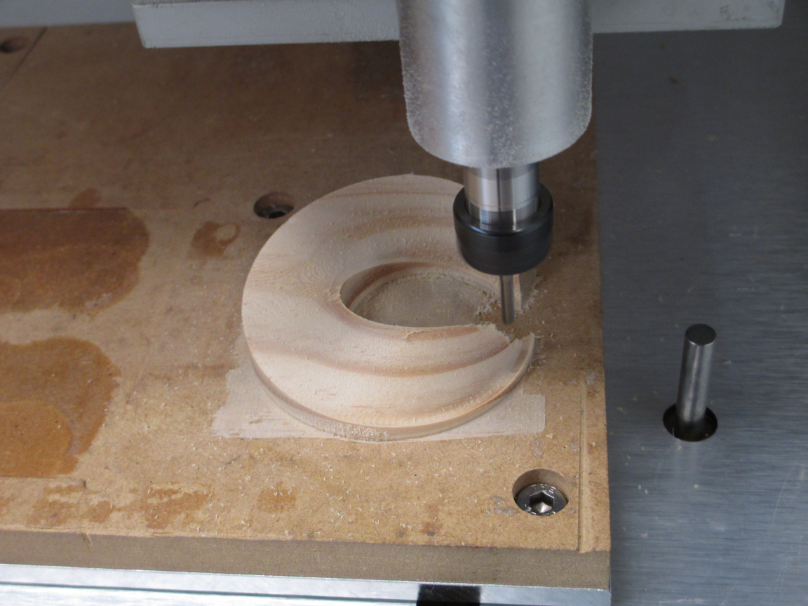
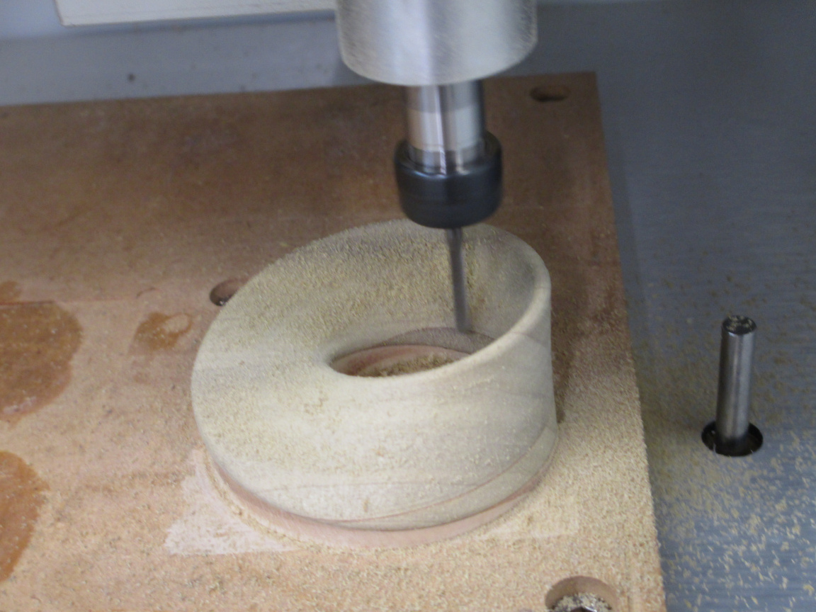
I rehearsed the placement several timed, applied the adhesive, and set the part. Then, with a gauge pin in the collet, a scanned the spindle along the edge of the original material (I could have used an indicator in this case, but this was easier) and felt for constant clearance with a 0.5mm feeler. If not properly mounted, the clearance would change. It was constant to within 0.03mm both in x and in y travel, so I presumed a good mount.

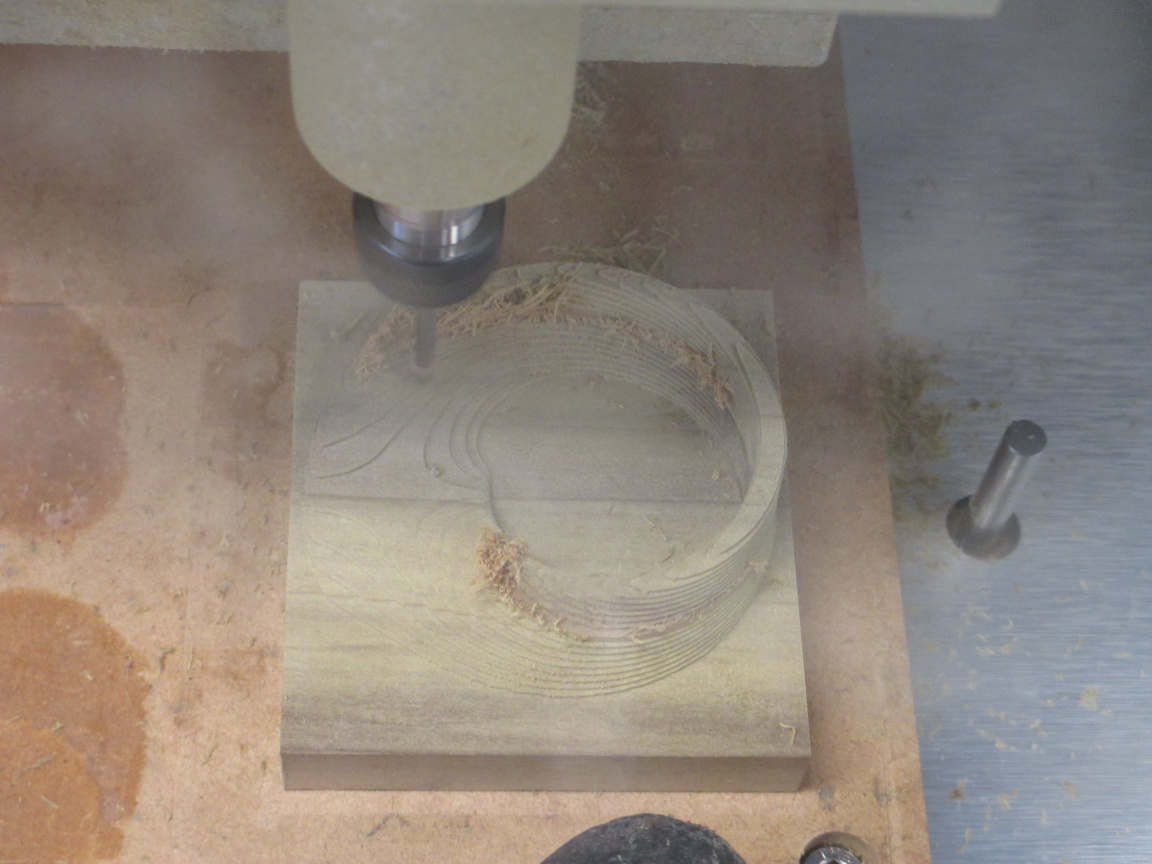
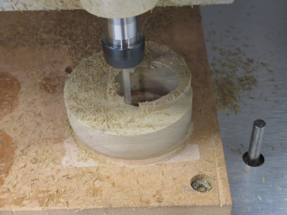
Light pressure for a few minutes to get the adhesive fully tacked in and away I went… Before starting, I upped the z zero about 0.03mm and shifted the y zero as well to partly compensate for the adhesive. Due to the varying angles, this isn’t going to be perfect, but if it was that important, I would have offset the surface by 0.06mm in Inventor.

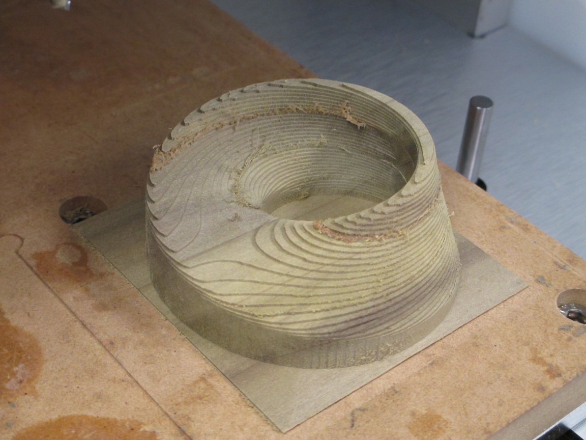
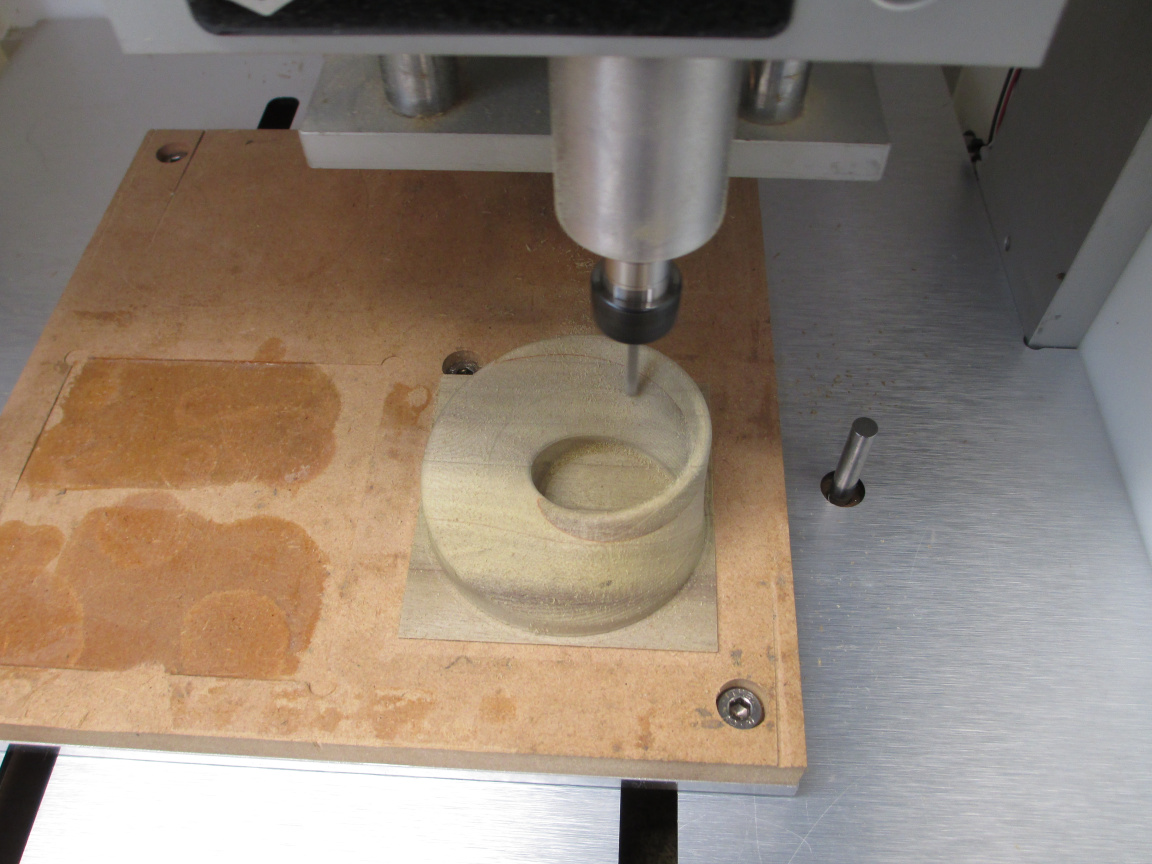
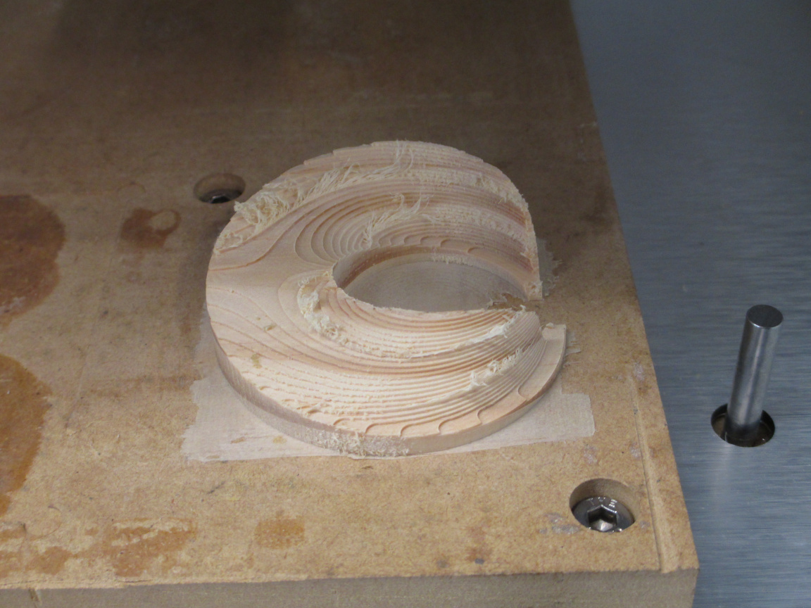
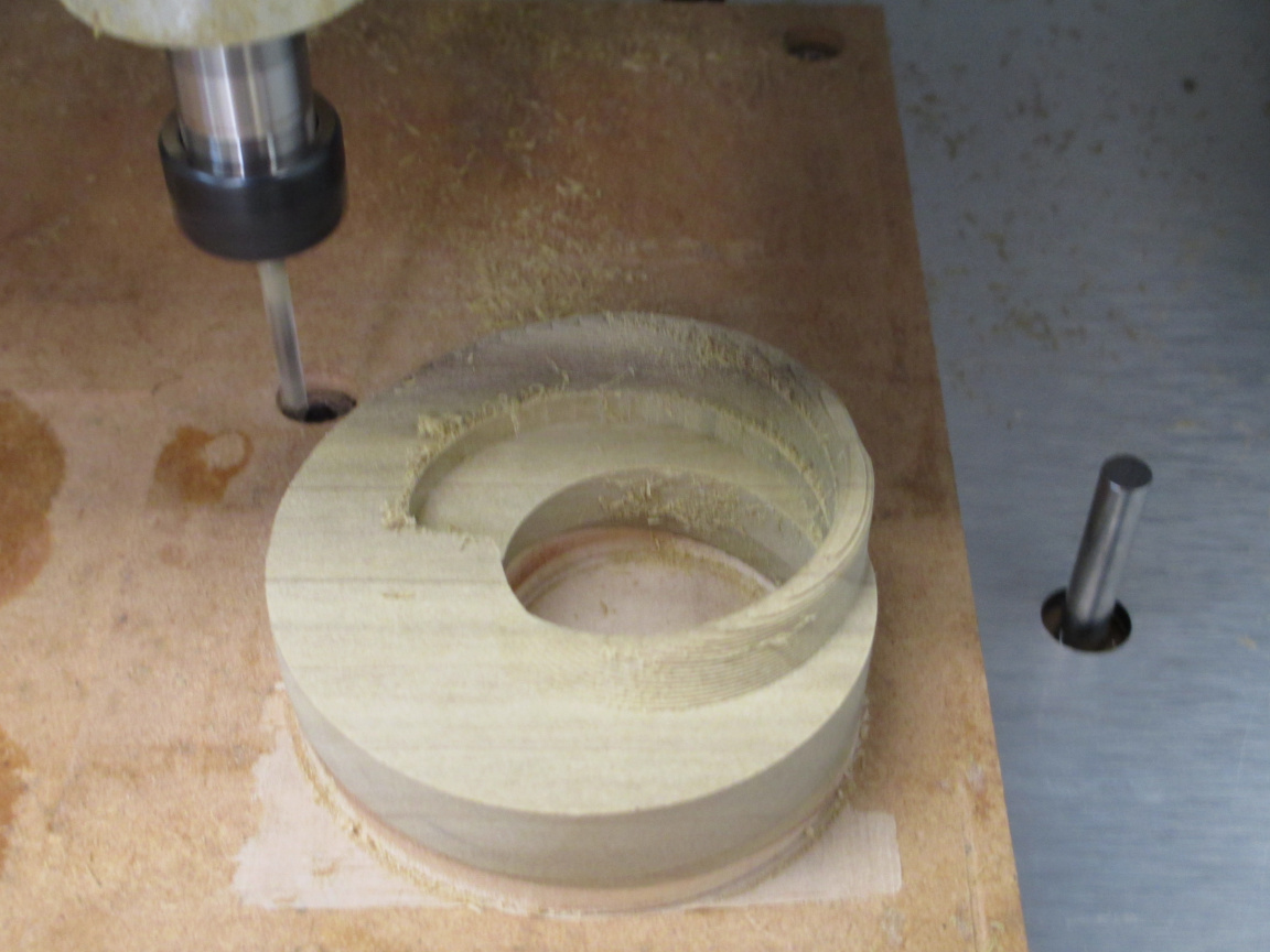
The skin was gone quickly. Much time cutting air, as I did not bother modelling the material that had been removed but the first setup. I could have done so, but it would have been more time to do that than the machining time saved. For a production job, yes. For a one off, no.


The supervisor in place on my lap. He doesn’t mind the sound of the mill or the vacuum.

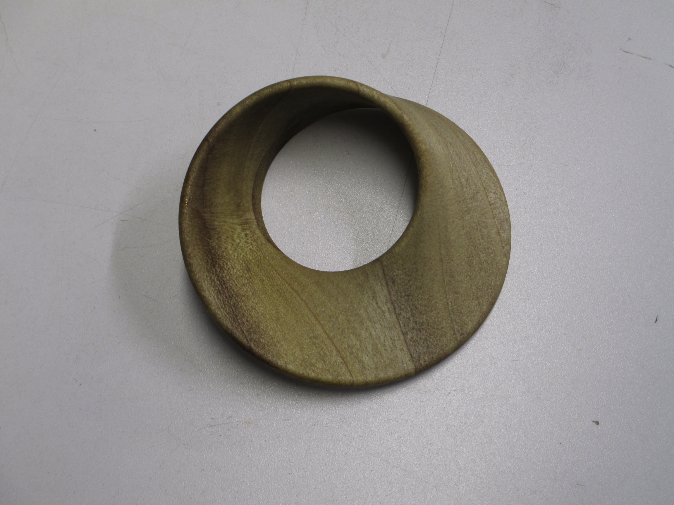
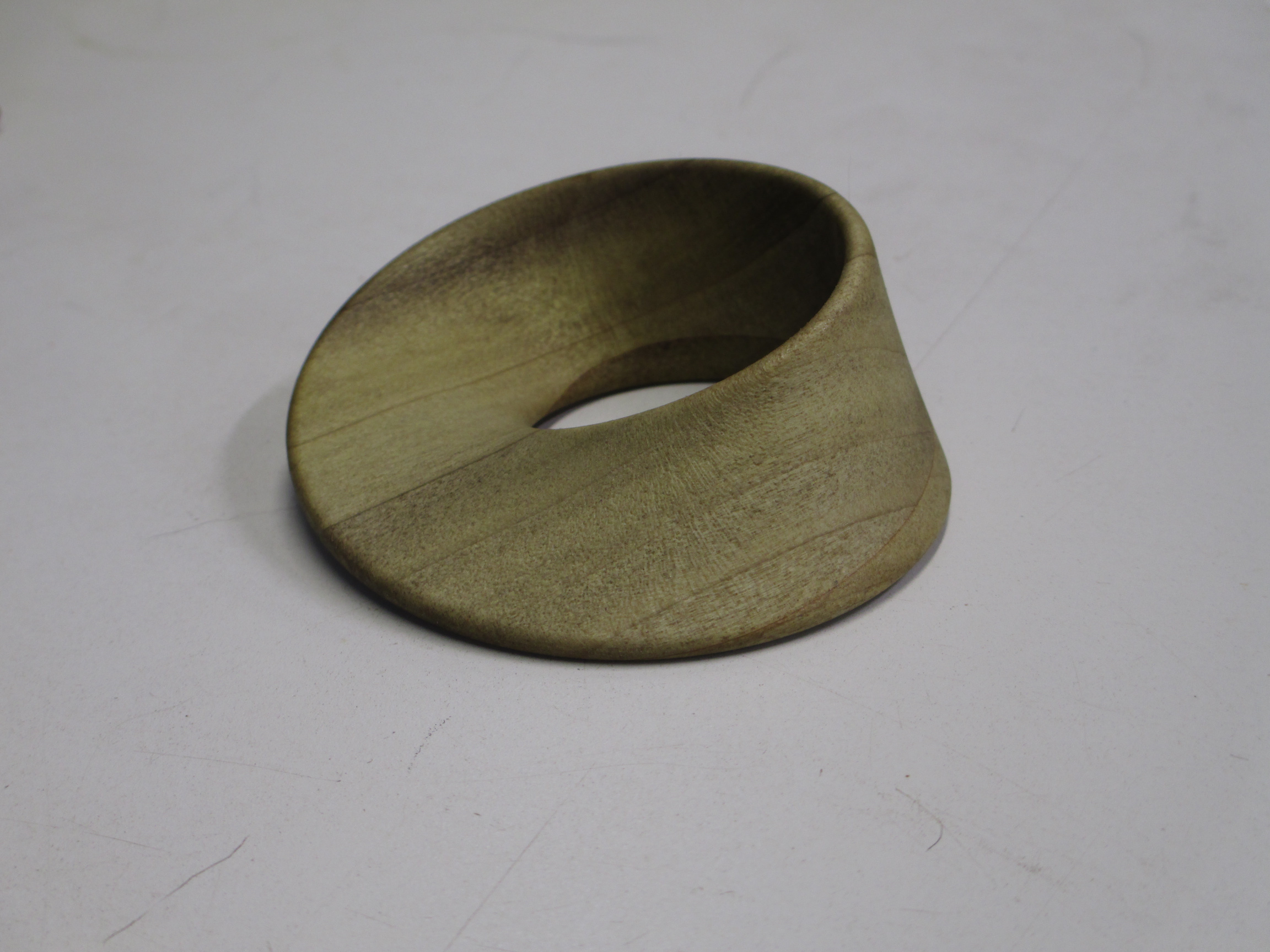
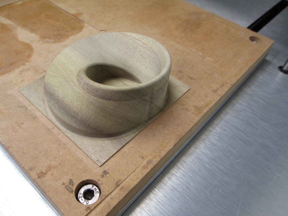
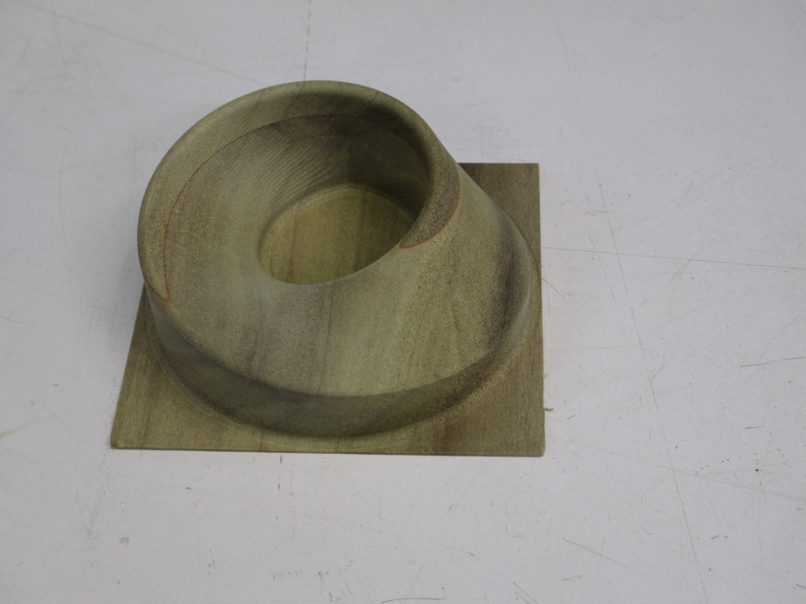
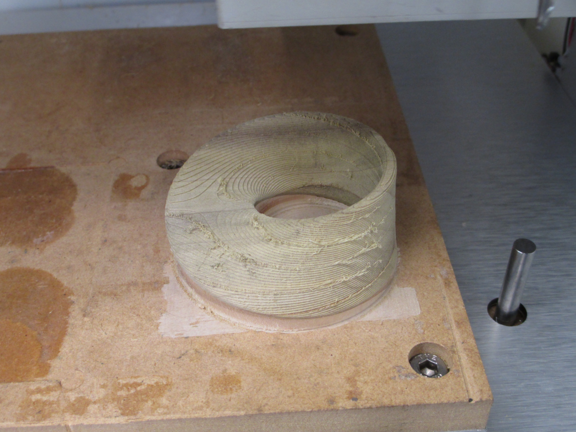
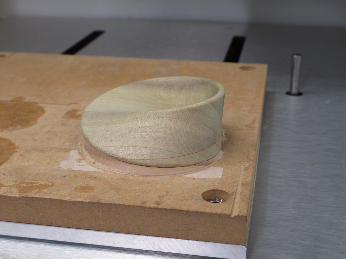
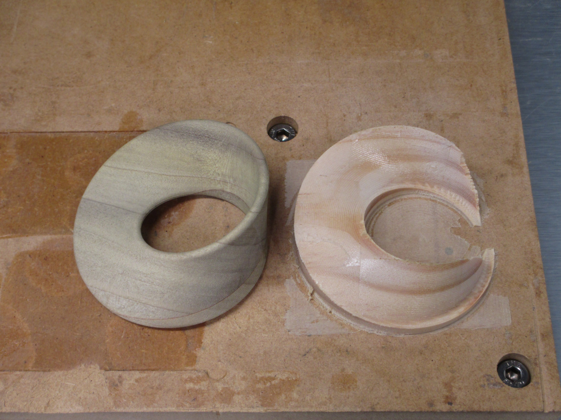
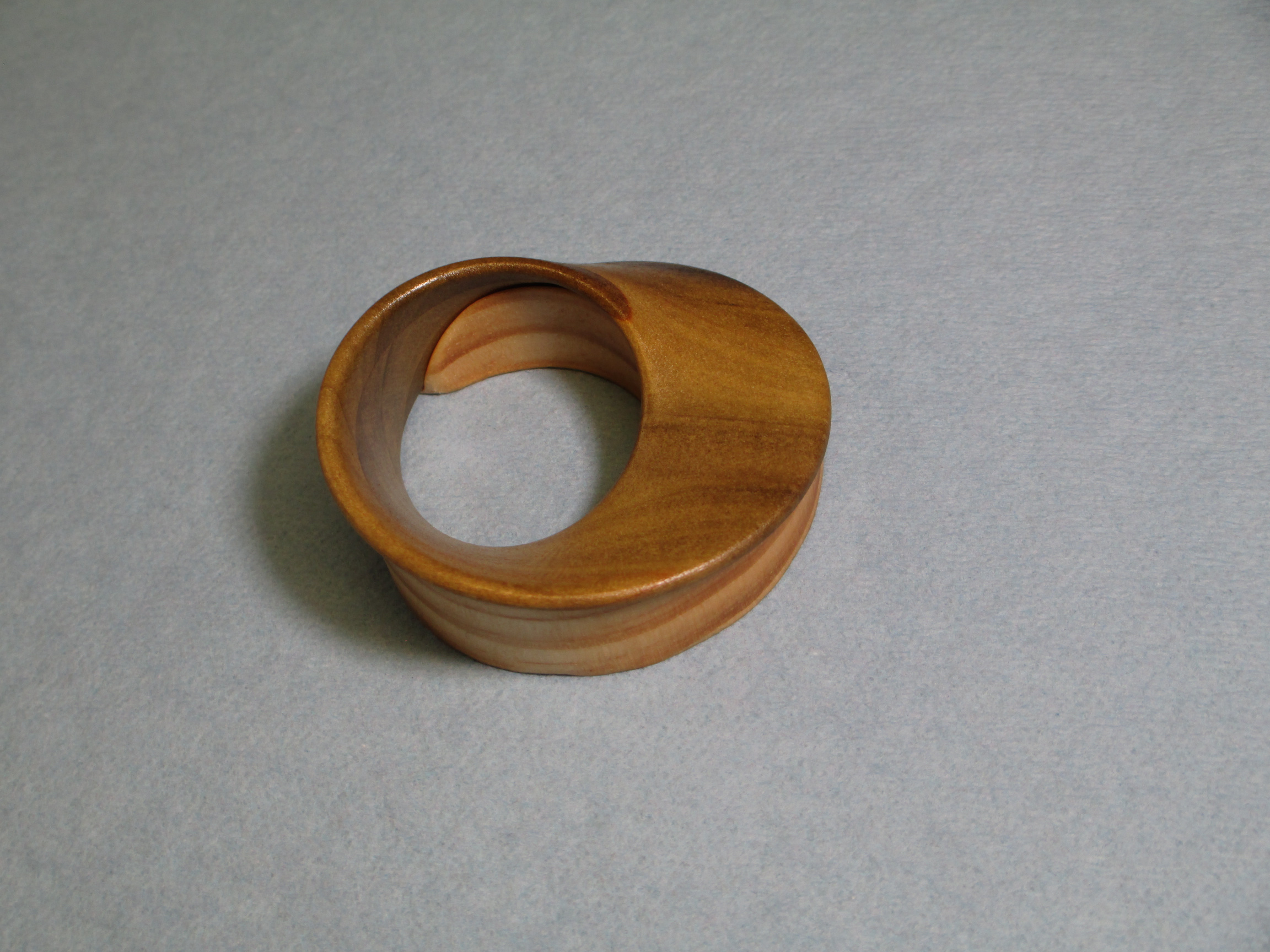
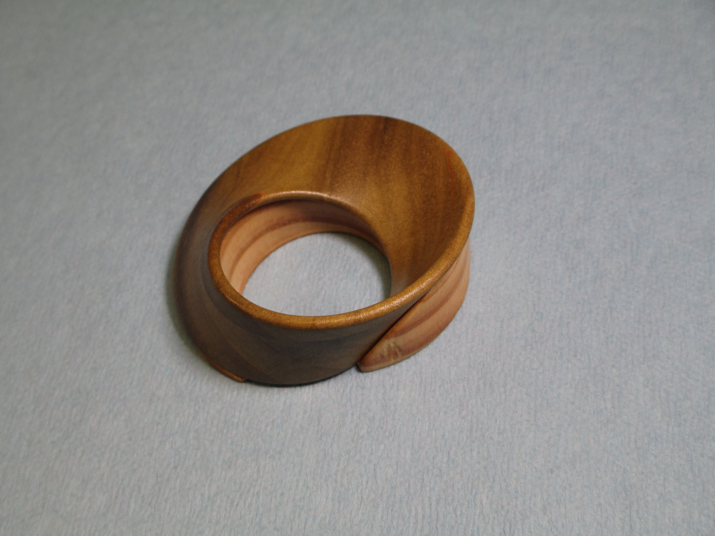
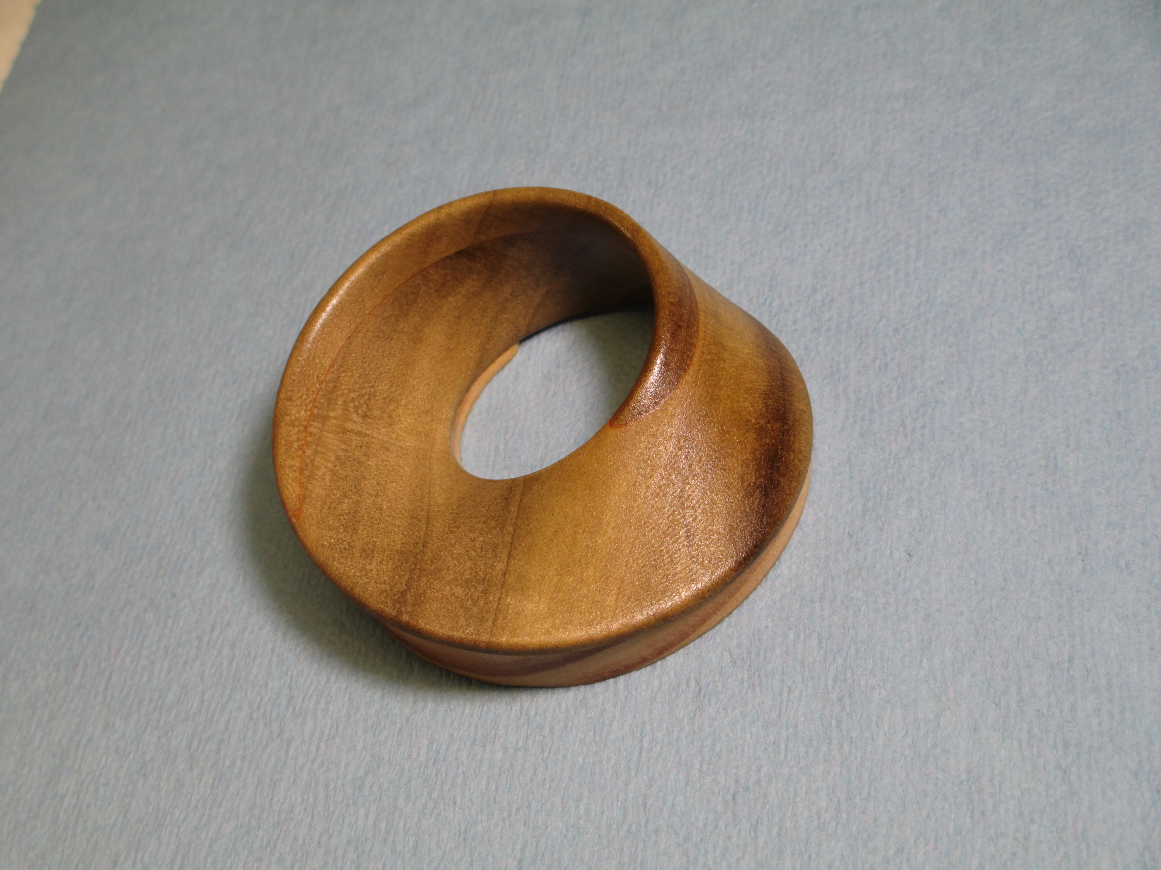
Removed from the fixture. Residue of the adhesive is visible on the fixture.

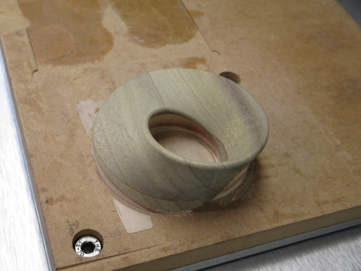
The fixture made a nice base once I cleaned up all of the chipping and smoothed the corners. You can see I hit the z-axis zero just about dead on, as it machined through the adhesive for the fixture, but didn’t mark the waste board.

And now it is time to go get the supervisor his lunch.

7 Likes

Wow! Awesome write up! Thanks so much.

After light sanding and applying finish: dip in shellac (1/2lb cut) to fill pores, several more coats wiped on, light sanding with 800 grit, and shot with 2 coats of lacquer. The shadow of the finish passes still shows from the right angle. Getting rid of this on poplar (a pretty soft wood) would require substantial sanding.


6 Likes