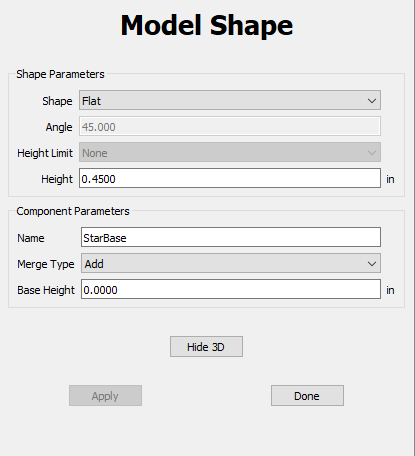
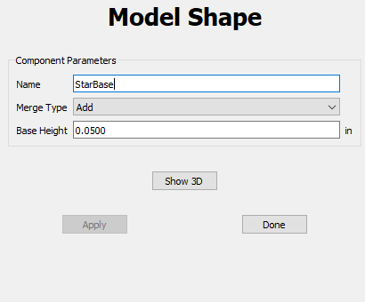
When adding a 3d model there are more settings when creating than you can view adjust after creating.
vs
It would be nice to be able to view all the settings originally entered (even if they can not be modified) as I adjust and tweak to get what I am looking for, especially if it is days later when I come back to this project.
Yup, it can be rather frustrating at times.
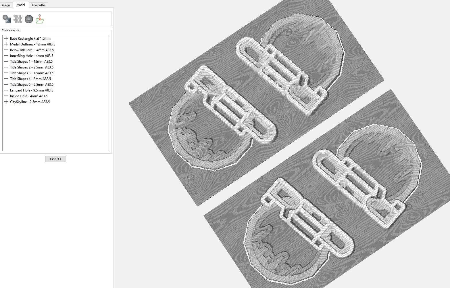
I started naming features with the parameter settings so I can easily re-create the feature later or know what I did.
Unfortunately this doesn’t tell you which vector path was used to create the feature in the first place - usually not a problem until you’ve got so many offset vectors you’re design has become abstract art!
Hopefully one day CC will be able to maintain links between 3D features & the 2D vectors. It would enable greater versatility in the design work flow. But until then…
I do the same. I have components named, “Stars_Angle_45_Limit_0.125_Subtract”
The problem is, once a component is created it is no longer a geometric object, but a grayscale bitmap.
The parameters used to create the component are gone. Only the parameters that can be applied to a bitmap remain. Making them parametric would be a pretty big undertaking.
We’ve been thinking this one through for the last year and we have some thoughts:
We could treat components like toolpaths, where the components are linked up to the vectors so they can be rebuilt anytime, with new parameters. (Maybe these are called “Live Components” or something like that).
For live components, I’d probably prefer to use layers as inputs for vectors, rather than individually selectable vectors because that makes it easier to have project files that become templates.
But, a live component cannot be dragged/dropped/rescaled as a complete object- you’d have to move the vectors or change the parameters for that.
Components that are frozen/locked/flattened into a heightmap can be moved/scaled/rotated, but the fundamental shape cannot be changed after they’re converted to a heightmap. (These would be equivalent to an imported heightmap or STL)
Logically, this is clear to me from a how-to-use-it POV and from an implementation POV. I’m not sure it will be clear to a user off-the-street though. Before we go too far, we also want to make sure that the fundamentals are good on this concept so we can support additional operations in the future.
Glad to hear that upgrades for the 3D module are in the works!
I’m not entirely sure I completely understand your description of utilizing layers for live components, but I get that there would need to be a logical hierarchy of vectors->layers->live components->set components.
In my current usage case, it would have been grand to be able to move/rotate/resize/copy/paste the vectors after creating the components & have the components follow along.
Then after getting the multiple vector copies aligned with the final work material, re-generate all the components which can then have the toolpaths all generated.
Also would be great to see what vector was used to generate a selected component. It gets pretty difficult to know what’s what after you’ve made 4 or more small offsets from the original! Maybe vector ID’s are needed…
You’d pick a layer for a component and all of the vectors on that layer would be used to build the components shape. If you add/remove/modify the contents of the layer, the component can be rebuilt.
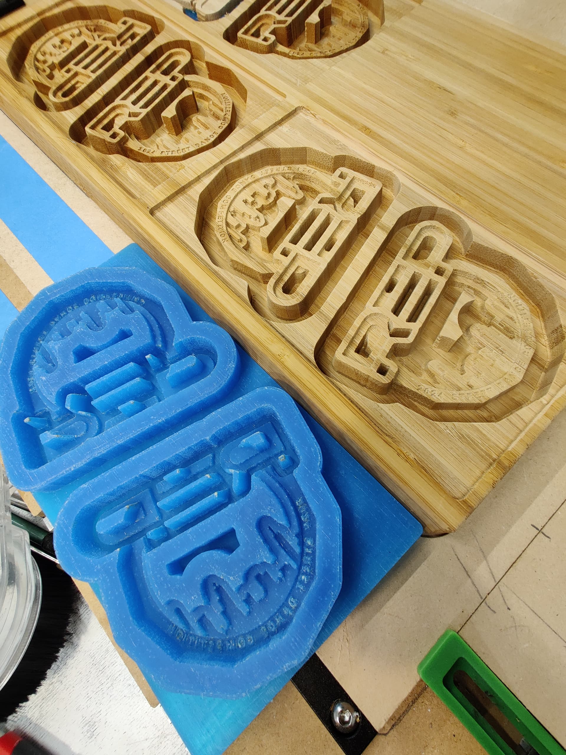
Can you share a photo of what you’ve been making with it?
Ah, that sounds like a reasonable way of dealing with live components.
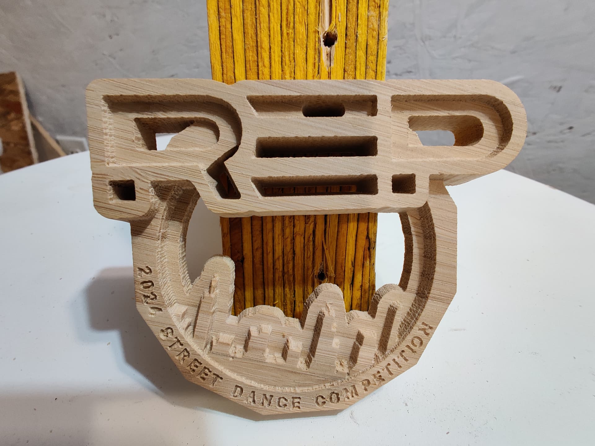
I believe I’ve shared a version of this project file previously with regards to the extra height added during ramping toolpaths.
Creating the initial medallion prototype was pretty simple & easy in CC using vectors & components. The prototype was well received by the client.
But then my troubles started when I had to start thinking about making them in quantity - the rasterizing 3D carving just takes too long. So I started the process of trying to ‘optimize’ the vectors & toolpaths.
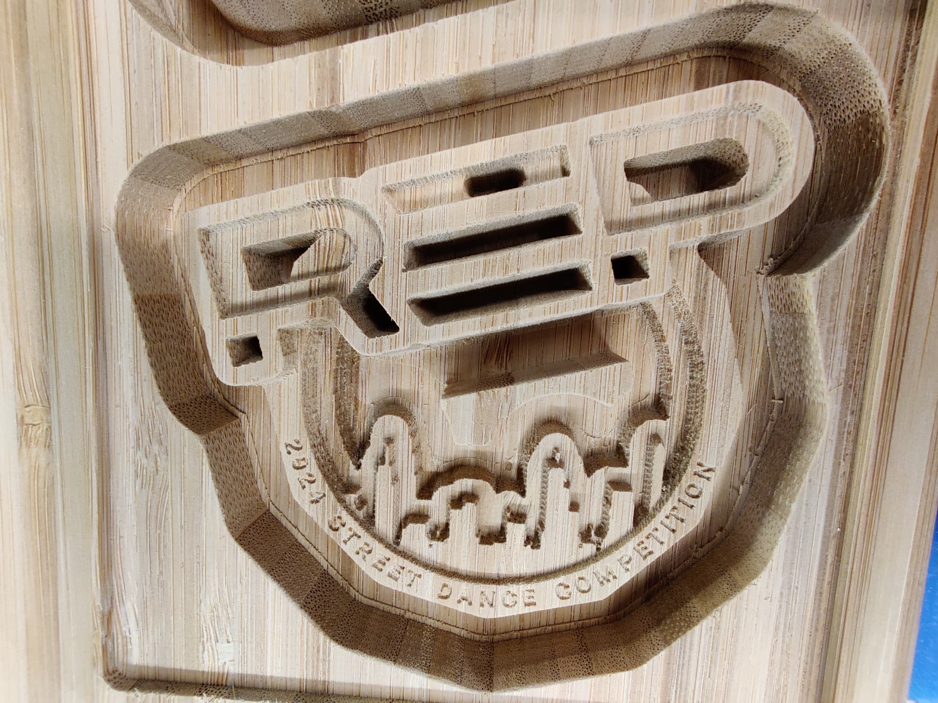
Doesn’t really help that I like to use 1/32" tapered ball mill - but I really like how it carves.
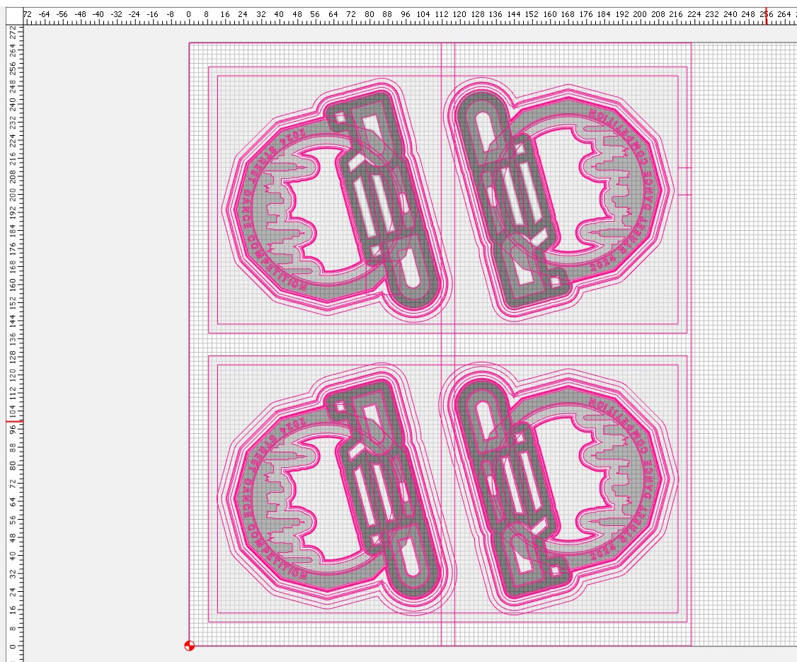
Essentially I’ve been re-working the base vector design with numerous offsets to utilize a combination of 3D milling & 2D contours/pockets that take into account the tapered ball nose at the different depth levels of the design. Trying to get to the point of using just 2D toolpaths to reduce cutting time to something I would consider reasonable per unit. Alternatively, I also decided to explore carving molds to make silicon casts for epoxy copies.
It’s an on-going process. I like what CC is able to do… Just not quite there to allow me to easily get to the next stage of the project.