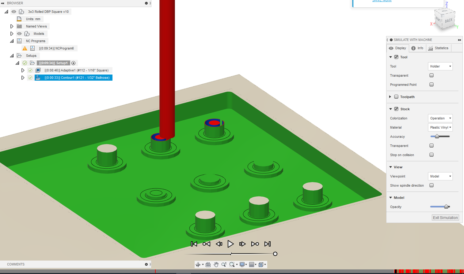
I was wondering if anyone knew how I could improve upon my toolpaths for milling acrylic with the Nomad 3. The first cut I made with this design took over 2 days of continuous running because I had used the same #121 ball nose end mills to mill every feature. I brought it down to 31 mins now that I am using the 112 for adaptive clearing and the 121 to contour the small inner circles, but the simulation states that my tool shaft collides with the stock at various points and I am not sure what to do to fix it. Alternatively, if anyone has any other thoughts on other ways I could cut my design with different toolpaths or tools I am open to suggestions! I have the basic endmill starter kit from Carbide, except the tip of the 122 broke so I need to replace it
Looking at the file and the tool:
The flutes are shorter than the depth they need to cut. So the tapered part of the shank is colliding with the tops of the small cylinders. Since the tool isn’t tapered in Fusion 360, it just assumes a straight transition rather than the tapered transition. So in real life the tapered shank would be wearing away the tops of those cylinders.
The feature is 0.118" deep and your tool only has 0.0625" of flute and then it tapers. So in this case you would need to get a tool that has at least 0.125" of flute length to avoid the shank rubbing the cylinder.
So I reworked my design and toolpaths, and got a successful simulation! However when I tried cutting my endmills broke. Any idea what could have caused this to happen? There was a smell of what seemed like acrylic burning
3x3 Rolled DBP Square (10 min).nc (505.5 KB)
Did you break the 1/16" of the 1/32" ?
The 1/32" toolpath simulation has lots of collisions,
I did not check if your tool is modeled correctly but first and foremost you should should check that ?
You used 4000mm/min (160ipm) in both toolpaths, at 15000RPM on those 2 flute endmills. Even though acrylic likes fast feedrates, 160ipm@15k (hence 0.005" chipload) is too taggressive especially on the 1/32th endmill
Also your depth per pass is quite aggressive too
1/16" is 1.5875mm is diameter, and you used a 4mm stepdown, so you are basically cutting at 250% the tool diameter, which is way too high especially for a fragile endmill like that
![]()
I would recommend: targeting a 0.0025" chipload, and cutting at 50% of the endmill diameter per pass
Which would translate to 75ipm / 1900mm/min here, and 0.8mm max stepdown for the 1/16", 0.4mm max stepdown for the 1/32". That’s after you take care of the tool collision issues.
The 1/16th kept breaking. I did not even get to try to cut with the 1/32 because of this. The tools seem to be modeled correctly. I also found a source on github that seemed to confirm my accuracy (GitHub - michaelgrilo/carbide3d-tool-library: Fusion 360 tool library for Carbide 3D cutters.) Should I make the same parameters for the 1/32 as the 1/16 as you recommended?
I am also not sure why there are collisions with the 2nd toolpath. The area that is said to be a problem with the 1/32 is going to be machined away already by the 1/16th in the adaptive clearing I do not know why it is adding extra stock to the height of those 6 cylinders in the simulation.
That’s a good question, because I just spent 20minutes trying to figure out what was wrong and I could not find the reason. The toolpath insists on leaving 6 of the 9 inner cylinders untouched,
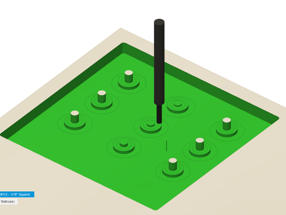
whereas it’s not supposed to and I could not find anything wrong in the model…
That’s one quirk to figure out, but then you will have to address the second issue which is that your 1/16" endmill length of cut is not enough to mill all the way down. By the way, I’m not sure why you are doing adaptive clearing with a 1/16" endmill here, when a 1/8" one could work and they usually come in 1/8" shafts so you would be in a better position to mill all the way down the 0.5" depth of the model ? It would also be faster and less likely to produce tool break.
And then do the finishing toolpath with your 1/32" endmill for the narrow slot in the cylinder.
I’ll try and play with the model some more.
Well don’t ask me why but just re-creating a fresh 3D adaptive toolpath from scratch gave the proper result.
Here’s the result of 3D adaptive clearing with a 1/8" endmill,
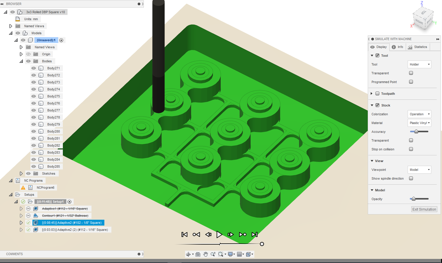
which you can then follow-up with another adaptive clearing with the 1/16" endmill (activating Rest machining),
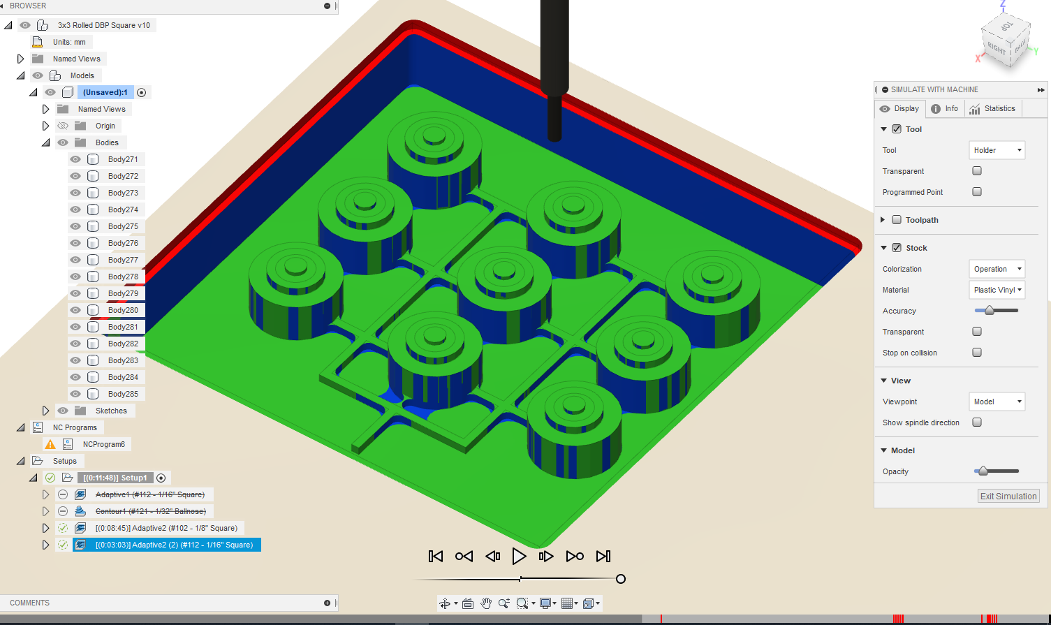
EXCEPT I did not address the problem of the 1/16" endmill limited reach/length of cut, so you would have to define a smaller boundary such that the tool does not hit the sides (red collisions area on the pic)
Anyhow, my advice would be to first try your feeds and speeds in a adaptive clearing of a simple pocket.
1/16": 15k RPM, 1900mm/min. And see how well it works, before doing the complex toolpaths for your model.
For the 1/32" I would dial down to 1000mm/min or so.
Thank you so much Julien I was able to make a much better cut! I’ve been playing around with the linking and passes for the 102 in this new design/workflow but keep getting these random small rapid collisions.
Ok now I have generated a completely collision-free toolpath but my machine started acting crazier than before. I’ve attached the file I used, as well as a video of how the machine had cut when I first started this post and a picture of the result from when I just tried my latest cut.
Hi @psen,
I’ll try and check the latest file later tonight. The pic is typical of chip melting which can be due to a mix of inadequate feeds and speeds (and DOC) and lack of chip clearing. I’ll check the feeds and speeds in the file, but regarding the chip clearing part there are two things you can do to make things better (regardess of this specific project):
- air blast aimed at the tip of the endmill. A number of Nomad users have modded their machine to add that, there are a few examples threads on the forum
- and more simply, procuring single-flute (and ideally O-flute) endmills. They work wonders in plastics, and a large part of why they work well is because they provide optimal chip evacuation capability with their single large flute. Therefore chips have less chances of staying in the cut, being packed against each other and being recut, and melting.
This is my latest attempt, there was not a single collision, yet my machine acted just as irregular as before. Do you think this may be a hardware problem? This time it actually removed some random chunk of stock from the bottom that I had been saving as a floor for my model.
Do you have a video of that erratic behavior the machine is having ? The toolpaths in the latest project look ok. The fact that you mention it removed some “random chunk of stock from the bottom” could indicate a defective cabling to the Z stepper motor. If the machines movement is jerky, this might be it, but a video would be good to confirm
This is a link to a video of it before the erratic movement. It did move back and forth a lot, but I stopped the machine and recording right when I saw something going horribly wrong.
This topic was automatically closed 30 days after the last reply. New replies are no longer allowed.