For completeness, I re-created the shape in CC and generated the CAM there, in case I had a Fusion360 parameter wrong somewhere.
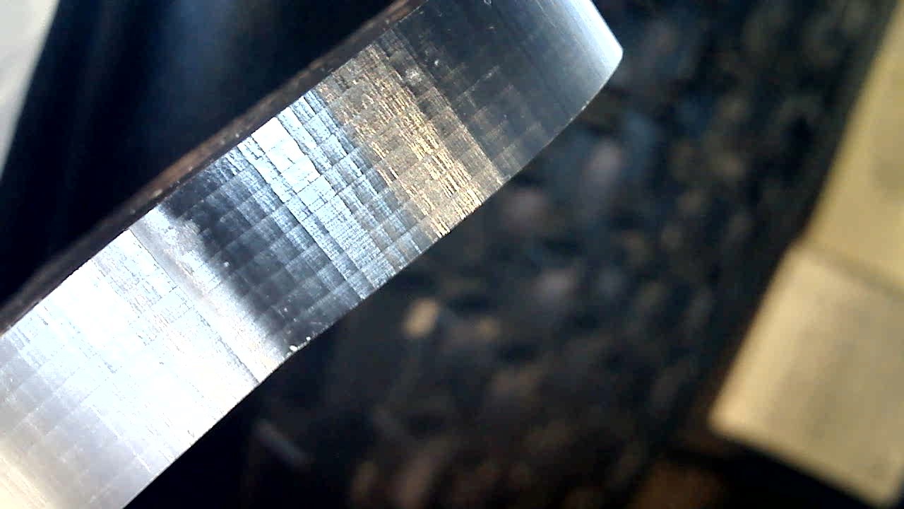
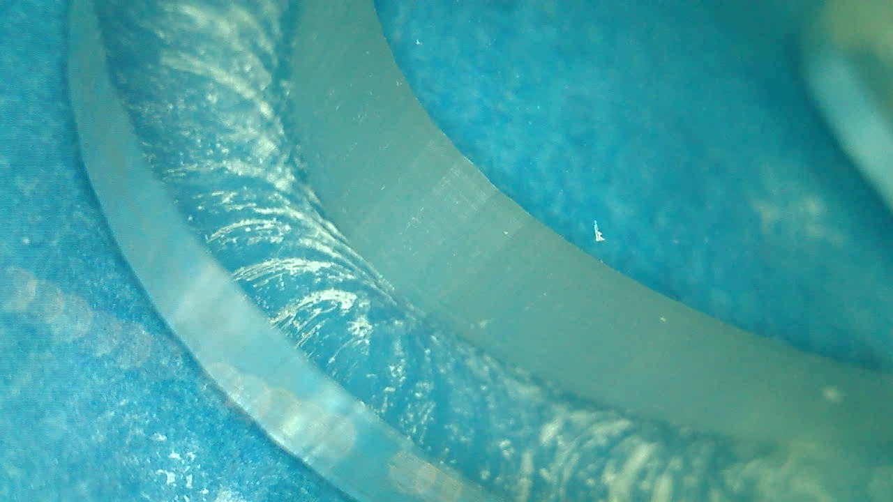
The generated G-code uses small segments in curves instead of arcs (as expected when using CC), and since this was a simple contour toolpath there is no finishing pass at full depth anymore. With the right lighting, the marks of the horizontal passes are clearly visible (I have to re-tram my spindle slightly, but that’s for another day), BUT the vertical marks are all perfectly aligned across cut layers:
if this was indeed vibration, would they be random from one layer to the next ? It could just be the last layer leaving cutter marks at full depth, but it looks too regular to be that?
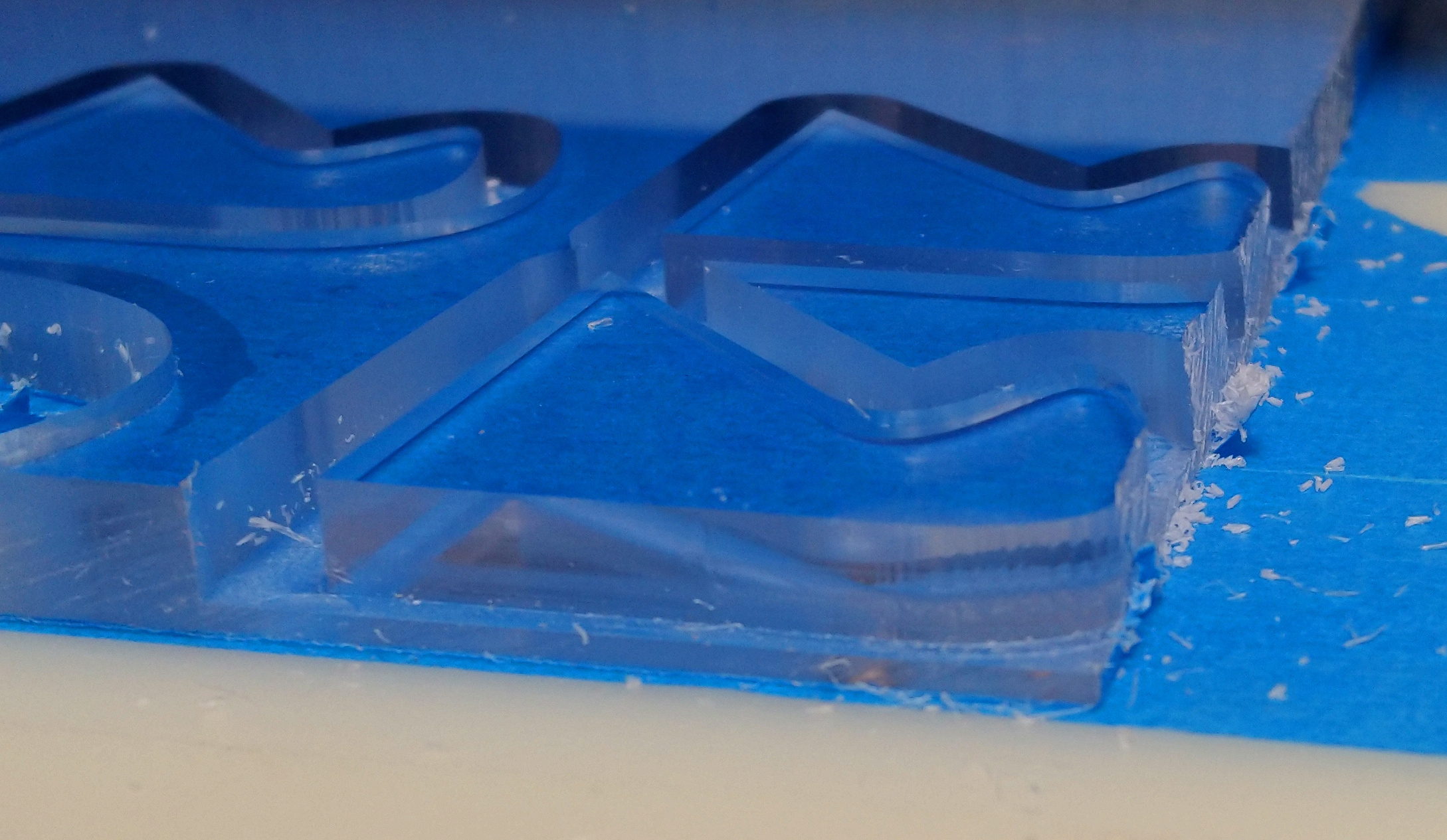
I have tried other (cast) acrylic cuts and the marks are there too, but it’s harder to see in opaque acrylic, so the rest of my tests were done with transparent acrylic.
I’m happy to see a close-up of anyone else’s unfinished walls along curves, as a comparison point.
@Julien i dont have much if any cast left but send me the file dude and i will try this if i can, I was out in the workshop today tinkering so the machine is in tip top shape, she had a shower too lol - well a good clean at least, bob on tram square etc (yes i know what a lovely Sunday afternoon in the shop).
i suppose i need to make sure i got same cutter as you, to make it as like for like as we can ?
I don’t think the piece matters a lot as long as it has one edge aligned with X, one edge aligned with Y, and one curve somewhere. The tool is an O-flute 1/4" (Amana 51404) but I also tried 1/8", and 3-flute (#201) for finishing, and it does not seem to have any significant impact.
Here’s my messy test file in Fusion360 so that you have the dimensions and latest cut params (I made an array of identical parts to make multiple tests)
I have been silent on this, as I use a Nomad, not a Shapoko, but you might want to see: No G2/G3 ARC Movements?
The C3D post for Inventor does not produce G2/G3 (unless it has been updated since last august… I just tried it), and I see the same effect on my Nomad.
If I adjust the tolerance the effect is reduced, but, obviously, the file size increases.
I don’t know if CC does it the same way, of if it used G2 and G3, but the $12 parameter in GRBL sets the interpolation precision. Take a look at the g-code file you are running to see if there are G2/G3 commands. If so, this can handle it. If not, tighten the tolerance on the operation AND when you post (there is a configuration setting in the post popup window for this in Inventor and, I think, Fusion)
Or, replace the operations in the g-code file by hand with G2 (or G3) as appropriate. This will take a little work, but might be worth it to you.
@enl_public, thanks for the pointer, but that’s exactly why I’m scratching my head: because except the very last test I did in CC (which indeed generates linear segments, no G2/G3 arcs), the rest of them are from Fusion360 and they do use G2/G3 in the generated code. And when I tried to decrease tolerance (following @Vince.Fab’s example of 0.0001"), it did not change much.
There is always the possibility that I did a mistake in somewhere in the settings, of course.
@fenrus: I have, but I can’t see how discrete steps of 0.025mm (1/40th of a mm) can end-up producing those segmented curves when I estimate the distance between successive vertical marks to be around 0.75mm (eyeballed)
Also (yes, I’m going all over the place now) I tried a finishing pass with
a downcut single flute
leaving 2mm stock at the bottom of the cut in case this is all something to do with the small piece vibrating after the roughing pass cut it out of the stock and it’s only held by the tape & glue
I got beautiful straight walls (so I made a mental note to try downcut for finishing when this is all sorted out)
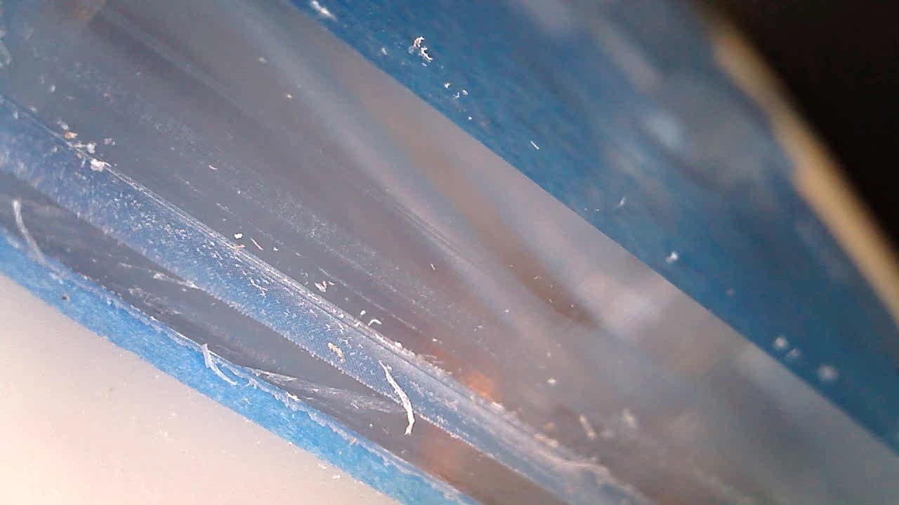
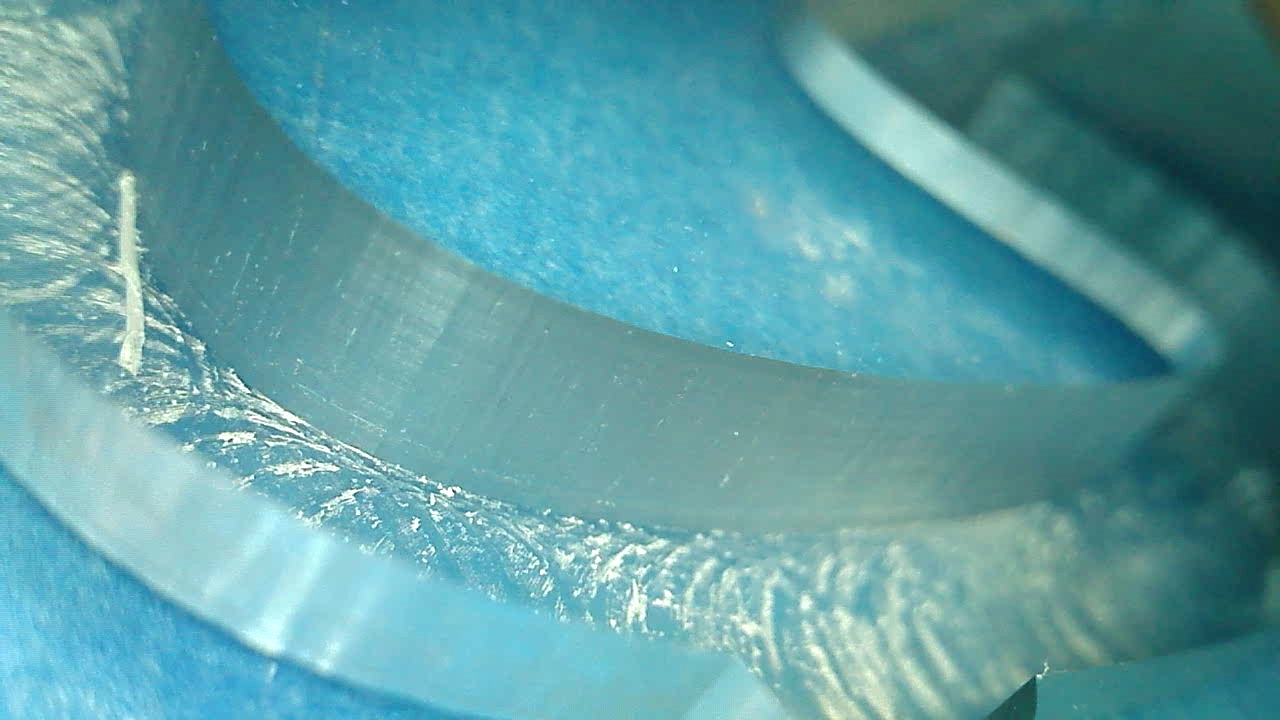
Here’s another shot, in the straight part you can actually see the inside through the wall, the picture does not do it justice but that’s the finish I’m looking for…all around the part
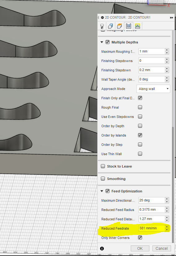
@Julien hmm interesting - i must be honest when i saw that i was like ah ha! i know what it is, i thought you had feed optimisation on (slows down feed rate on corners by a factor you set) but looking at the file you sent, we can say the man form Wales say “nope feed optimisation is off”! going to sort kids out then pop up to workshop later to try this if i have enough stock!
ok so half way through typing this i wonder if you could do the inverse of this and instead of saying slow down with feed optimisation, increase it Julien to see if it still slows down?
I’ve cut quite a few patterned test sheets of black .5" cast acrylic. A honeycomb pattern for instance, every hexagon having a different cam adjustment. I have yet to achieve a reliable and acceptable off the machine finish with my Shapeoko for my purposes. Each of the 6 sides will have a slightly different finish. I get the same segmented finish on curves, which by itself, is generally acceptable to me. But being I have to post process every piece, requires addional hand machining. I’ve played extensively with resolution in Fusion cam, but nothing outside of that. For the most part, full DOC finish passes have proven difficult because a sufficient WOC seems to load the machine a bit too much.
For profile cuts, I was modeling addional geometry and then clearing before finish profile cut. But I’ve given this up for a profile cut with finish passes and a lead out. I contract out most of my work, sometimes with my own cam, and the results are not comparable. The finish from an industrial machine with a .375"+ cutter is rather substantial upgrade. The same or better than that produced by a quality router table, shaper, or jointer. I am also no where near proficient at these things, so take my observations for what they are. I’ve read comments on here about being able to achieve the same finish with Shapeoko, as say with a handheld router. While I believe this is likely possible, the effort per project hasn’t yet proven equitable to me.
I am very interested in thread, and look forward to hearing what others have encountered and suggest.
Reduce it to 0.002 (GRBL default by the setting guide)
The linear interpolation can be considered as a sag calculation (the sagitta formula is s=r-\sqrt{r^2-l^2}, where r is the arc radius, l is the length of the half-chord, and s is the sagitta).
Example: if the radius is 25mm and the sag is 0.02mm, the flats are 2mm long (l=1.0).
r=25, sag=0.005, then the flats are 1mm (l=0.5mm).
r=25mm, sag=0.00125, the flats are 0.5mm long.
At r=12.5, the 0.01mm sag gives flats 1mm long (l=0.5mm)
I’ll be very interested to see if the machine starts to slow down, jerk & stutter with this value reduced as the CPU in the controller is a little lacking in grunt.
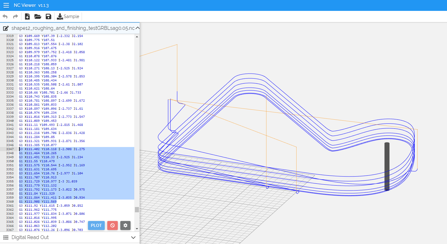
@enl_public: very interesting bit of info, thank you. I had my hopes up! but…I adjusted $12 to 0.002, reran the cut (video for @LiamN: no visible/audible stuttering going on)
and the corner is still segmented, with the same segment length as before…
Is there anyhing that would make GRBL not taking my $12 into account ? To be sure, I power cycled the controller after adjusting $12.
And now of course I have to do the opposite test, putting a very large value in $12 to check if there’s any effect (i.e. that it IS actually taken into account)
it’s a succession of very small G1 linear moves and very short G3 arc moves. I guess this is why $12 is irrelevant? (i.e. the arc length is so small that it does not even get to break it down into multiple segments?)