As a newbie to the CNC router community , I soon learned what happens when the router power cable gets caught on a high profile item. I decided to implement an extra drag chain assembley on the right Y axis, like the Shapeoko Pro.
To do this is fairly simple and requires the use of a 3D printer to manufacture the support brackets, some high strength double sided tape, and if you feel brave, then a drill and tap set.
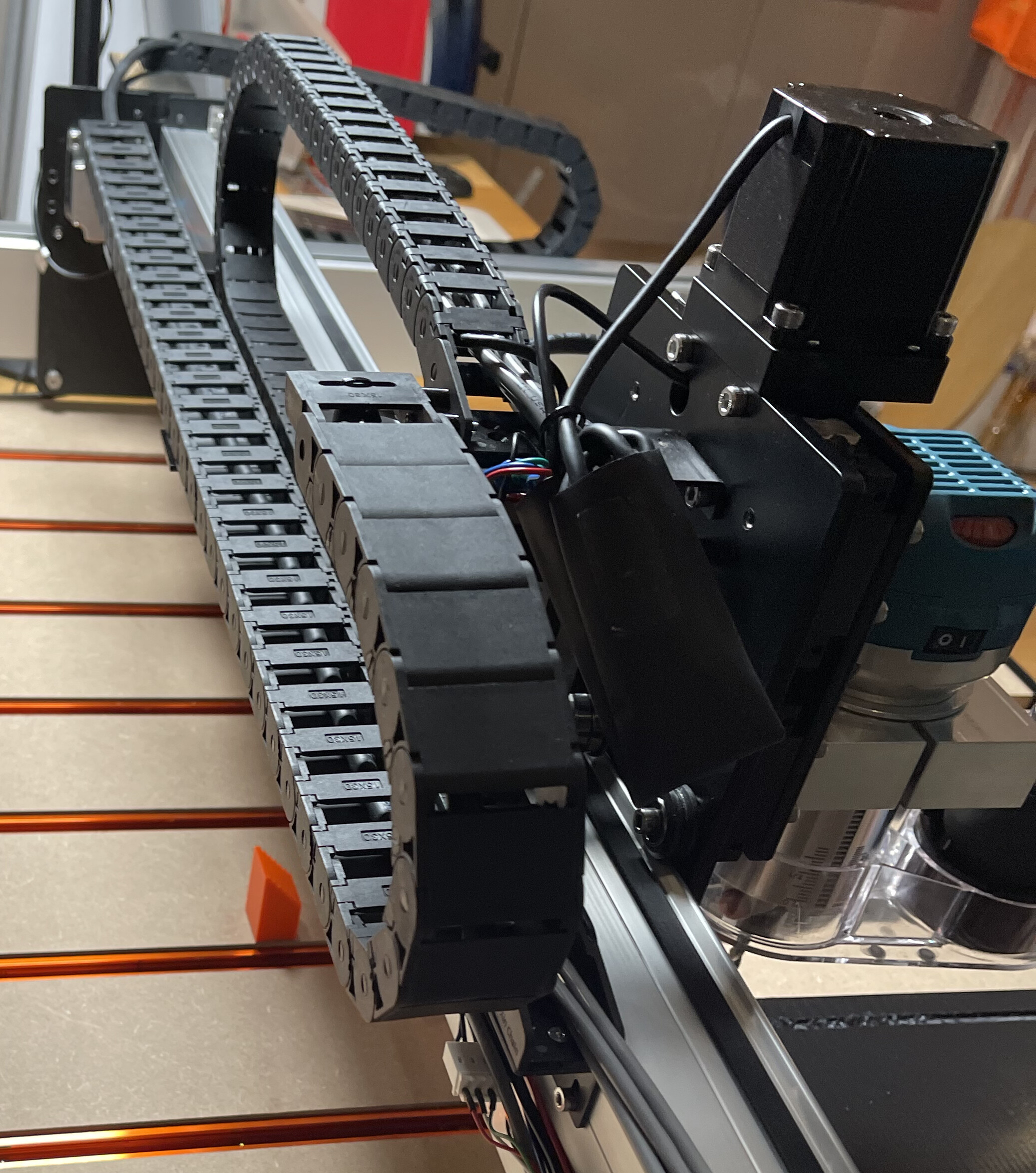
And of course, drag chain which I got off of Amazon. I chose a larger size than is installed by Carbide3D as I wanted room for a router power cable and maybe other cables such as a long length shielded USB or USB-C cable to deliver signals to accessories via the Z axis.
Here goes…
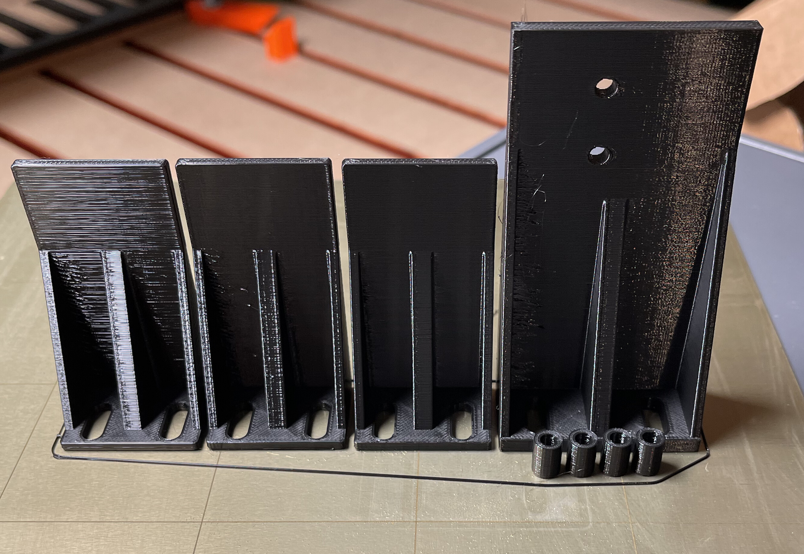
I designed and 3D printed the brackets on my Prusa using PETG. I had a few failures in terms of strength and brittleness and probably, I could have used PLA. Ive added structural support in terms of the spars but I’m not a designer of these things so I am sure someone else will offer a better design.
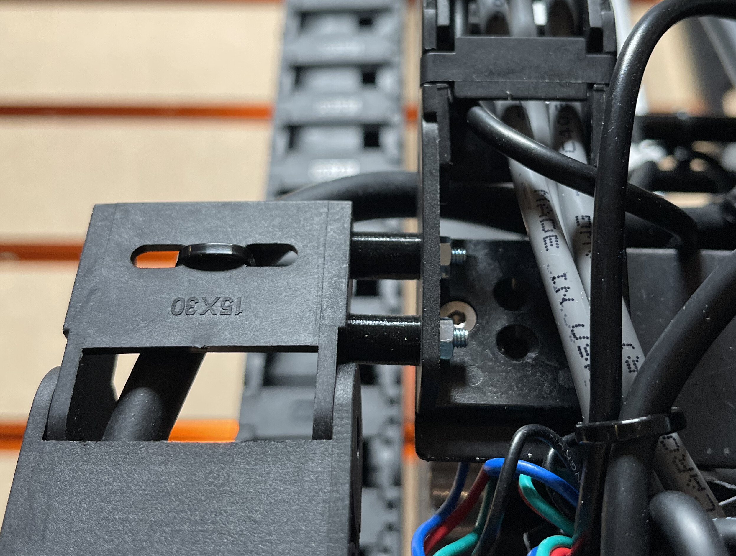
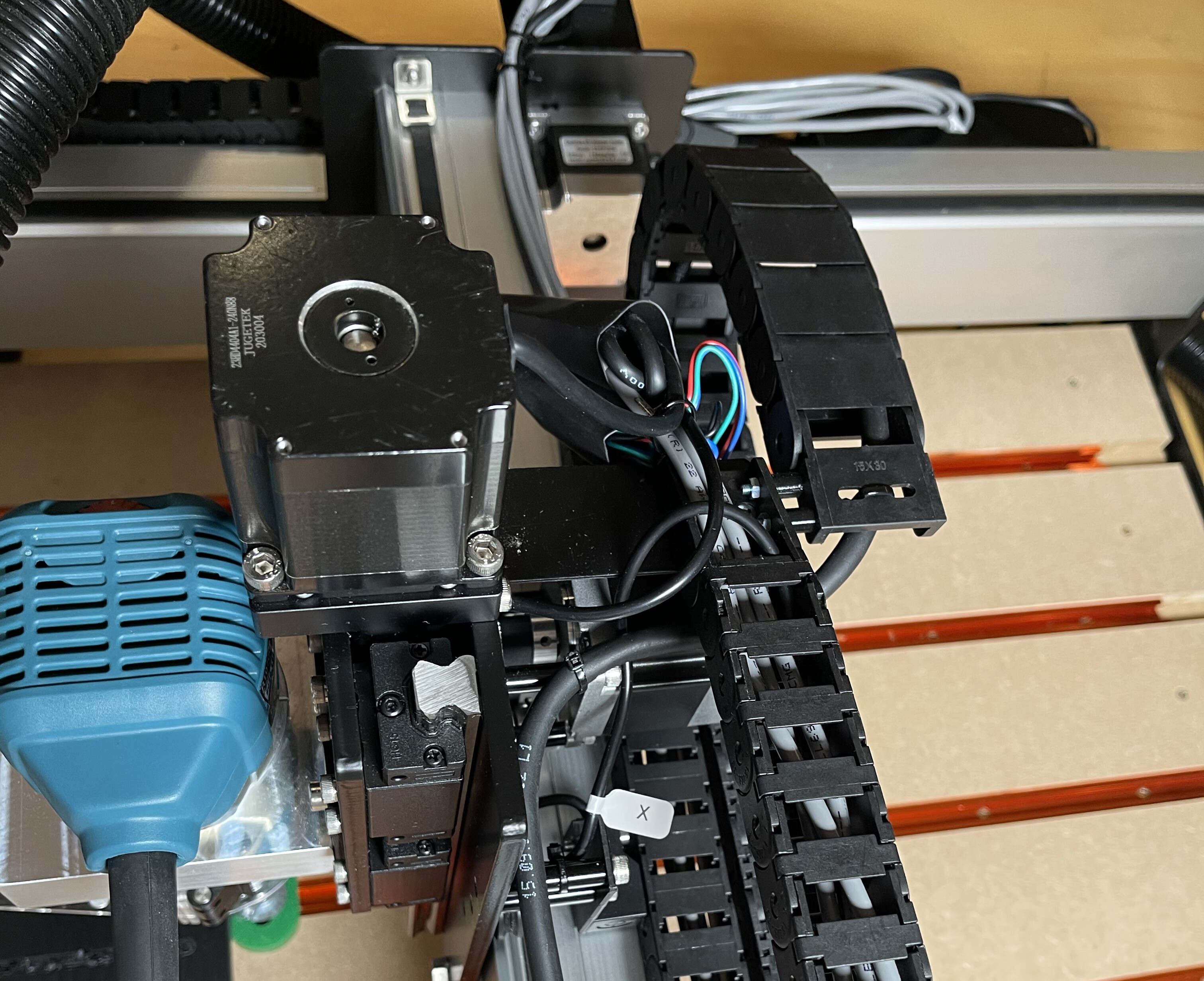
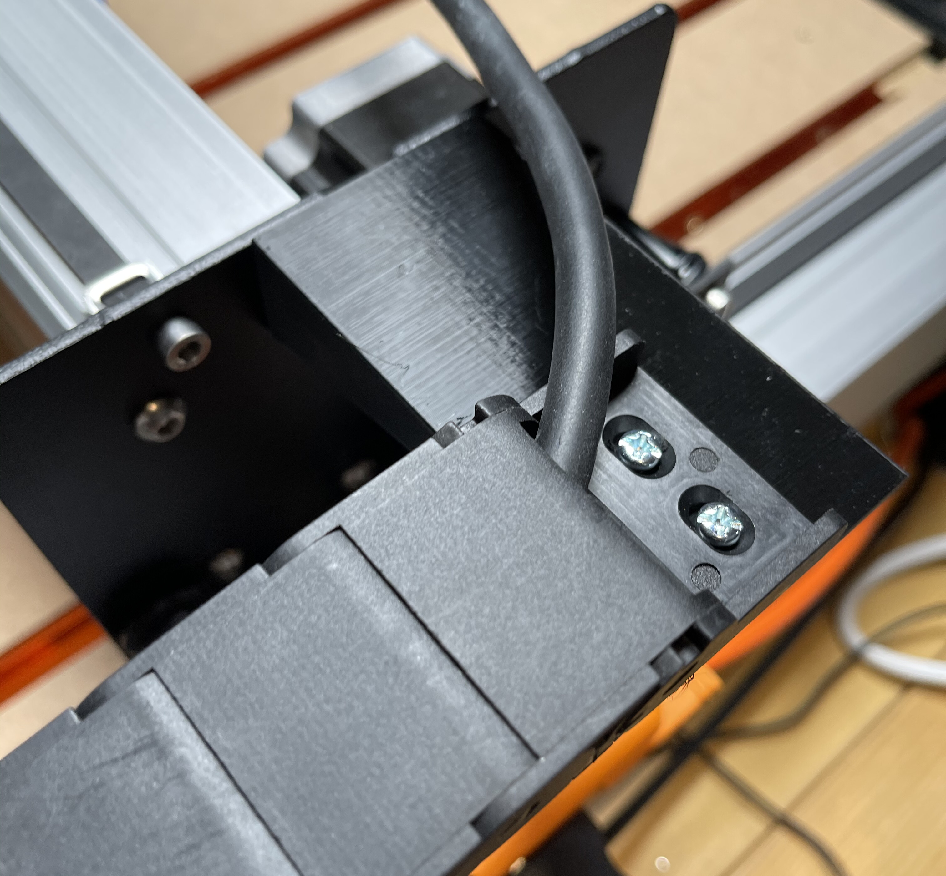
I started by adding the x axis chain by drilling two small holes in the existing x axis chain end piece mount and used some nuts and bolts and stand off pillars to avoid fouling and friction.
I had to remove the plug from the router to enable me to thread through the power cable. Do it before you mount the x axis chain otherwise you’ll end up trying to invent threading procedures. No plug and gravity are the easiest way. For me !!
Remove the existing two outer x axis metal chain support brackets and replace with the printed parts. The hole spacing is the same and the provided bolts are long enough.This will support your new chain.
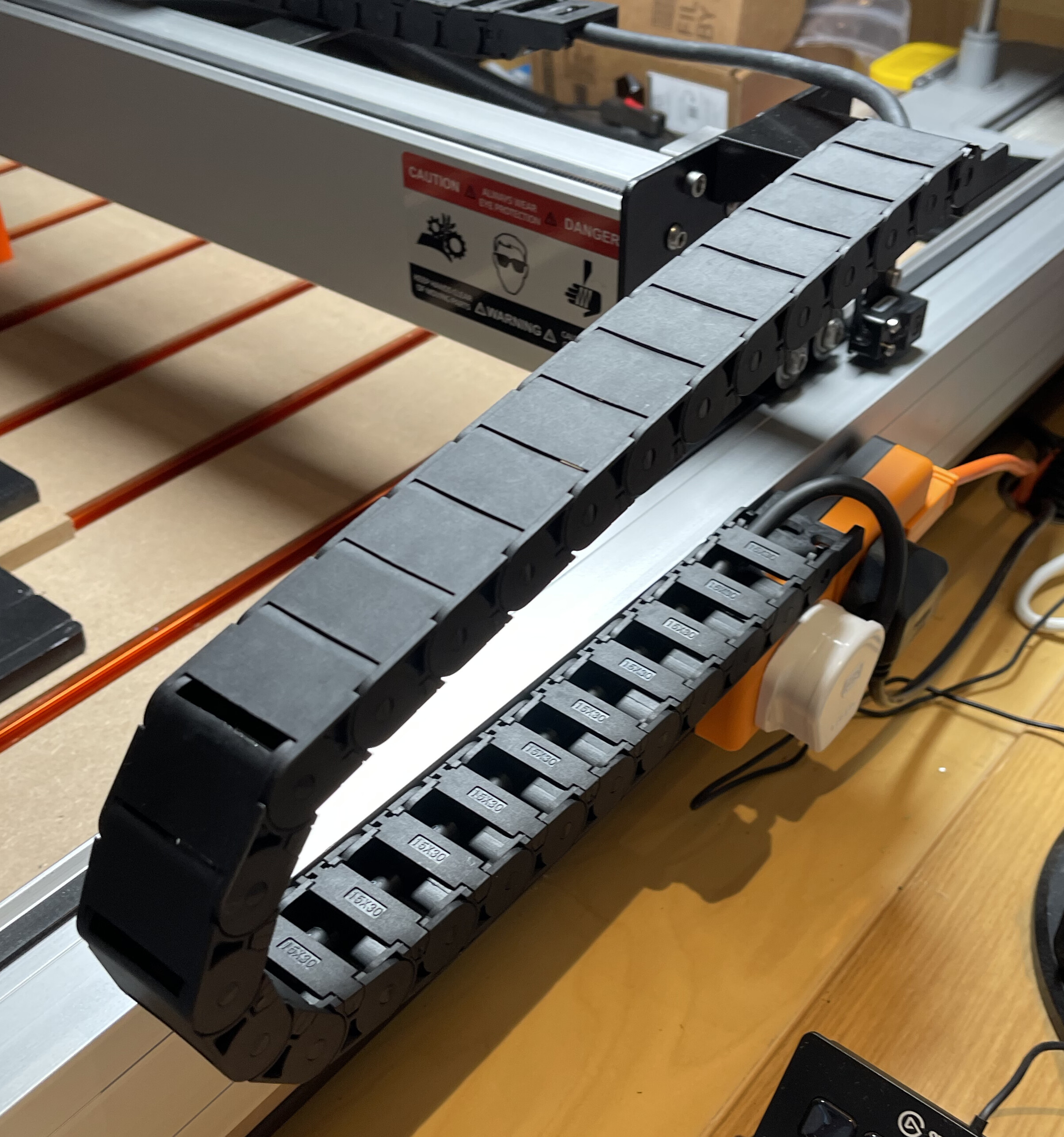
Ensure to move the carriage to the left hand side when setting the chain to be curled appropriately for that limits. Cut a couple of lengths of the strong double sided tape and place them on the top of your new brackets to stick the new drag chain to it.
On the outer side of the right Y axis, place the larger chain support bracket in place and mark with a pen, two bold holes through the bracket slots. You can either drill 4mm holes in the aluminium frame and tap, or use more double sided tape to hold the larger bracket in place.
Thread the rest of the router power cable through the y axis drag chain.
In my case, I velcro’d a UK power outlet driven by my BitRunner alternative to the Y axis extrusion and I rested and double sided taped the drag chain to the top of the outlet.
Thats it. I no longer have floating cables over the work piece and I can add accessories to the Z axis, such as a laser cutter, laser pointer etc.
With the new capacity to route cables to the Z axis without snagging concerns - I’ll do a couple of things.
A) cut the power cable to the router and replace the cut with some IEC power connectors. Male plug end on the router and female flag end from the drag chain. This makes it easy to remove the router from the collar and put in some other device.
B) add screened power cables for other low voltage power like 5v or 12v or 24v to power lasers etc.
C) add a usb cable to attach a head camera.
D) attach led strip lighting under the gantry. This cable will exit the y axis drag chain only.
E) optional add a usb cable for the gantry to attach a rear mounted forward facing drill camera.
Ideas are endless.
I hope Carbide3D will look at offering a proper metal bracket retrofit upgrade to provide new drag chains.
Fingers crossed