I had a very successful run of chess pieces as more or less a prototype of “could I do this on the Shapeoko”? I was beyond thrilled and am going to try an improved run with the following goals:
better two-sided flipping
putting all pieces per color into one piece of stock to optimize cutting vs. tool changes
this topic: improving yield (reducing defects)
By far my biggest hurdle was transitioning from roughing to finishing on the thin ring-like features on the pieces. It’s hard to find good examples of this as I scrapped them and of course didn’t use my worst results for my build or glamour shots Here’s an example, though (bigger pic in case the upload gets reduced):
My key strategy after observing where and why these chips occurred was this:
after roughing, my main finishing pass is a parallel path
if you imagine starting at the base and doing very small step sizes toward the head, the tool will come to the apex of those rings, at which point there is very little material behind the ring since you’ve machined it away already
on the approach to the apex and subsequent steps toward the back side of the ring, passes can rip out chunks because there’s no “meat” to support the stuff you’ve already finished
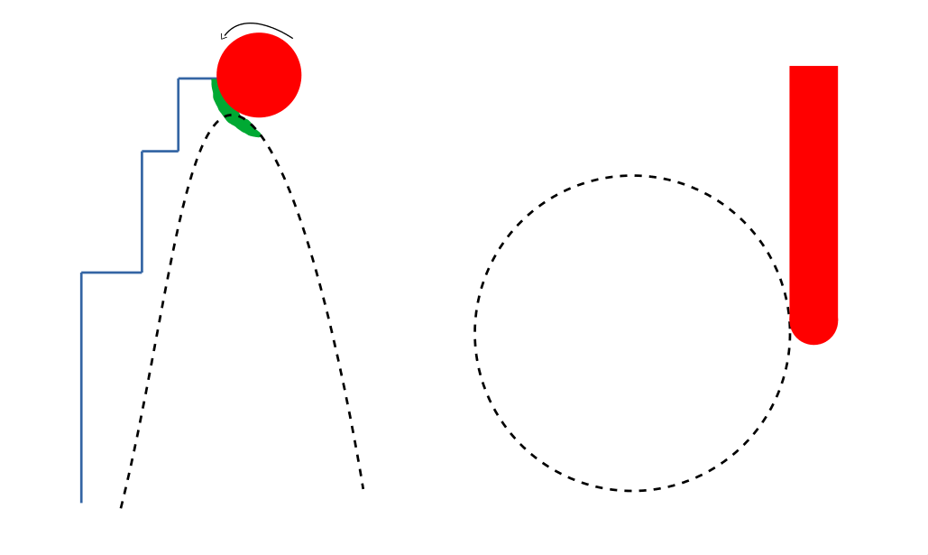
on the left you’re seeing that ring from the top (pawn head to the left, base to the right); on the right is a view from the bottom
the remaining stock after roughing is shown in blue, final part in dotted black, and red is the tool (top down view on left of my 1/8in ball end mill)
the parallel pass has come down to the bottom of the cut (i.e. the center “parting line” of the piece since I’m using 2-sided machining)
the bit advances toward the head by it’s step size, and as it takes the next “bite,” it’s removing the green (which includes stock and some chunk of the ring meant to stay)
my observation has been that since this ring is so delicate, as it takes this “bite” (particularly toward the center line where a) the axial advancement “jolts” forward and b) the flutes are perpendicular to the part shape), it rips out some of the finished ring because there’s no “meat” to support it as it’s already been finished and is by nature so thin
To combat this, I started using a scalloped toolpath machining from inside → out. If you do this within a sketched box in Fusion360, you essentially machine from “highest/furthest from part axis” to “lowest/closest to part center.” In this way, you’re constantly machining stock toward the direction of “more meat.” You finish the most delicate peaks of the mountain when there’s till meat “downhill” on both sides.
With all this backstory, I’m wondering if there are folks doing intricate/small work like this (thinking of 2.5d carvers for example?) who might have additional strategies for me? In particular, I’m wondering about:
should be using a down cut spiral to further, as the stress on the next-to-be-cut chips is toward the part vs. ripping up/away? I can find plenty of info about clean lines on signs and bottoms of contours between up/down cut, but not on things like carving
I have flip flopped between feed rates. I’ve tried faster passes, as I’ve felt like more time spent by the bit on each area increase the chances that any given rotation will chip out. I’ve tried slower passes thinking I should baby these areas with tiny bites
I also don’t have a sense for how much axial/radial stock to leave in my adaptive pass, wondering if too little hurts by not leaving enough “meat” to support the delicate areas, but too much might be hurting because finishing is ripping away bigger chunks, which might in turn be more “rooted” into the surrounding wood and chipping
If you made it through all of that, thanks for coming along for the ride and I appreciate any input!
Maybe make that area a little thicker so it is not such a delicate point. No one will get a caliper out and measure it. The staunton set is open to interpation. Plus if it is so delicate the pieces may get broken during handling. FYI. I made a modern set and Edward Ford pm’d me and asked for the files. I had made the chess men on the table saw and not on the Shapeoko.
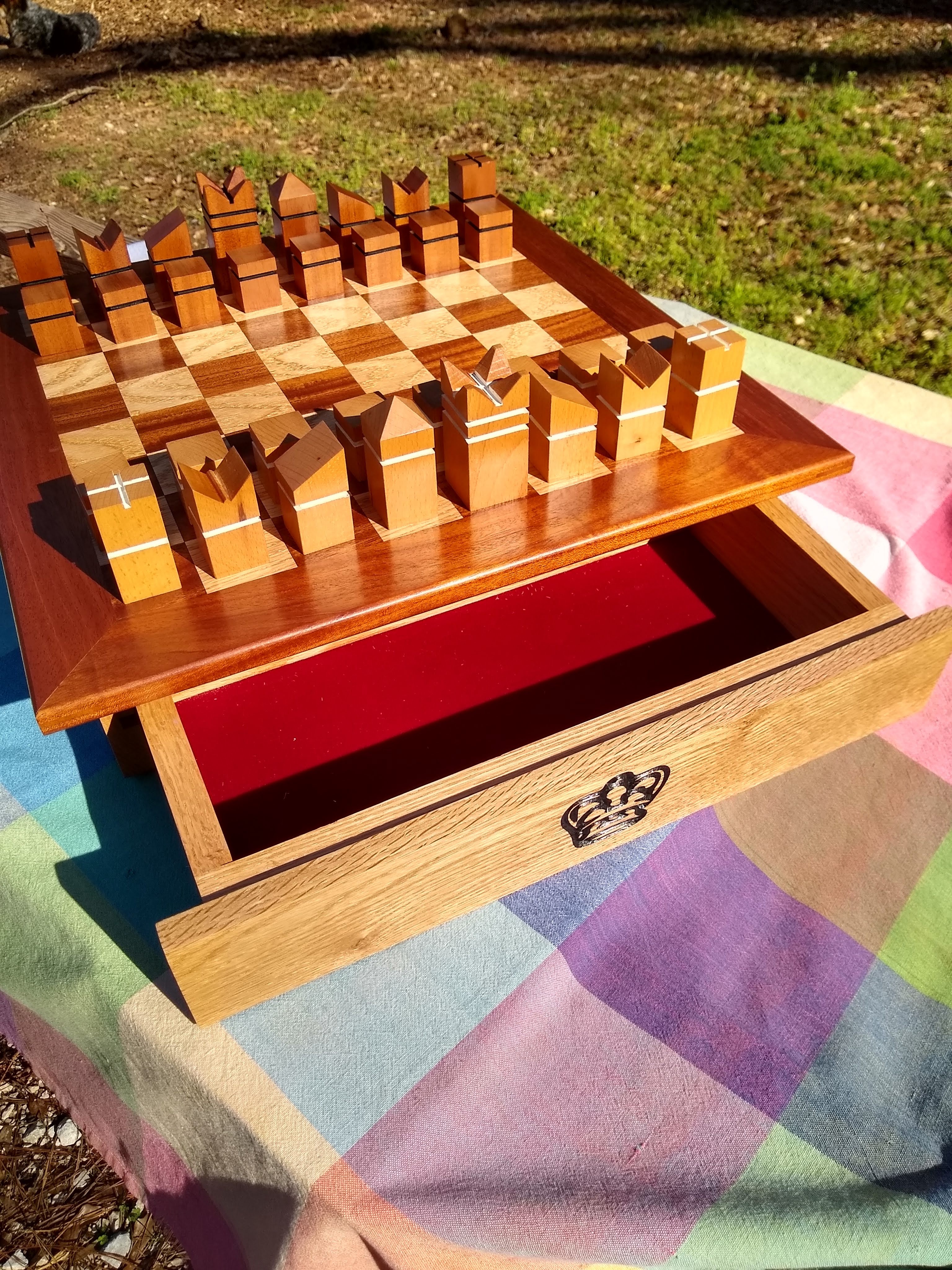
Gorgeous! I like that and reminds me of others I’ve seen done on the table saw. I want to try that at some point as well. Did you also make the board? I made a couple boards and want to get into drawers, though I haven’t tackled that yet!
Honestly, they’re really not delicate once cut, though that strategy is also on my list. I plan to tweak here and there within my artistic license to stay true to the form while not shooting myself in the foot on some of the trickier areas. I’ve even noticed that in some well-renowned reproductions the edges are more radiused than what I did, so I think I have room to ease up.
That said, I don’t think increasing thickness is really the problem. Two illustrations of why not:
run a 2d contour to make a square out of any thickness of stock you want. You’ll destroy two of the corners like nothing with an end mill.
chisel or plane any stock thickness you want and you can blow out the backside of a corner going the wrong way or cross grain.
In either of these cases, those corners would otherwise hold up to all kinds of abuse, and we’d never think of an e.g. 3/4 thick piece of stock as “delicate.” I think this is about how one gets to that final shape, not the shape itself.
Continuing with the analogy, in the “regular woodworking” world one could propose all sorts of strategies: sharper tools, knife walls, masking tape on the exit side of a saw cut, learning to read grain direction, using the right blade for rip vs. cross… that’s the sort of stuff I’m looking for here, but for the CNC world.
Leave a roughing clearance, take a finishing pass.
A slight variation:
Leave a roughing clearance, spray w/ a hardening fixative/lacquer, take a finishing pass
Here, it’s a 3D operation?
Leave a larger clearance, use a progression of smaller tools.
Turning something like this on a lathe one would look at the wood and its grain and strategize where to place the delicate feature, and when turning it, work up to it slowly, cutting oversize, gradually sneaking up to the final size.
For the 3D flip version of this, orient the stock for the initial operations so that one leaves the cutting of the delicate end grain until the final operation w/ the smallest tool when removing the thinnest chips.
I did make the board. I used Mahogany and Oak. I thicknessed all the material to 1/4 inch. Then I cut it into 2 inch strips. Then I glued alternating material together. I then trimmed one edge and cut 2 inch strips making alternating pattern strips. Then I glued the strips together on a plywood base. I have a drum sander and sanded smooth. You need a very sharp table saw blade to avoid splintering. I used Mahogany border with 45 degree miters. I reinforced the corners with splines. The base is just two oak boards with a slot cut in them with a piece of 1/2 inch by 1/4 inch to make a drawer runner. There is a center board to stop the drawers with magnets in them to get a positive drawer stop and keep them from coming out when moving. The base makes an H shape and I used Kreg pocket screws to attach the base to the board. The drawers were made with box joints and a drawer front with the king image cut on the Shapeoko. I just cut 5/16 slots to fit into the drawer runners on the side pieces. The finish was two coats of dewaxed shellac and 6 coats of wipe on Minwax satin polyurethane oil based wiped on, sanded between coats with 400 grit. The drawers are usually made with a captured bottom. I instead rabbet the bottom 1/2 inch wide by 1/4 inch deep and make a plywood bottom that is screwed on. This gives me an extra 1/4 inch drawer depth over captured bottom. I predrill the bottom and countersink the flat head screws. This is to put the red velvet on the plywood base and trim it and then screwed on to the drawer bottom. It is very hard to get the psa velvet to be placed perfectly and this way the velvet is 1/2 inch under the drawer bottom and you get a perfect result. I have seen many antique boxes that the velvet is worn and would be very hard to replace. For my design you unscrew the base and put new velvet in and you have perfect results. As you can tell I have made a few woodworking items before.
Thanks for the input. That’s my general strategy. I’m adaptive clearing with a 0.25in, scallop + parallel with a 0.125in ball, and cleaning out where the flanges meet the body and areas in between rings with a 0.5mm tapered ball. The brunt of the finishing is with the 0.125in, though, and that’s usually where I get chipping. There’s some that can happen in the “webbing” that gets left in between double rings like the bishop, queen, and king.
Funny re. “fixative.” I was thinking of using shellac or something, though I also don’t want it to soak too deeply to muck with my final finish. I used Odie’s Oil, but if I switched to a lacquer, I could use that for hardening, then final finishing as well.
The end grain is axial to the piece, which indeed makes it tricky. You expose it on any transition in diameter, so pretty much impossible to avoid.
Maybe for simplest of my questions: is a downcut or upcut better given my symptom, or doesn’t it matter? And slightly more complex: how much is a “roughing clearance” and at what point is it too much vs. too little and how would one know?
Downcut, but downcut ball-nosed endmills are a specialty/expensive item.
Roughing clearance should be larger than:
any likely deviation in the machine for a given operation — so when plunging initially, larger than any deflection one will likely see
greater than any chipping one will likely see given the tool being used for a given cut
equal to or smaller than what you would expect to cut with the succeeding operation(s)
It’s a balancing act, and the first consideration is how many passes w/ how many tools one wants to make use of — start w/ the smallest tool and set its roughing clearance equal to the desired chipload for that endmill and work back from there.
 Here’s an example, though (bigger pic in case the upload gets reduced):
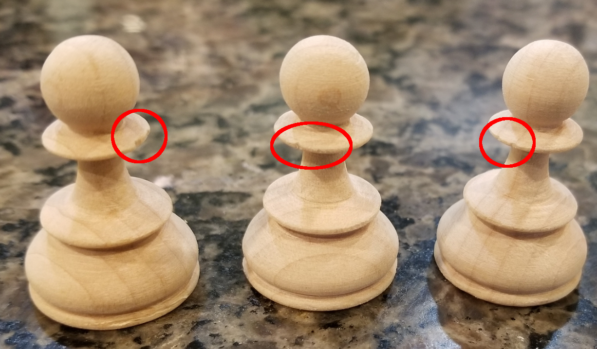