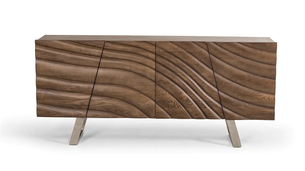
Would like to recreate this cabinet face using Carbide Create Pro if possible. The wave crests and troughs will flow into each door from the adjacent door and also flow off of the edges. Have created the 2D layout with Carbide Create Pro without any problem. Don’t know how to create a tool path for the layout that will square off on the edges. I can not machine the complete face and cut it into individual doors due to the envelope size of my CNC. It is large enough for the doors to be machined individually. I don’t know if it is possible in Carbide Create Pro to divide a surface into smaller sections before creating the tool path.
I have been researching how to create an STL file with FreeCad that could then be imported to Carbide Create Pro, although that would have a long learning process. This is a one off. Just making a piece of furniture for the daughter. Any ideas?
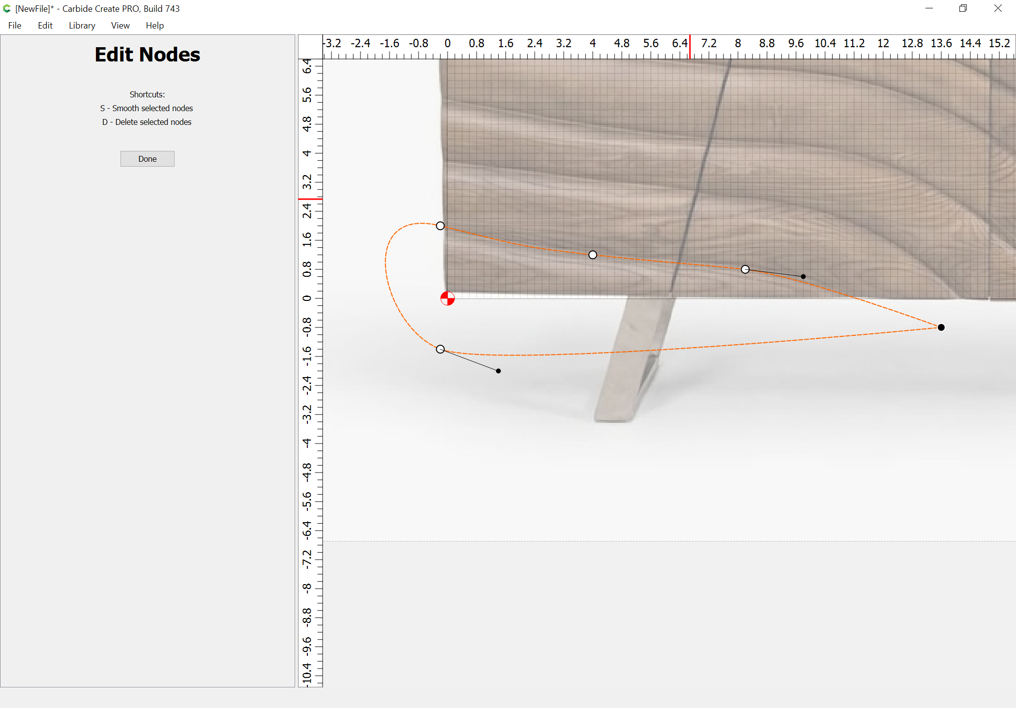
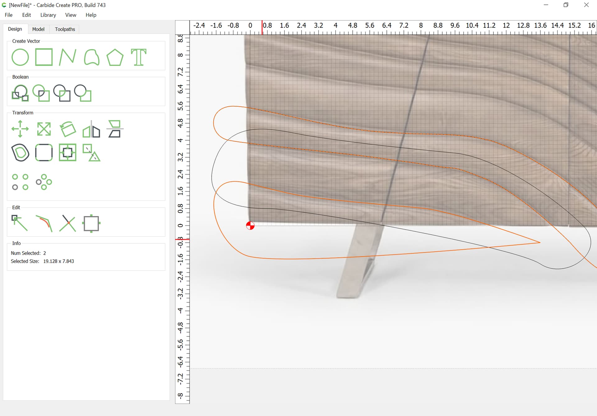
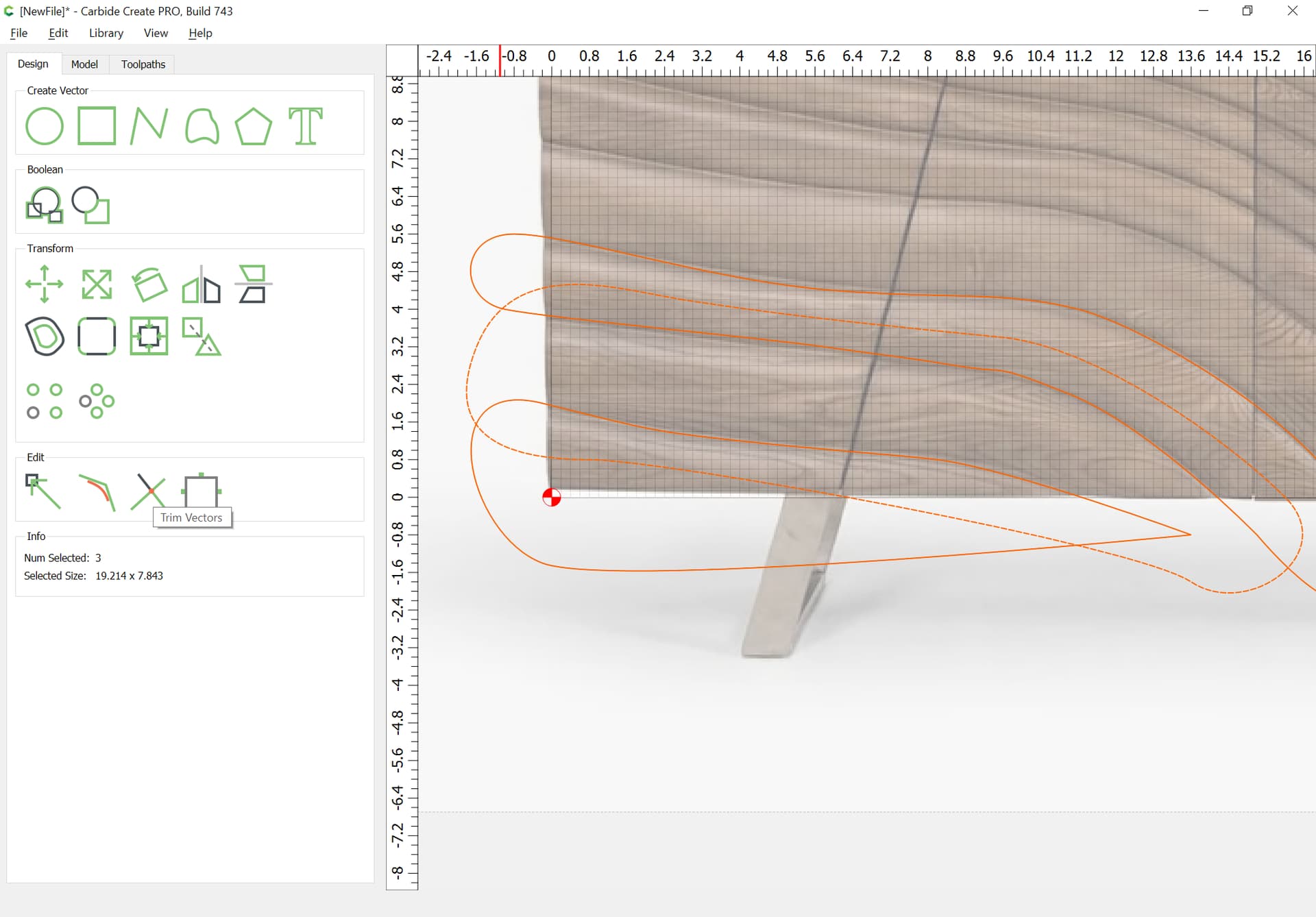
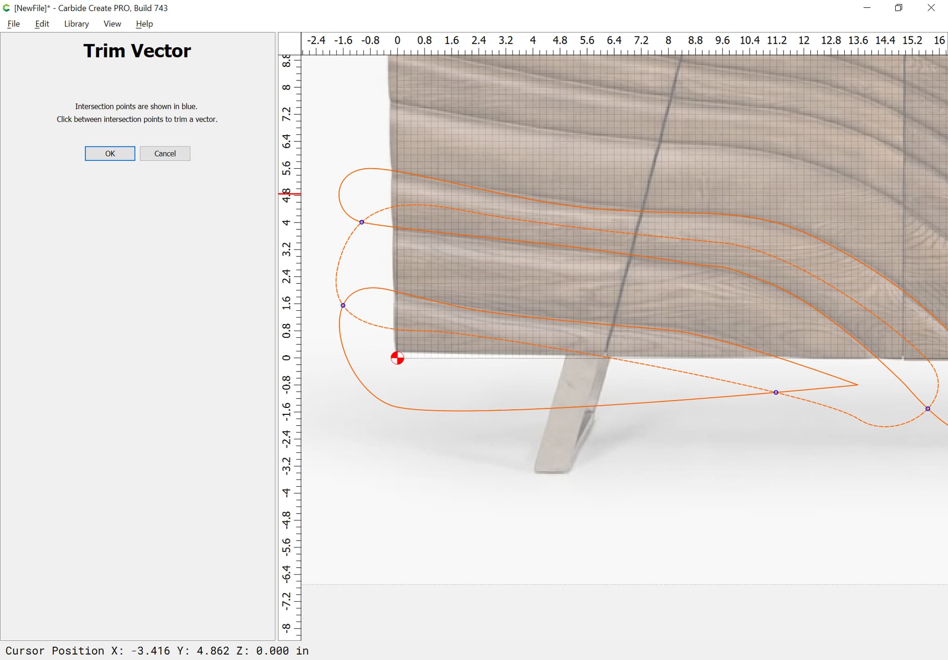
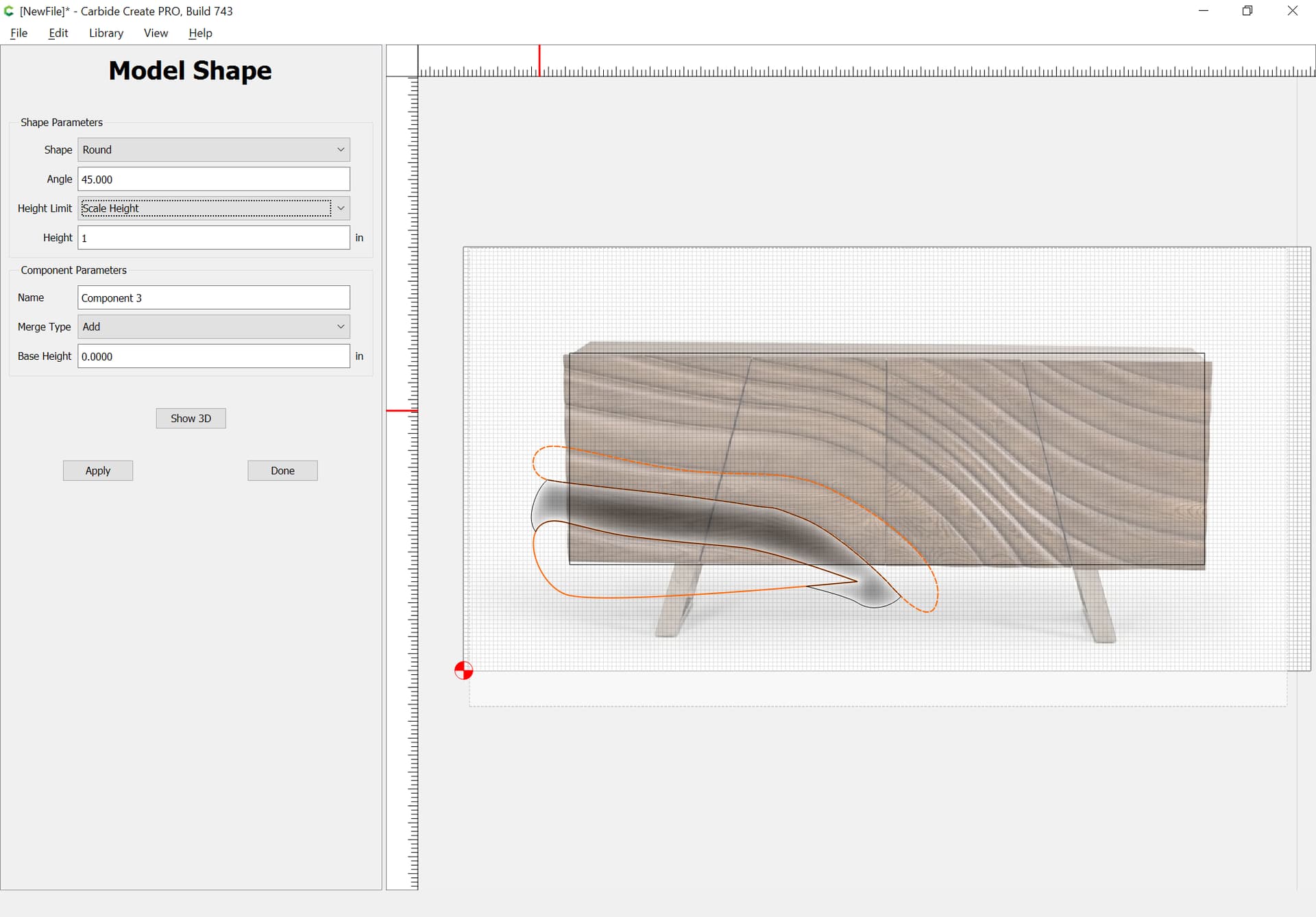
This can be done more quickly by alternating which are done, and then using the previous two regions to make the one in-between using Trim Vectors/node editing.
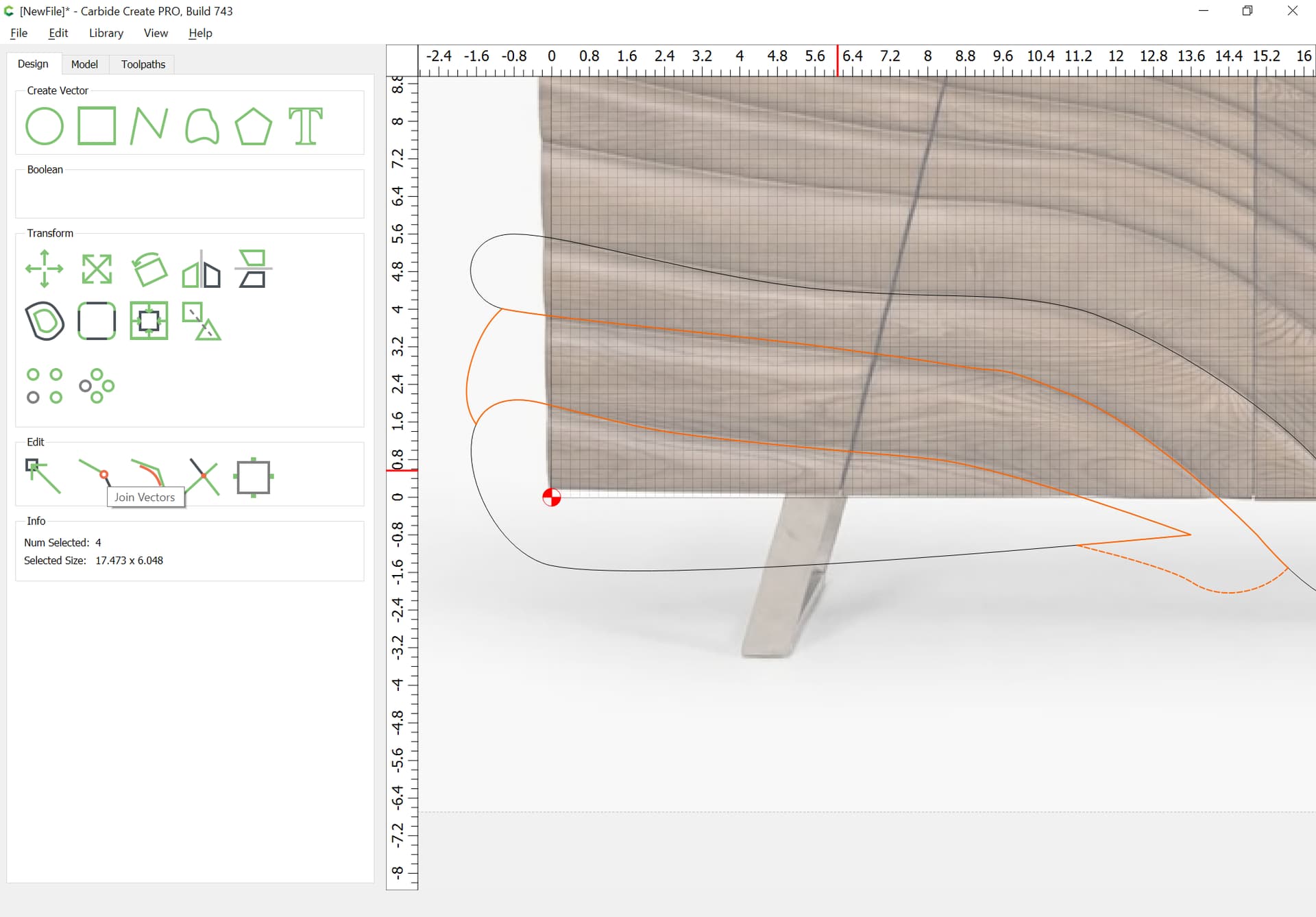
Repeat this until all the necessary geometry is drawn.
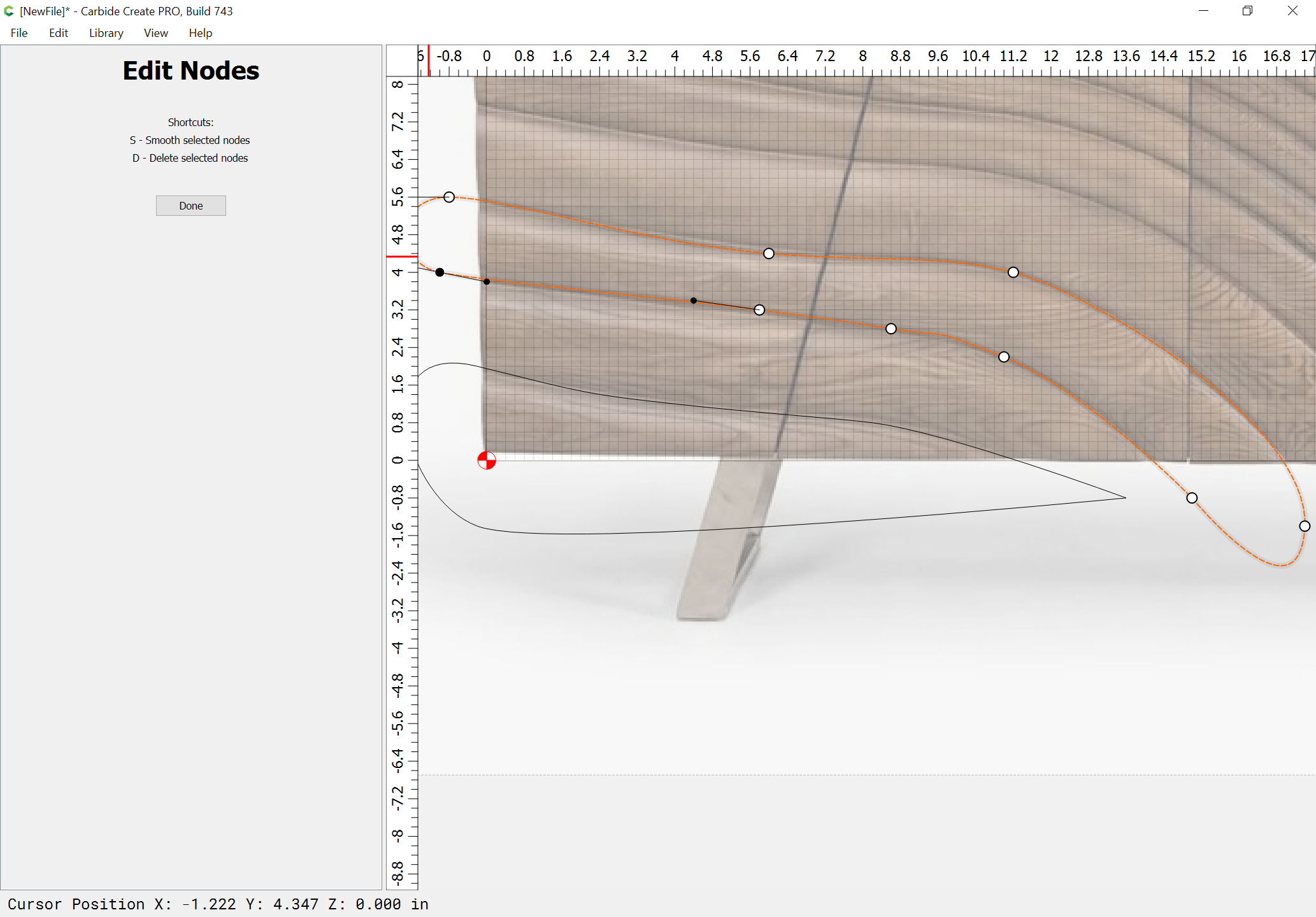
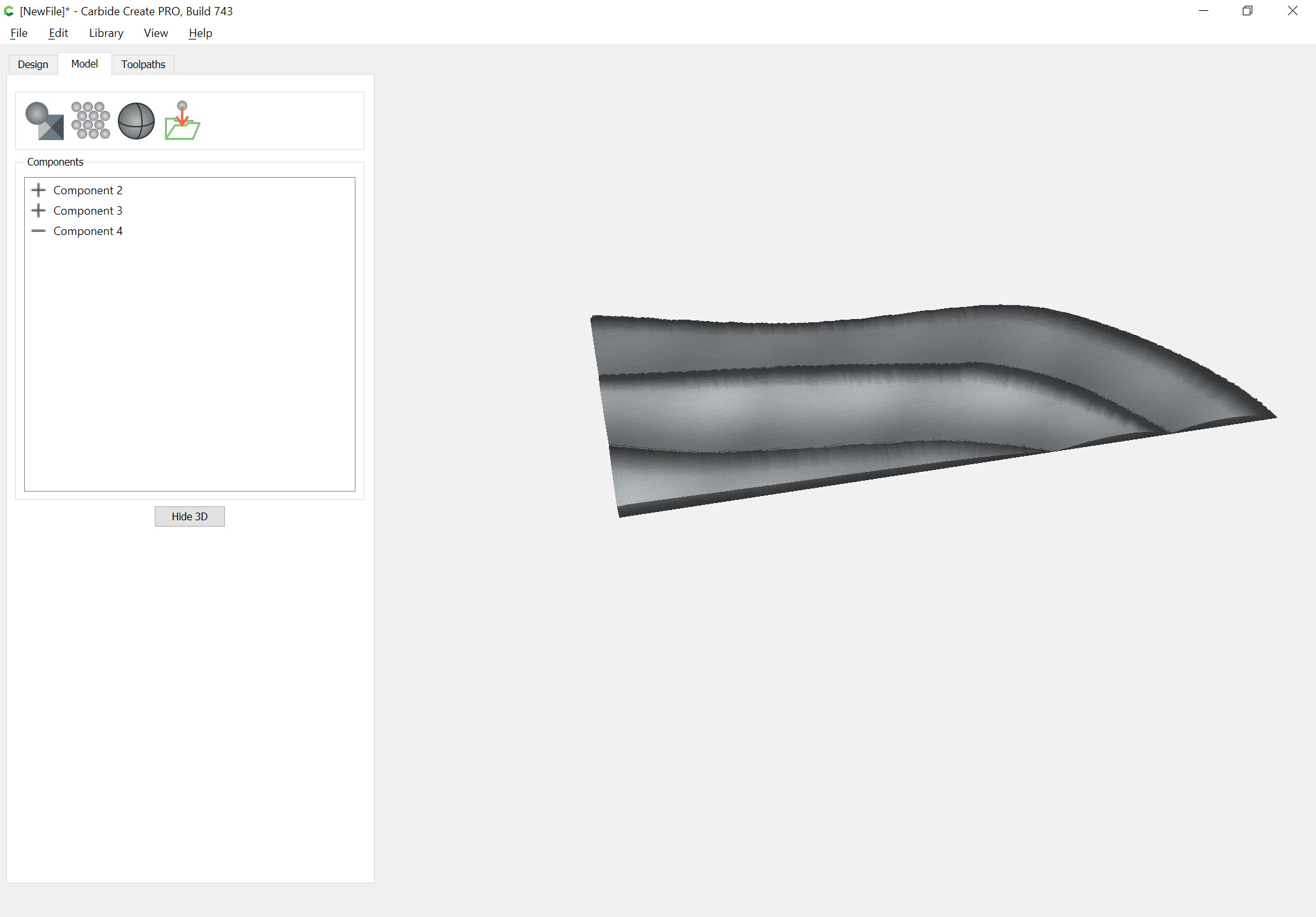
It looks as if the surface is asymmetric, rounded more on one side than the other — this will require dividing the geometries further and modeling in sections — could we get a profile view to confirm?
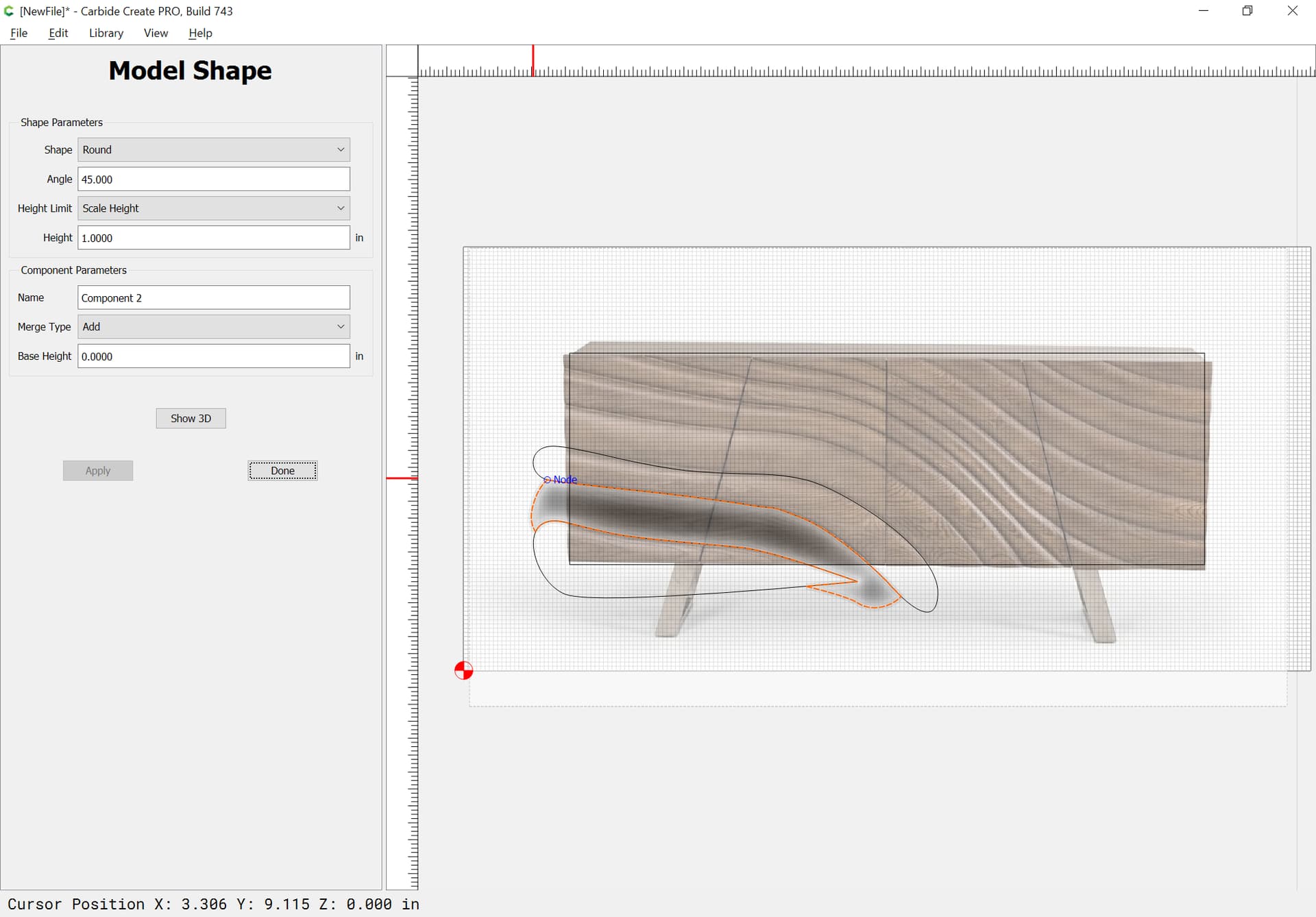
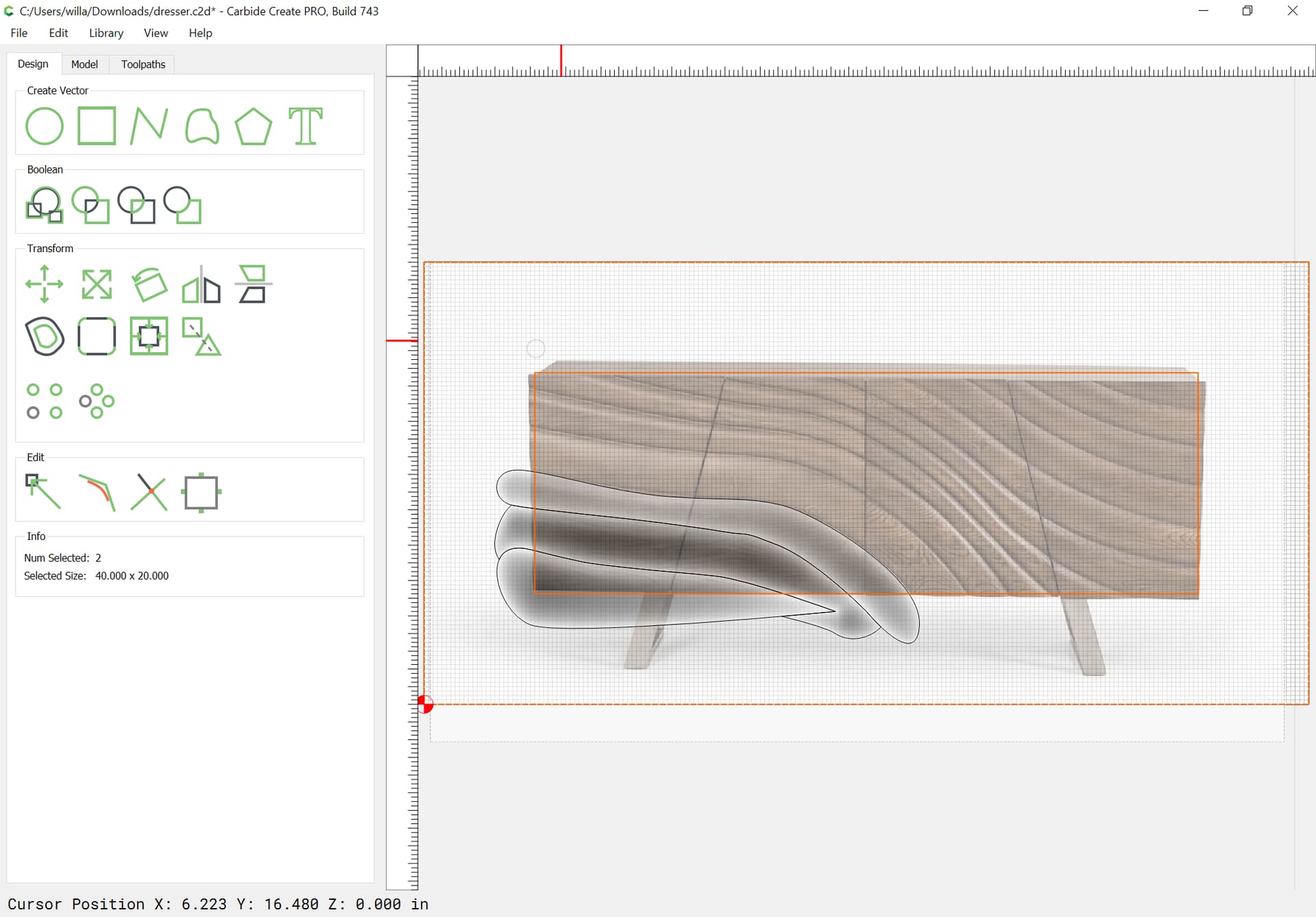
Then scale everything to the final size and set the design into a smaller portion of a larger stock area and model, something like:
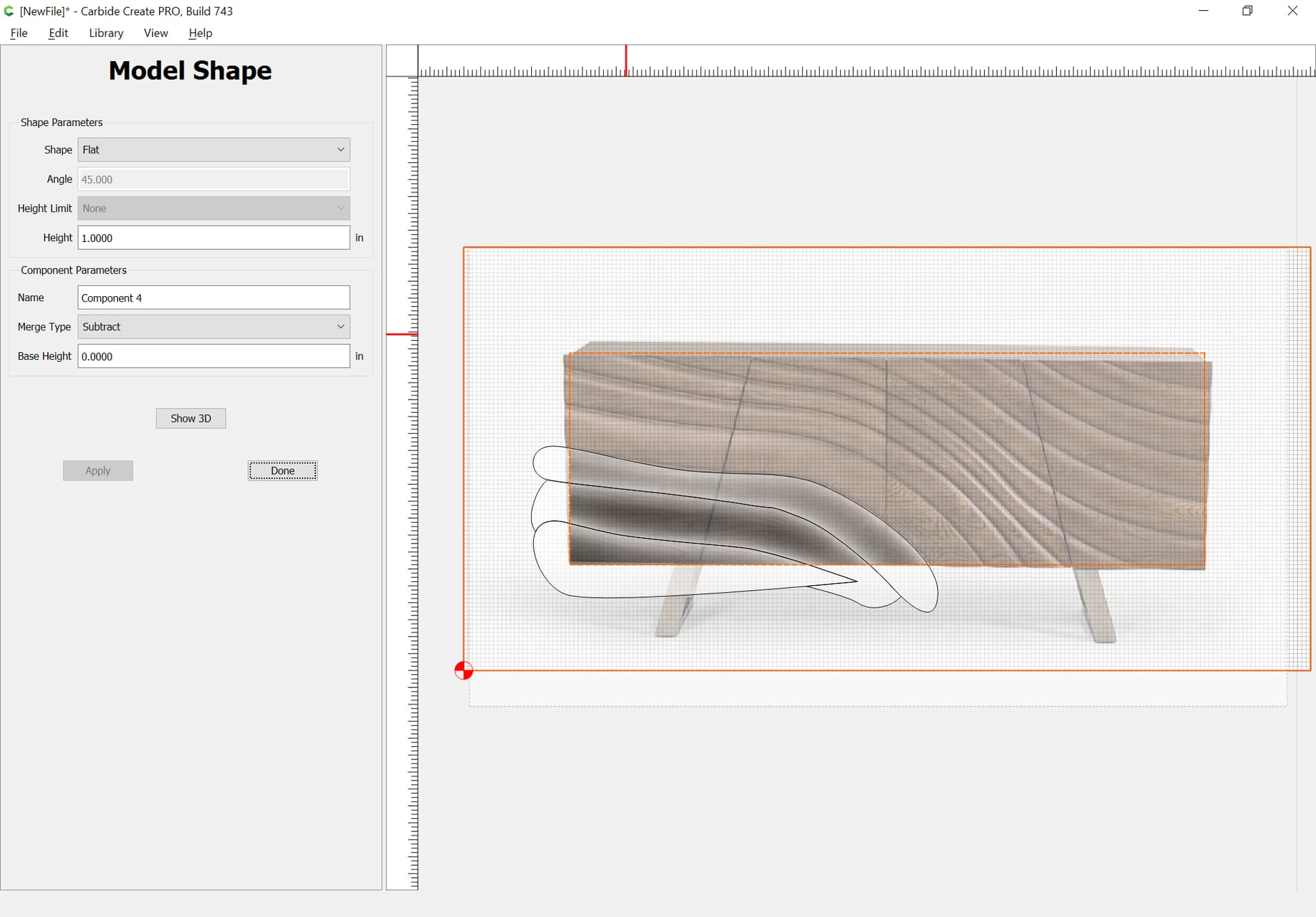
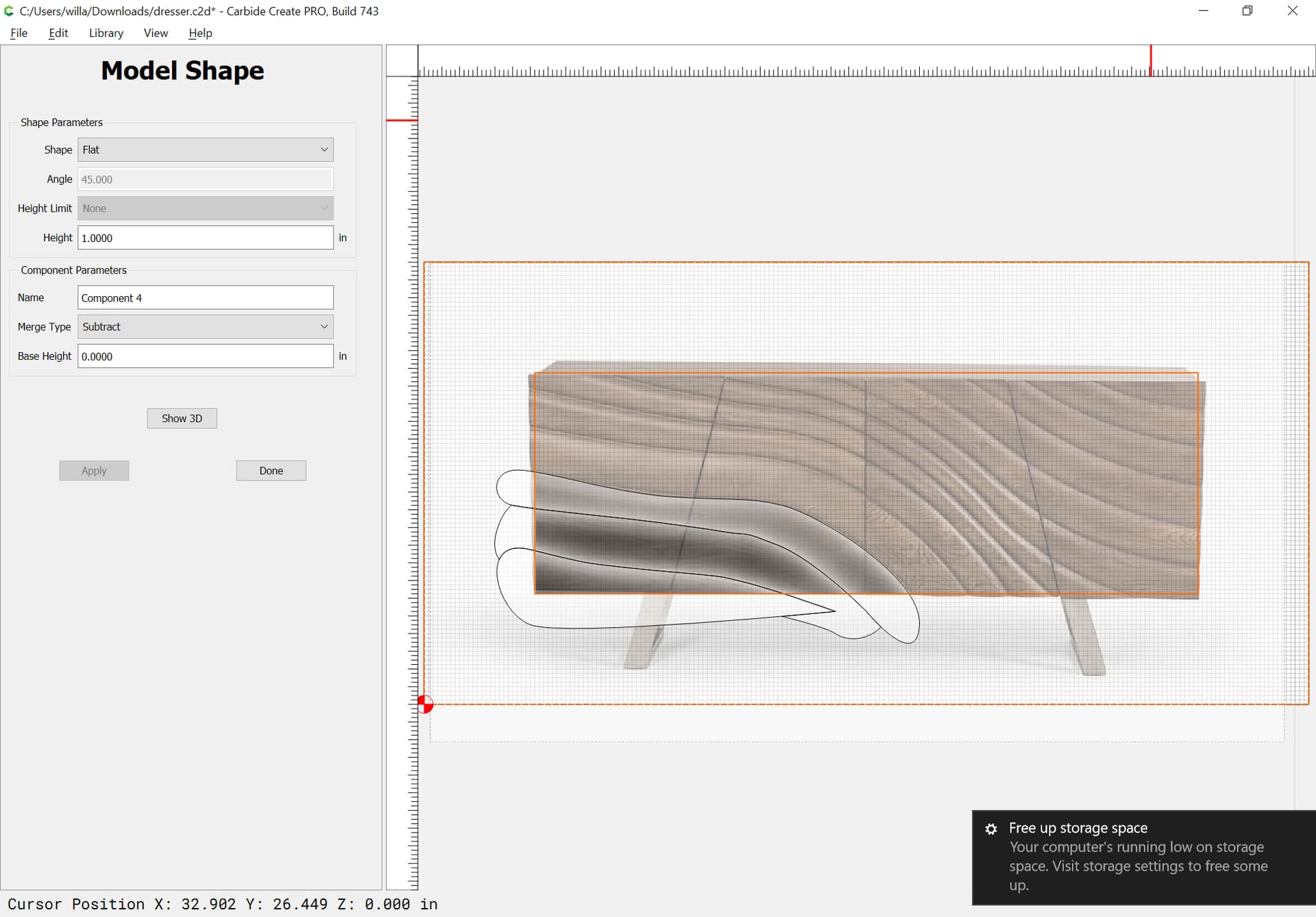
Thanks so much. This appears to be exactly what I need. I think I follow the process up to the part where “and finally, remove the geometry around the edges:”. I’m not sure how this is done without changing the edges of the model. In order to keep those edges square. Your model edges look perfect.