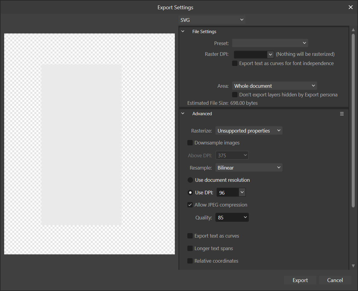
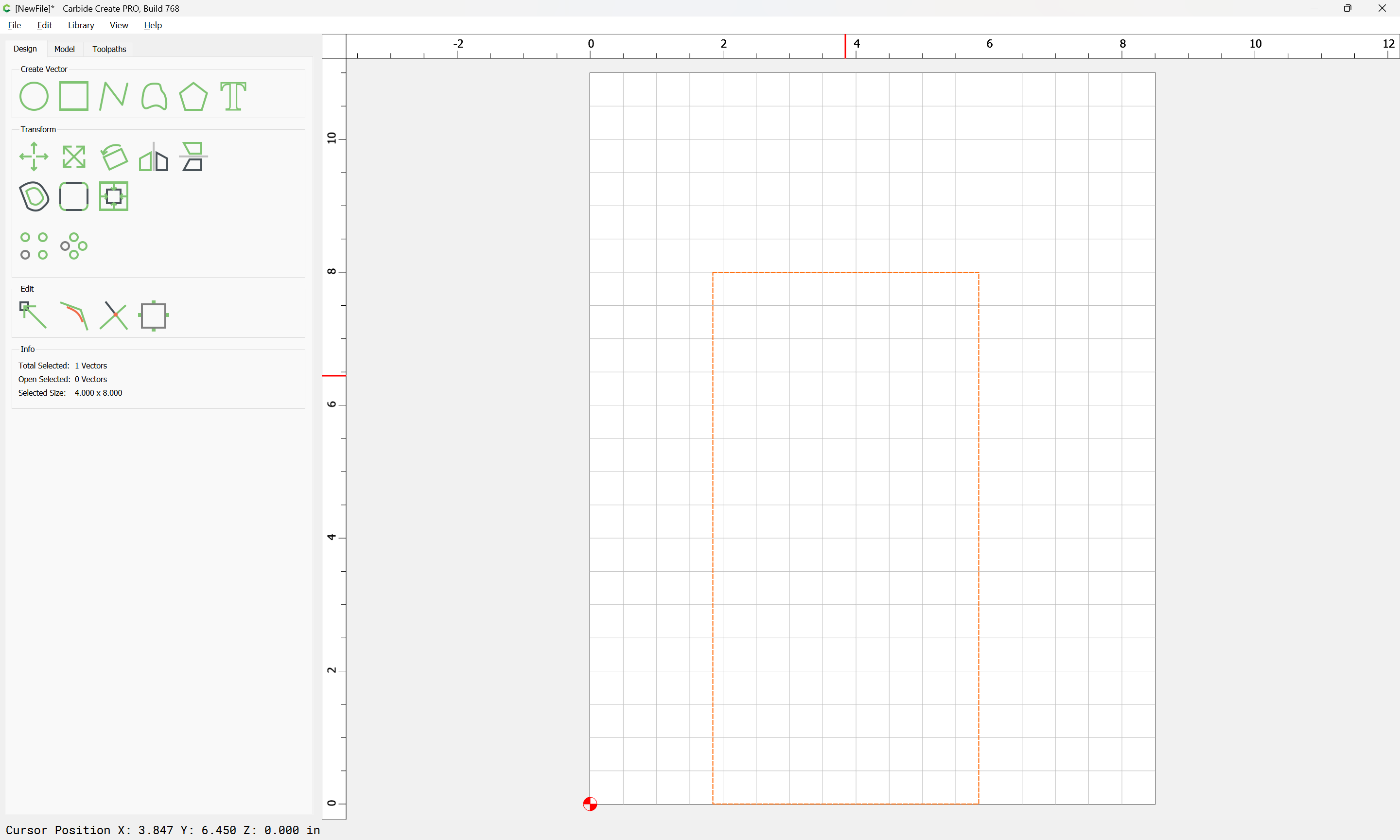
When creating a line using stroke and no fill in affinity designer 2, I want to leave it as a single line for a border that will be a shallow groove (contour cut), using different bits depending, and have the bit follow down the exact line . Can I export the svg at 96dpi for use in carbide create as a stroke or does it have to be converted to curves and expand stroke applied? When converting to curves and/or expanding the stroke it becomes 2 lines (for the outline of the stroke) which I don’t want. Just want the bit, whichever I use, to follow a single line.
Am also using vectric cut2d and when I convert to curves and/or expand the stroke in affinity designer 2 and export the svg, it also shows the 2 lines that I don’t want. Am wondering if carbide create and vectric cut2d work the same way with these svgs? I keep reading that in affinity designer, as a stroke it is not yet a vector, and so you have to convert to curves and/or expand the stroke, and that is what seems to confuse me. Doing this creates the 2 lines, but leaving them as strokes in affinity designer works, but doesn’t seem to be the correct method to do this.
When carbide create (and cut2d) export the same file as an svg, they appear back in affinity designer as strokes but they are vectors (have nodes so they must get converted to curves in the process) or the affinity designer stroke only non vector is seen in these programs as vectors upon importing. Thank you and hope this makes sense and someone can explain the correct way to create a simple border line in affinity designer for export as an svg.
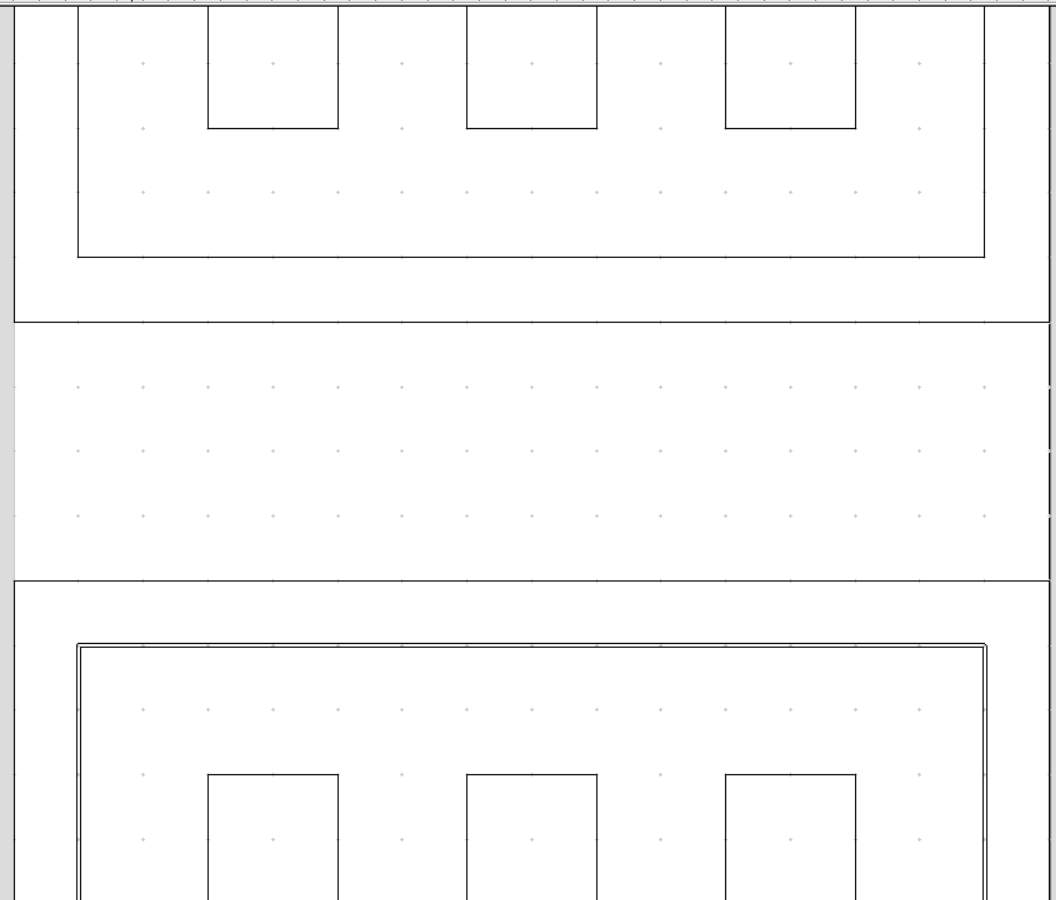
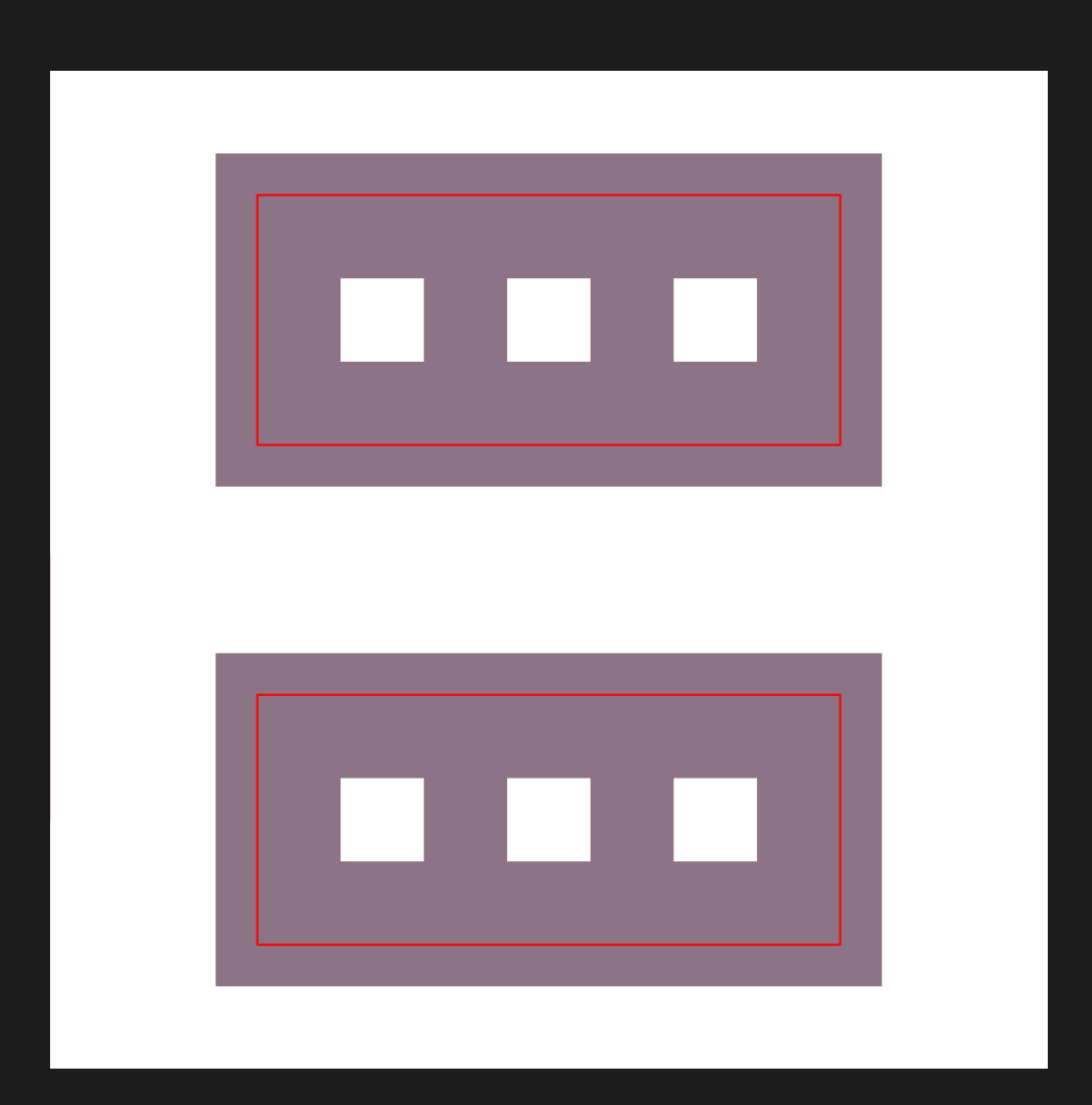
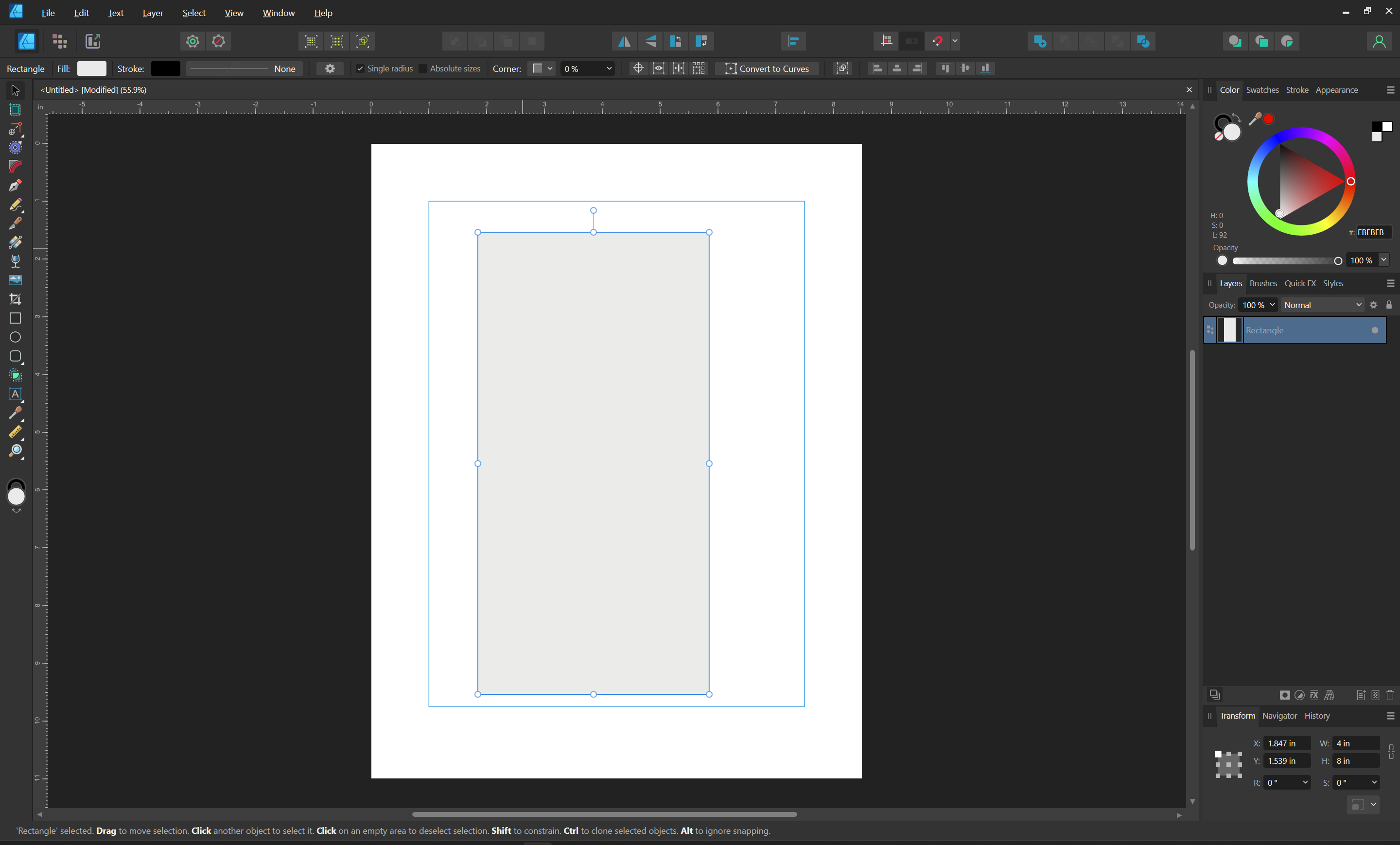
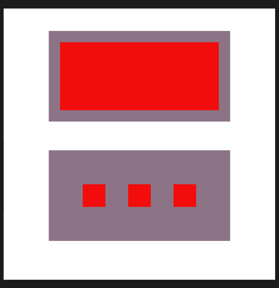
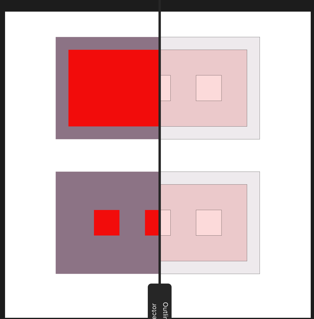
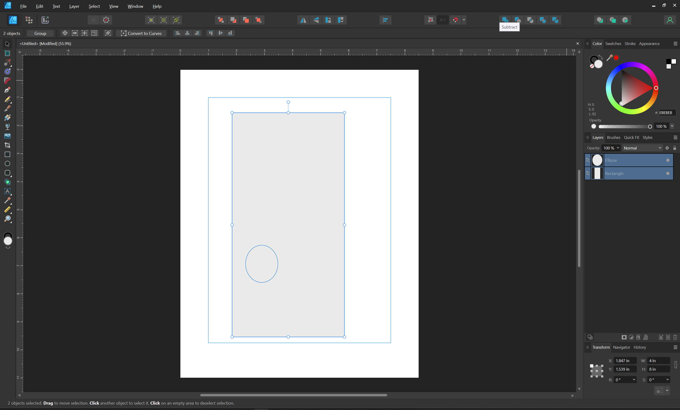
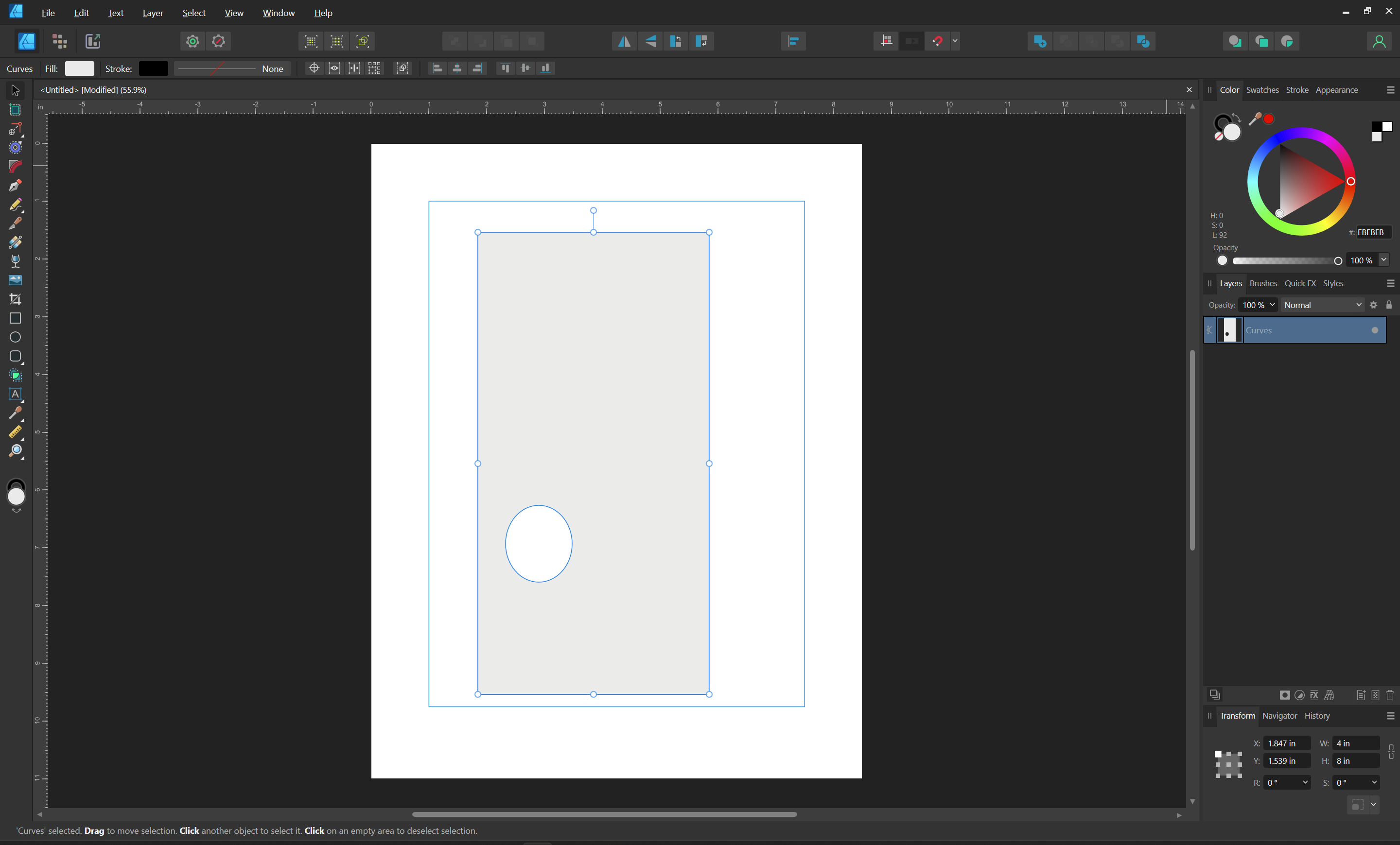
Thank you Will. Sorry I’ve got myself so confused over this. Here is a simple example. In the affinity designer photo the top shape is stroke only and the bottom shape is fill. In the 2nd photo the top is what I need (stroke only), but with fill (bottom shape) it gives 2 lines.
it works fine in carbide create and cut2d, it’s just not appearing in affinity designer as I’m expecting and that is where I’m confused. Just have to get a better grasp.
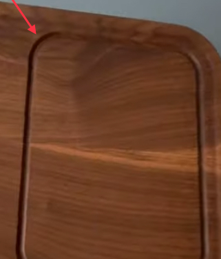
In the design program then you would represent the groove, like in the photo except mine needs to be as thin as the tool tip, with a fully filled shape? Is that just so you get the required vector for the cam program?