Here is a basic tutorial on parametric design in Atom 3D
Recently @wmoy described using parametric design in Autodesk Fusion 360 — my most recent parametric design was a CNC clamp accessory organizer:
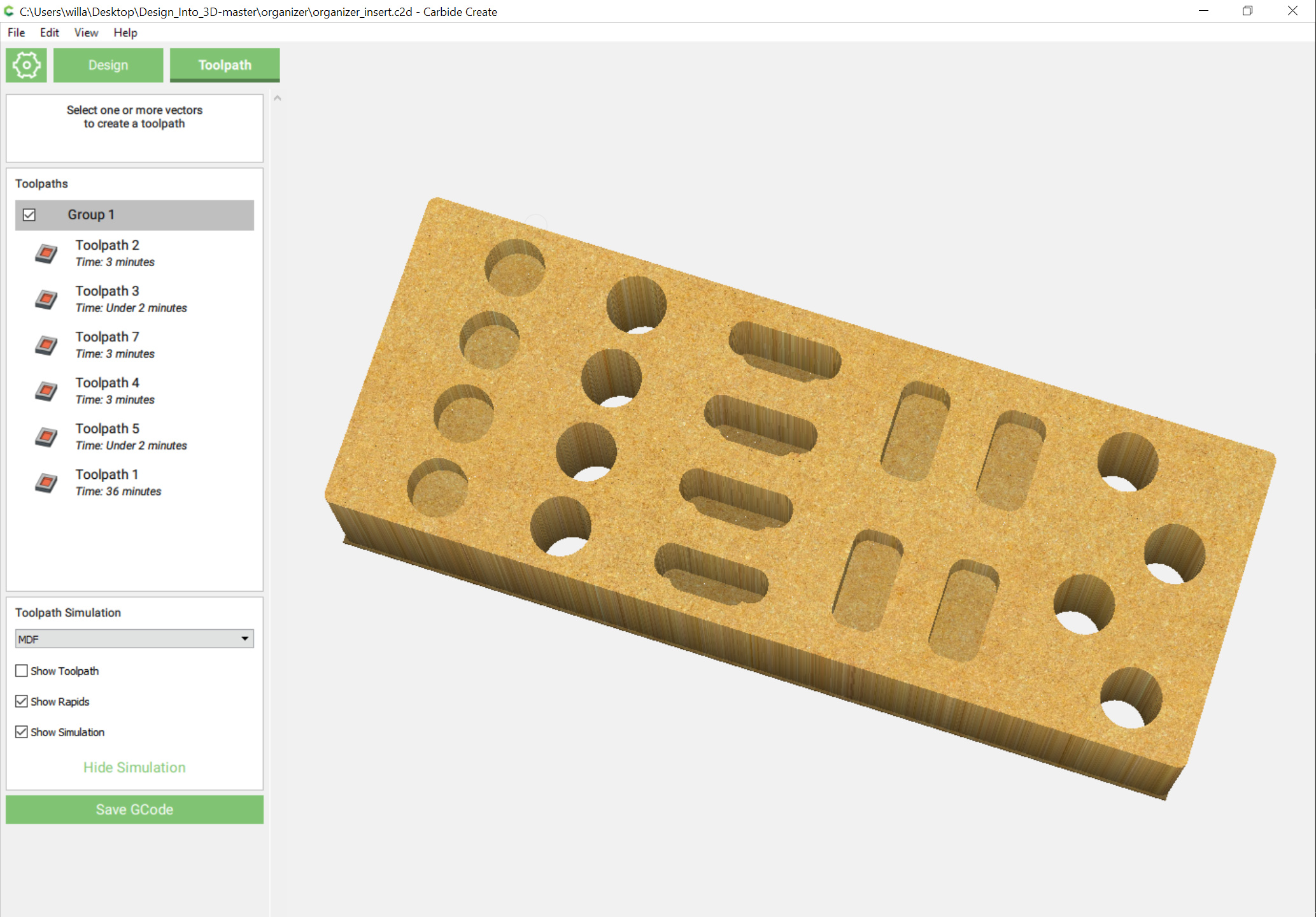
which I have not yet gotten around to making parametric in OpenSCAD.
Alibre has an example file on this here: https://support.alibre.com/support/solutions/articles/27000047176-shelf-use-global-parameters-to-make-endless-combinations-in-seconds
Here’s how to make a much simpler organizer parametric in Alibre Atom3D.
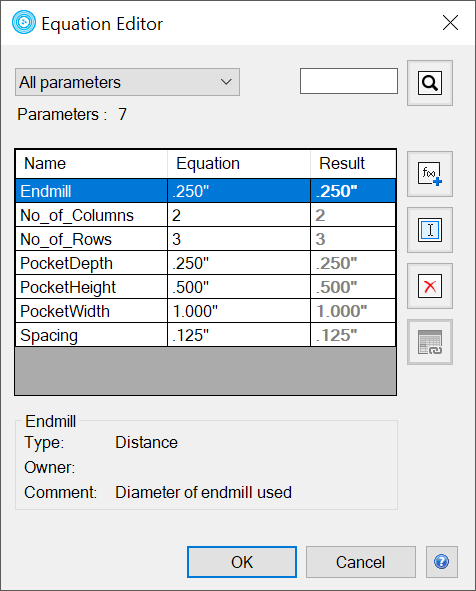
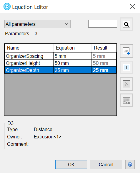
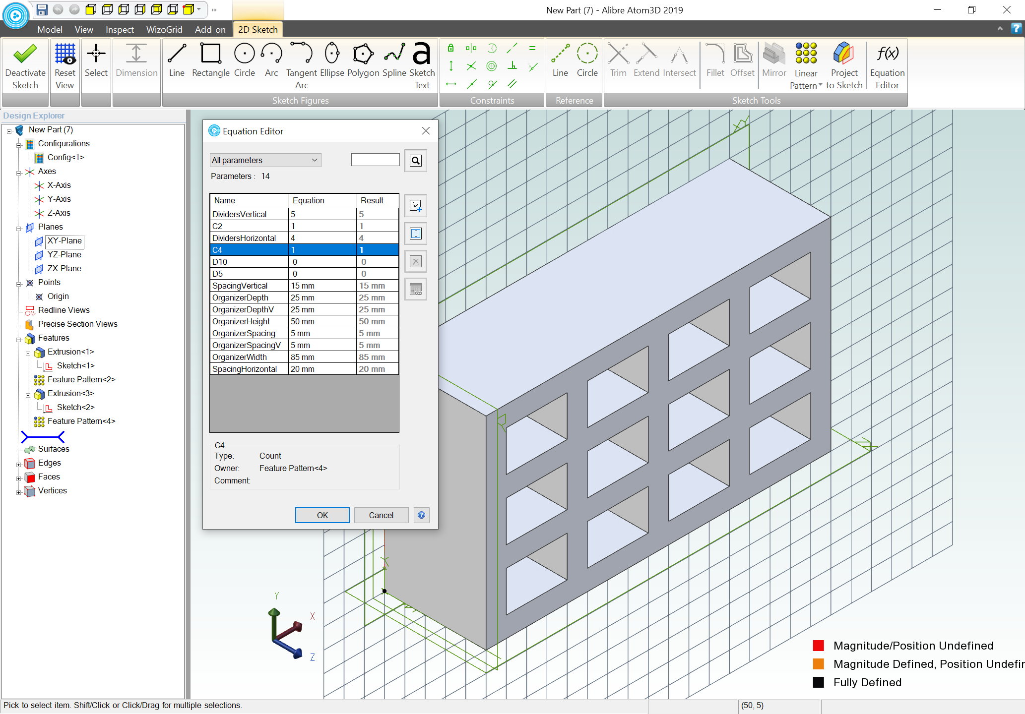
In theory one would start by using the Equation Editor to make the values which you will need:
Instead we will use Wizogrid from Wizotools:
Turns out that in order to get a 2D elements dimensions as parameters in the Equation Editor one must assign them to have dimensions. Proceeding on that basis.
1 Like
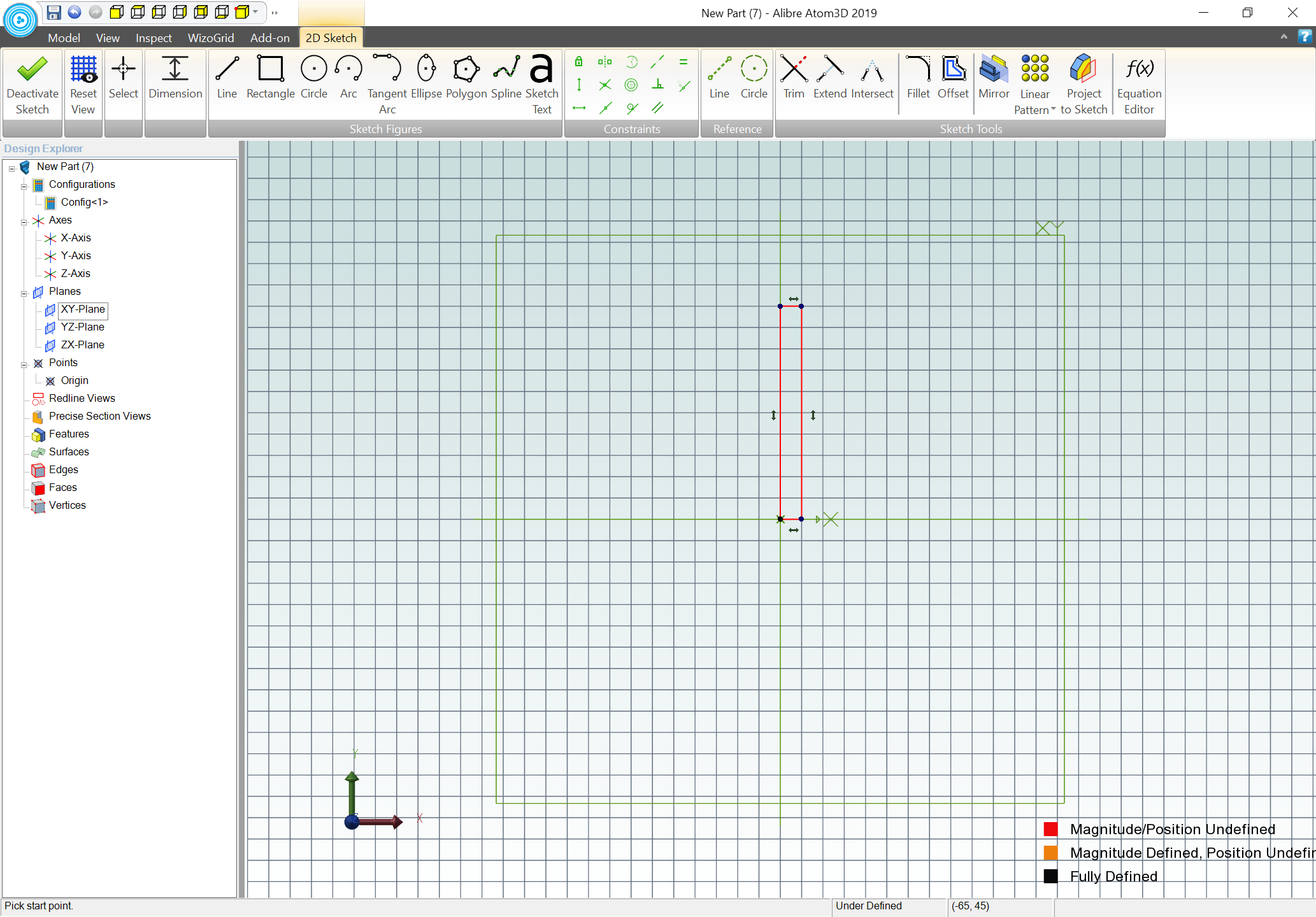
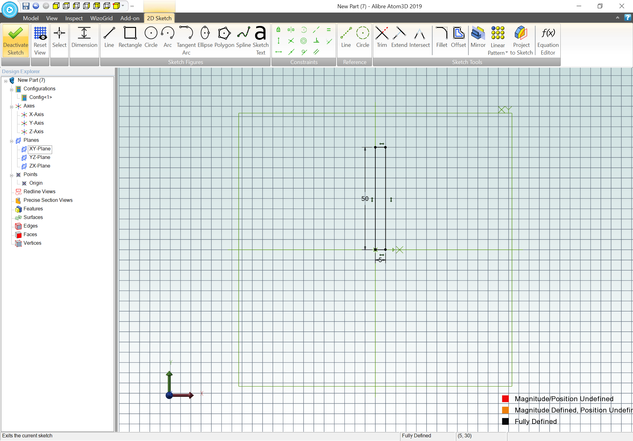
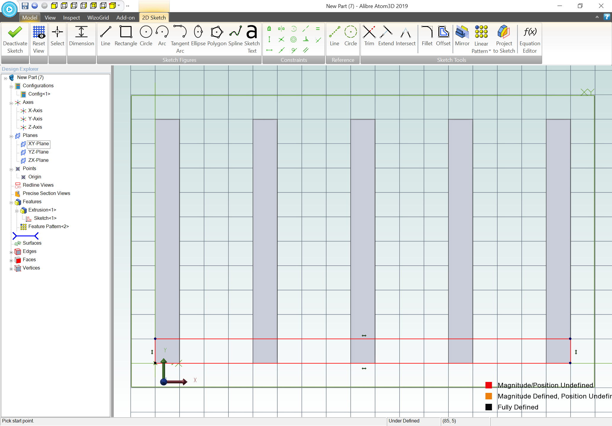
Start with a new part, and familiarize yourself with the icons in the top row of the title bar which allow changing the current view. Units will be metric and grid spacing 5mm, drawing in the XY plane, activate 2D Sketching and draw a 5mm wide (X) and 50mm tall (Y) rectangle which begins at the origin point:
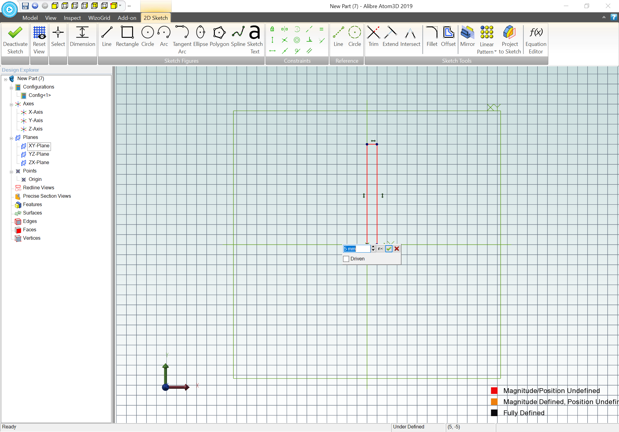
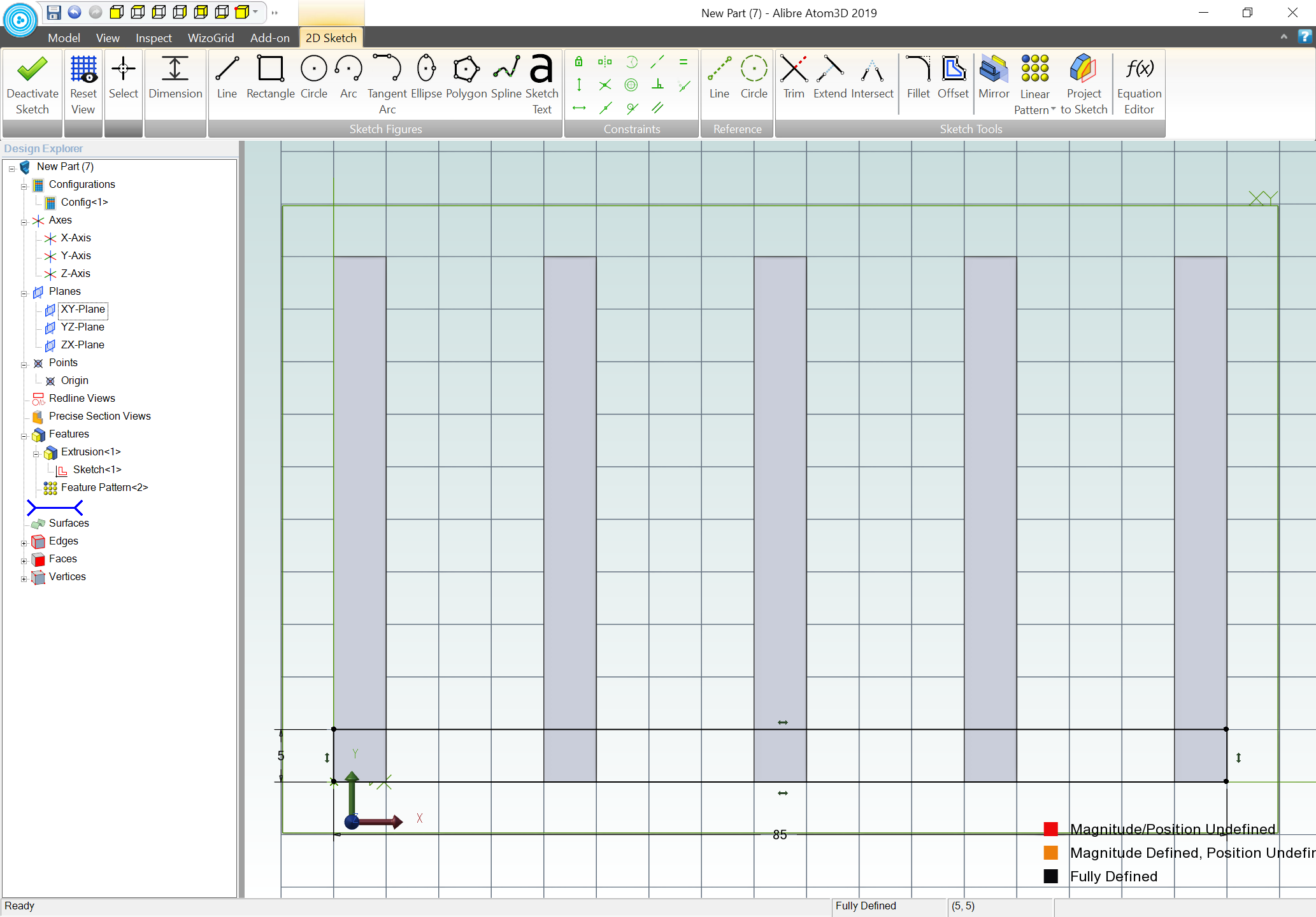
add dimensions for the width and the height:
Deactivate the sketch and extrude to a depth of 25mm:
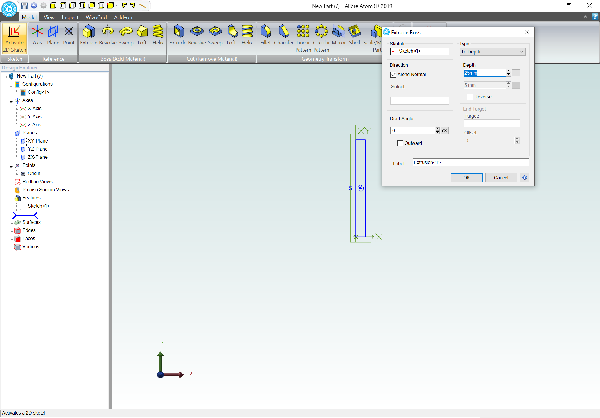
resulting in:
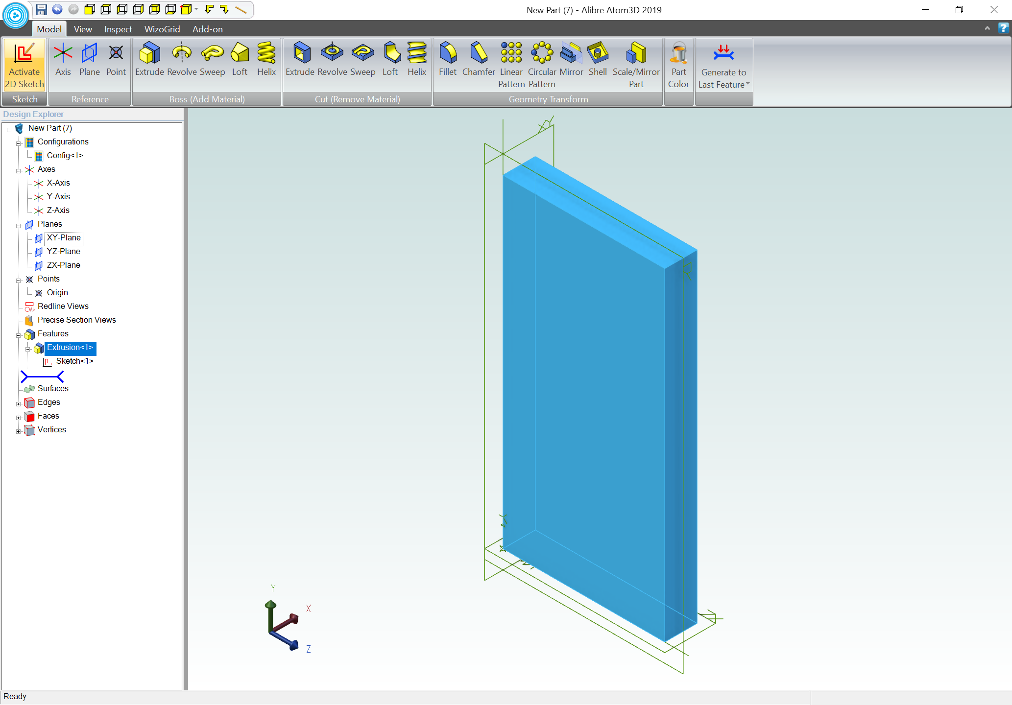
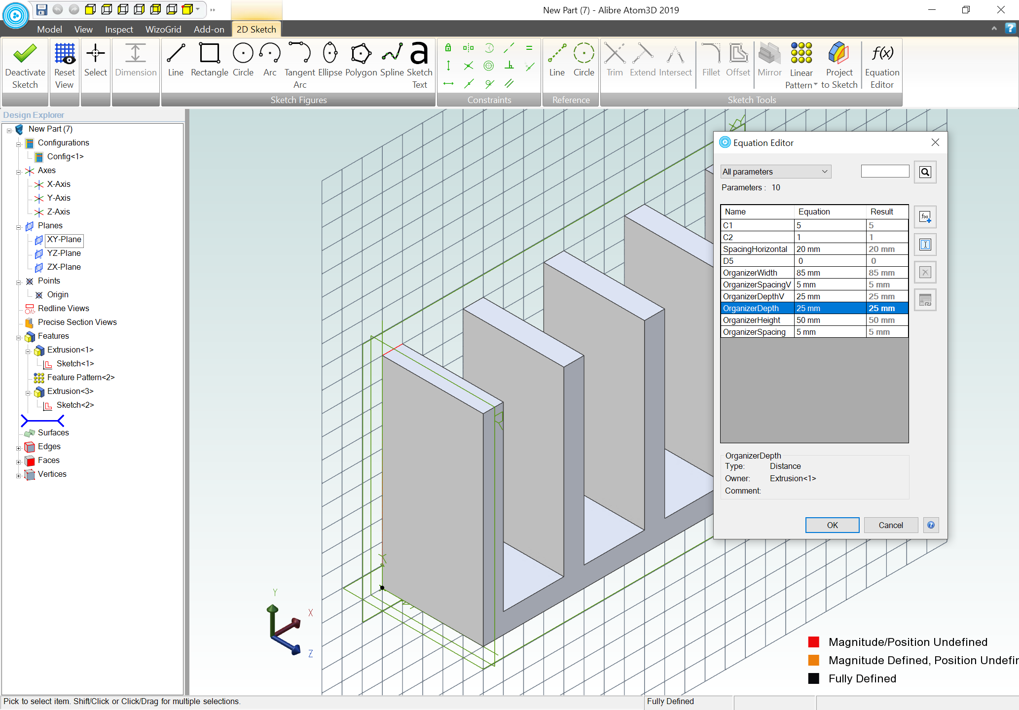
Activate the 2D sketch again and rename D1, D2, and D3:
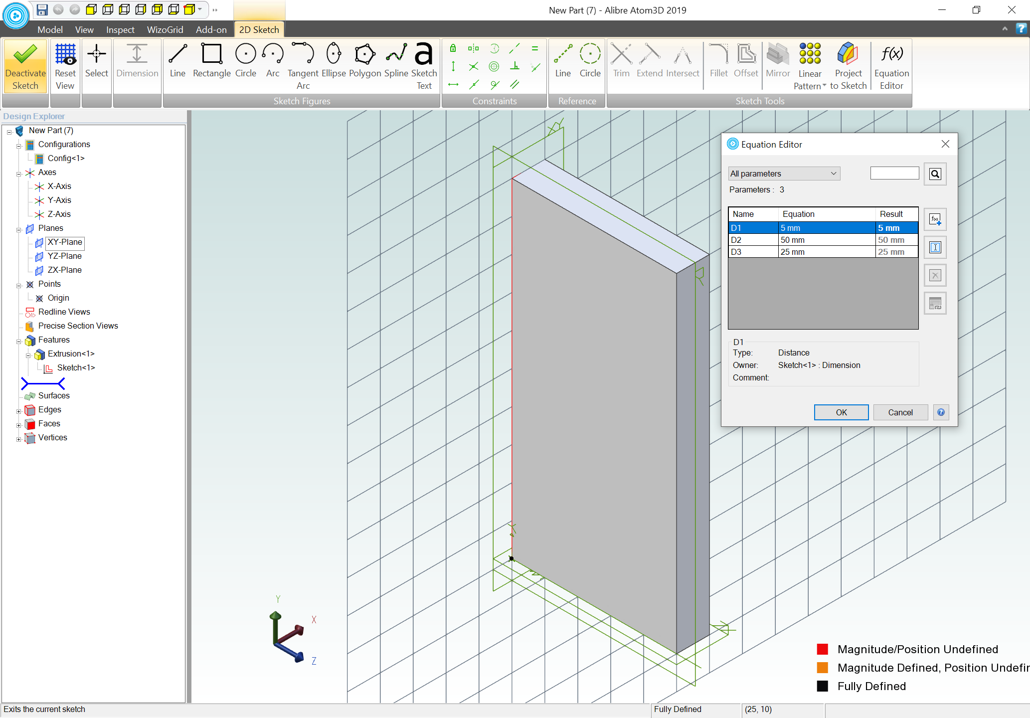
appropriately:
Return to the Model view, force a re-draw, switch to a front view, select the XY plane, then the rectangle, and choose Linear Pattern:
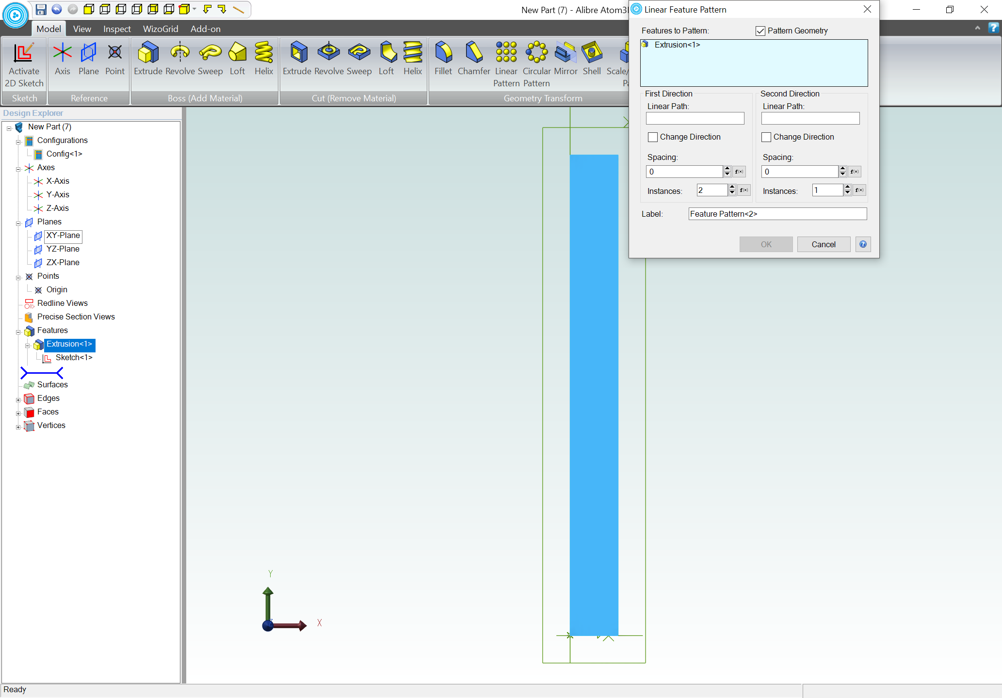
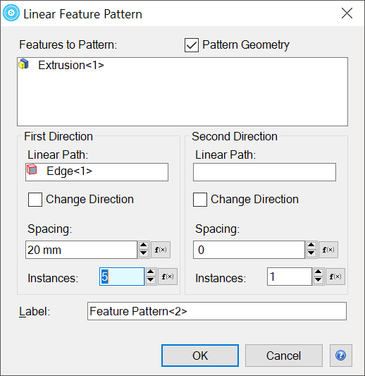
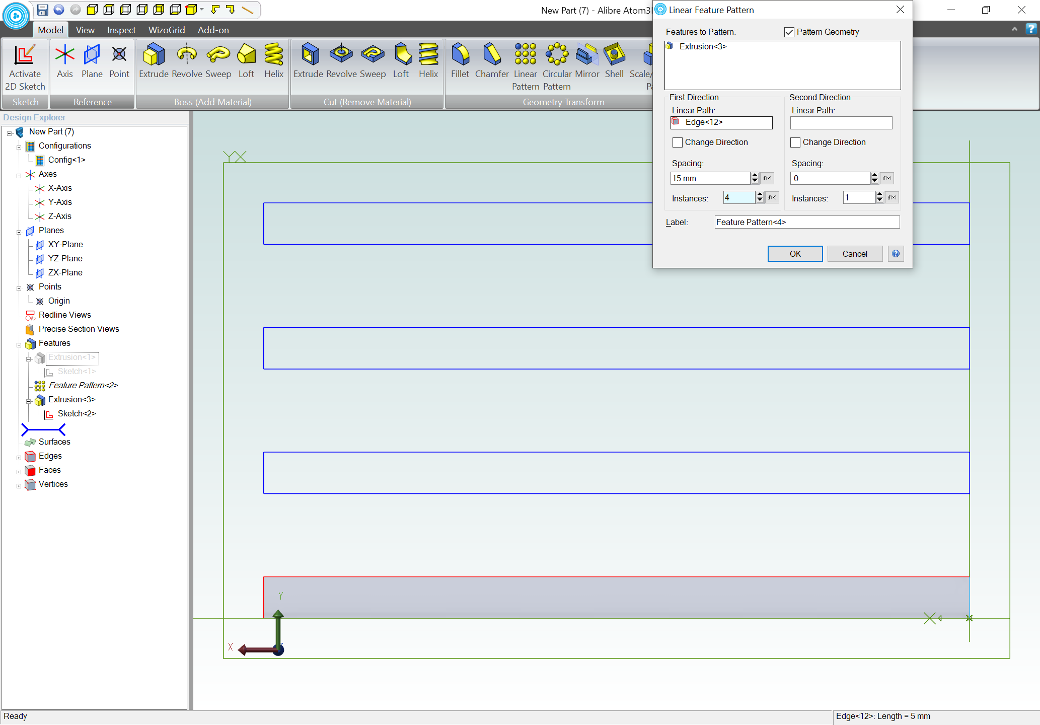
Click in the Linear Path text box on the left for the first element of the array and click on the top or bottom line (this determines the direction in which the array will fill out), enter 20mm for spacing, and 5 for the number of instances and click OK:
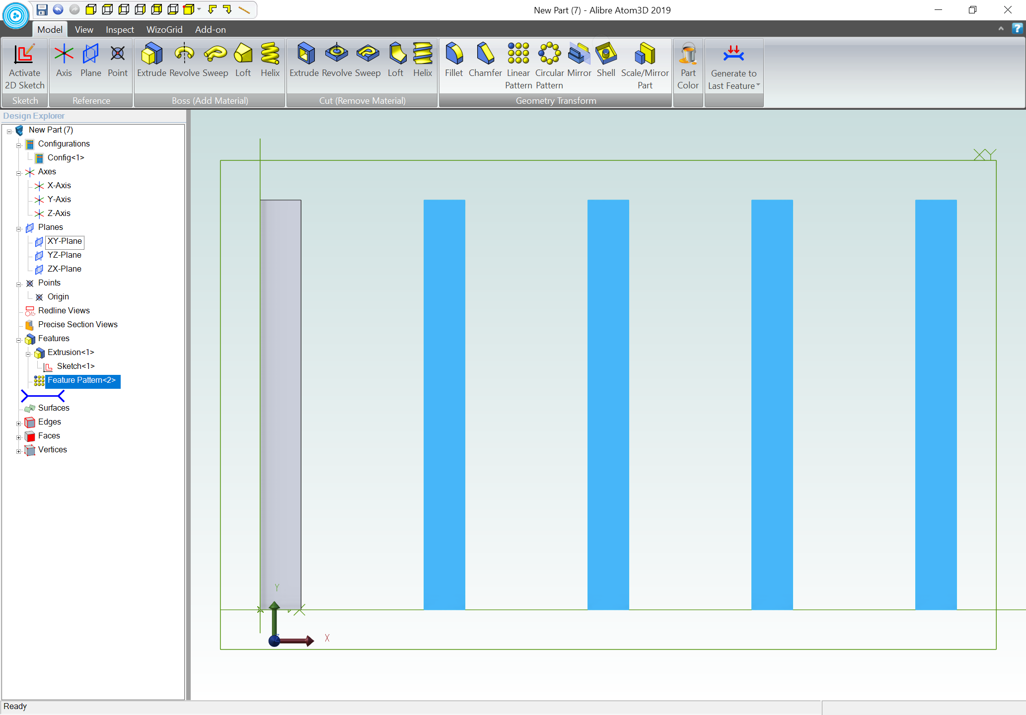
resulting in:
Go back in to 2D Sketching and draw another rectangle beginning at the origin, this time 5mm tall, and 85mm wide:
Again, dimension the width and height:
switch back to Model view, extrude to 25mm thick, and then go back to 2D sketching to name the new dimensions:
Select the newly made extrusion (it may be necessary to temporarily suppress the previous one) and do another Linear Pattern, this time selecting a vertical axis, 15mm spacing, and 4 instances:
and once again, it will be necessary to name the new dimensions:
1 Like
At this point, all that is left is defining the parameters and formulae in Wizogrid:

The formulas are obvious:
=B2+1
=SET("DividersVertical", D2)
=B3+1
=SET("DividersHorizontal", D3)
=B4+B9
=SET("SpacingHorizontal", D4)
=B5+B9
=SET("SpacingVertical", D5)
=SET("OrganizerSpacing", B9)
=SET("OrganizerSpacingV", B9)
=SET("OrganizerDepthV", B12)
=SET("OrganizerDepth", B12)
=B5*B3+(B3+1)*B9
=SET("OrganizerHeight", D15)
=B2*B4+(B2+1)*B9
=SET("OrganizerWidth", D16)
and to add a bottom…
I will note that this file was made the opposite from how I initially planned, since I couldn’t work out how to center the parts.
Attached. endmillorganizerparametric.zip (53.8 KB)
This topic was automatically closed 30 days after the last reply. New replies are no longer allowed.