Ive been trying to cut a table top (for the workbench the XL will sit on) which requires a slot, and I want to add in a pocket for the shapeoko feet. Left side, A-OK. Material hung out under the Y axis. Go to do the other side, and not only cant I zero to that side with the probe, there is no way in carbide create to set the lower right as toolpath zero.
Between this and having to zero the thing if I think about something else too hard in the shop… man, this machine is pissing me off.
But you cannot set that as zero in Carbide Create. Also, the touch probe does not have any way to adjust when zeroing to any other corner other than front left.
Oh, to achieve that effect in Carbide Create make the working area larger, then set the zero to be the center, then put all the toolpaths in the upper left corner — you can extend beyond the stock area, it just won’t preview in 3D.
Jog to where you want zero to be. Send G10L20X0Y0Z0 to zero all axes.
Oops, misread. I thought you said without the probe.
You can send probe commands through the MDI, but you’ll have to send one at a time. This would be easier in a different GUI where you could set macros. UGS or CNCjs
The probe only aligns to the lower right corner. You can’t use it for the right side of the probe. Just he say it is. Means you need to basically either do it the “old fashioned way” (can still use it for Z), or use a different tool (UGS an do this) - it’s a limitation of carbide motion.
Got to say, Im pretty frustrated that after spending money on a machine that had decent reviews, to be told in the official forum that the software cant do basic functions (I’ve seen chinese lasers that can adjust origins, and they cost like $50 USD), and to go find another control software.
Its not going to be my main use of the table, but would be a limitation for most things I would try to do with it as a hobby item. Next you guys will tell me that the board isnt going to work, and Ive got to drop another grand or 2 into basically replacing everything but the power cable to do 3d routing.
Your work origin can be set anywhere in your machine space. Where you set it in your CAD might be limited by the software you use to design. Occasionally, one must be creative in solving a problem to use the tools available. Alternatively, one can learn to use different tools.
It sounds like you’re trying to carve some pockets in the corners of a rectangular workpiece that is bigger than your work area? Sounds like this could be easily done by rotating the workpiece. If, for some reason, you must do it with zero in the lower right, this can be done as explained above.
I’m sure if you describe your design, or better share your drawings, models, plans, you’ll be able to get help to solve this.
The software is embarrassingly simple, and was available in advance for testing and evaluation. If you wish to do things in a fashion which the software doesn’t support there are many options which may work as you wish as noted at:
If Fusion 360 won’t work for 3D for your needs, please let us know what sort of work you’d like to do and we’ll do our best to offer a suitable free or low-cost option.
Yes, that was exactly what I wanted to do, with a pocket for the machine feet, and with using the touch-probe to zero out the tool (one of the main reasons I bought it… I can use an indicator to zero, but its 2018!) for that corner.
I was cutting channels and rounding corners on a 48 x 22 board hat was to be the new table top… for the machine itself. Being able to stick the work piece outside of the envelope and flip it allows you to do larger pieces, if you are careful, and get some nice results.
Lack of mini portal gun to get the bit to cut up from the bottom of the table if I flip the piece over to do the other corner. What I ended up doing (which looks a bit shoddy) was just cut the pocket I needed on the wrong size, used that to center, drilled through, and make my own pocket with a forstner bit in a dill.
Nope, not in the working envelope that you have when part of the work piece sticks under the Y gantry. You only have about 2/3 the bed available with the current Z axis design, and I was cutting a board that was 22 x 48.
I might be wrong, but I thought the gantry was the assembly that moves along the Y “rails”. Anyway, so you’re on a SO3 regular (~16" x ~16")? I can’t fit anything significant under my rails with my supplemental wasteboard.
I think I can picture what you’re saying, and I would say it’s not a common use case. I can’t think of any sender that has this as a default option.
I will say again…if you don’t want to use a different sender, use the gcode commands to probe from the other side. you can enter text commands through the MDI.
I’ll hve to read up on those commands to get the probe working like that, thanks.
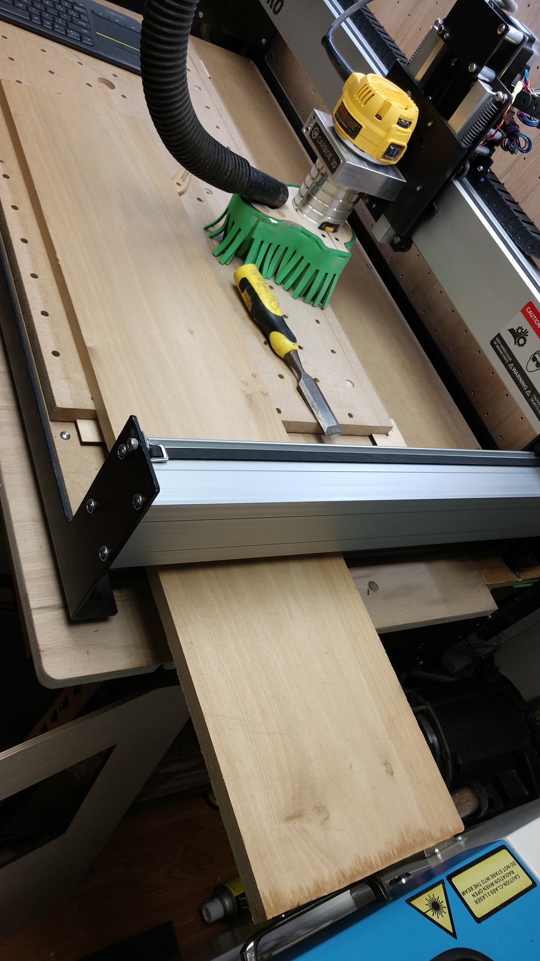
Im running the XL version, and had material sticking out each side like in the photo (this was before that wasteboard was installed), one side at a time, to work with an oversized piece. Figure I cant be the only person to work a larger than workspace part like this, and want to be able to work both sides.
On an XL, I would rotate that 90 degrees (long edge parallel to Y) and cut two corners at once. Rotate the thing 180 and repeat. Makes it easier if you don’t have the machine against a wall. What you’re doing is called tiling, and, you’re right, it is a common thing. Typically this would be done along the Y axis, so you can pass the work through, maintaining a zero reference.