Hello. I’m looking for recommendations how to mill standard pockets at an angle to the XY plane on a large piece of material. I’ve seen examples using vises to clamp smaller stock at an angle to the spindle, but my stock starts out roughly 20" x 14".
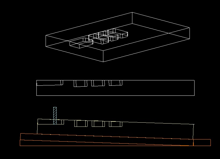
This is a simple iso and side view drawn with pockets angled 2 degrees to the material top. Since the pocket walls need to be 90 degrees to the floor of the pocket, I assume it has to be cut with a flat bottom end mill. So my thought is the work has to be tilted up toward the cutter. (This is the inverse of how it would be done on a router table)
I worked for a shop once that did a recurring job like this with a hinged workholding fixture. I remember it being a lot of setup time to locate the supports properly and validate with registration holes because the hinges had some slop. It required either drawing or programming in offsets since the XY coordinates shifted from when drawn flat. I have some ideas how to do all this but my machinist knowledge is limited.
Someone suggested this could be done without tilting the stock using a flat bottom cutter that flares outward toward the end. I can’t say I know of such a cutter. That seems like it would require a very complicated toolpath with hundreds of shallow passes to get square walls and smooth floor.
Any thoughts or recommendations are welcome…thanks.
I’ve done something similar in the past and did it with creating a wedge from scrap cut to the angle I wanted, secured that to the wasteboard and then the stock to that.
It appears you will be cutting at the leftmost and possibly zero position, so if that will be your Z-zero, so you shouldn’t need to adjust your retract height to avoid the tool crashing through anything as it moves between tool paths. If your Z-zero is in the middle, you’ll need to adjust the retract height for sure.
It looks like your ‘middle’ pockets get gradually more shallow moving to the right, so you also shouldn’t need to adjust the depth for each, unless you want them to be the same depth. You’ll want to measure down from a level line at the highest point to make sure you are getting the depth you want for each pocket.
Start cutting at top of the stock on the mid pockets you’ll be cutting air for a few passes, so you could adjust your start height on each of those if you want to save some time, but you risk cutting too aggressively on the first pass if you get it wrong.
Hope that’s at least somewhat helpful, but it’s likely everything you already thought of
The hoodgie-widget with the hinges is called a sine board/plate. I made one as part of my apprenticeship, way back a long time ago… It has a hinge & a bar exactly 10" on center, so if you know the sine of the angle you want, you can calculate the height you need to raise the bar using gage blocks.
You can do the same, similar thing just using the length of your material as the hypotenuse, and shim up the higher end using the sine of the angle you want. sin 2° = 0.0349"
I see you already have it drawn up in a side view, so you can get your measurements & set your zeroes based on that…
Not sure which CAM software you’re using. In CC I would draw up the side view with my part rotated 2° and use vertical lines to transfer the pocket boundaries down to the part. Measure the depth from the side view & program your toolpaths.
Thanks…I should have shown it here better matching how it will be on the table. The “open” pocket at the edge will be towards the back of the table. So with SW corner as X0Y0, the material is elevated in the Y positive direction. That’s a great point about setting Z0 I didn’t think of. The staggered depths aren’t exactly linear they’re specific to each pocket. I agree it will be best to set Z0 off the highest point of the material being cut to minimize crashing risk. Even then still prudent to set a higher safe Z for if when it moves to NE machine origin at the end. I can live with some air cutting Great tips much appreciated!
Sine Plate - I learn something new every time I come here, thanks! I admit I tend to use CAD to “cheat” and measure the angle which I’m sure my old trig teacher would frown at. I’m using VCarve Pro but I don’t have much handle on 3D work in it yet. I have my designs in Turbocad I can inspect to find the needed measurements.
I draw side/section views & measure as much or more than do the math. Although I’m comfortable with either. If I do the side view it also helps me visualize how to build or cut it.
You’ll get a much nicer cut with a standard end mill with the part tipped than you would trying to cut it 3D anyways.
P.S. if you need a 20" piece at 2°, you have to lift one end 0.698"