I’ve just finished assembling a standard size Shapeoko with compact router and 3 rail hold down, thinking I’ve figured out tool paths and find myself all dressed up and no place to go, i.e. pretty nervous about wasting materials. The machine works as advertised, having run the Hello-world file.
My primary use for the router is to cut simple frame plates and similar parts for drones from G10 board. The G10 is 2.36mm/0.088in.
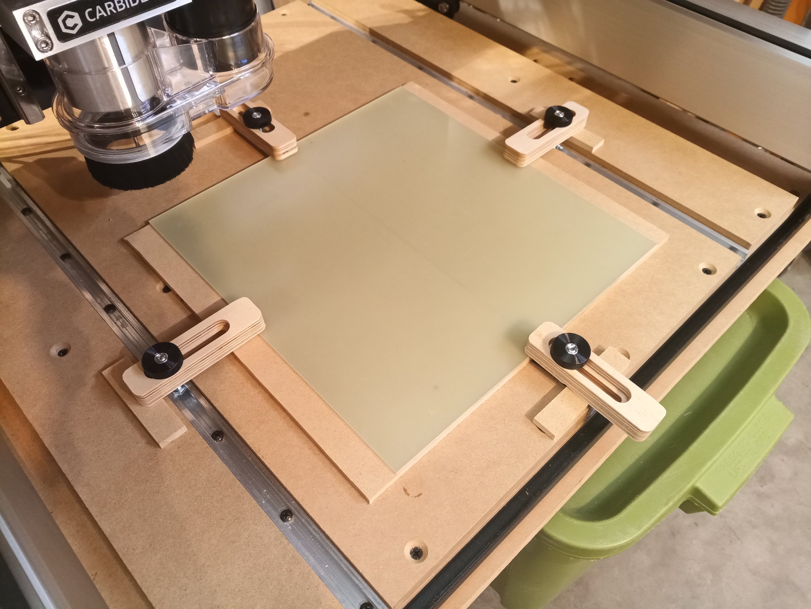
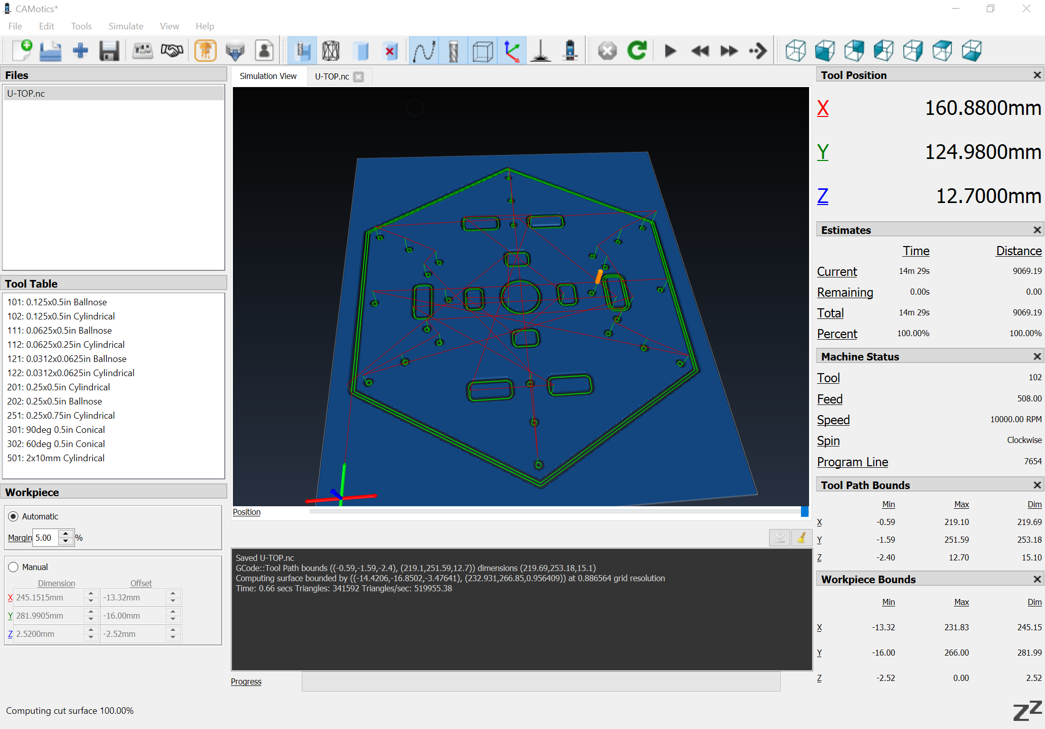
I’ve attached my file and an image of my hold down scheme.
What I “think” is going to happen with the file is that the router will drill a bunch of holes all the way through the G10 to a depth of 2.4mm and cut out the frame plate and lightening holes to a depth of 2.3mm, leaving about .005-6in, which will hold the pieces in place until the job is done.
The question going forward is setting up the hole tool paths. Do I interpret the selection of 'None" offset to mean the mill will go/drill straight down? I watched a video of what appears to be older CC software, which didn’t have this selection and the presenter had to use a workaround of enlarging the drawing holes to .001in more than his .125 mill to be able to use an offset.
Would someone please review my file and hopefully find that it will do what I want? I’ll be using recommended RPM, DOC and feed speed for G10 per the Shapeoko-materials document.
And if someone has a better hold down idea, let me know.
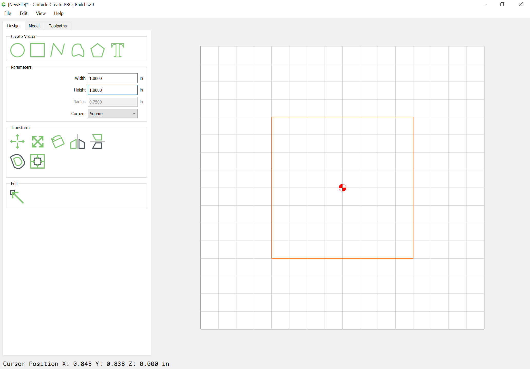
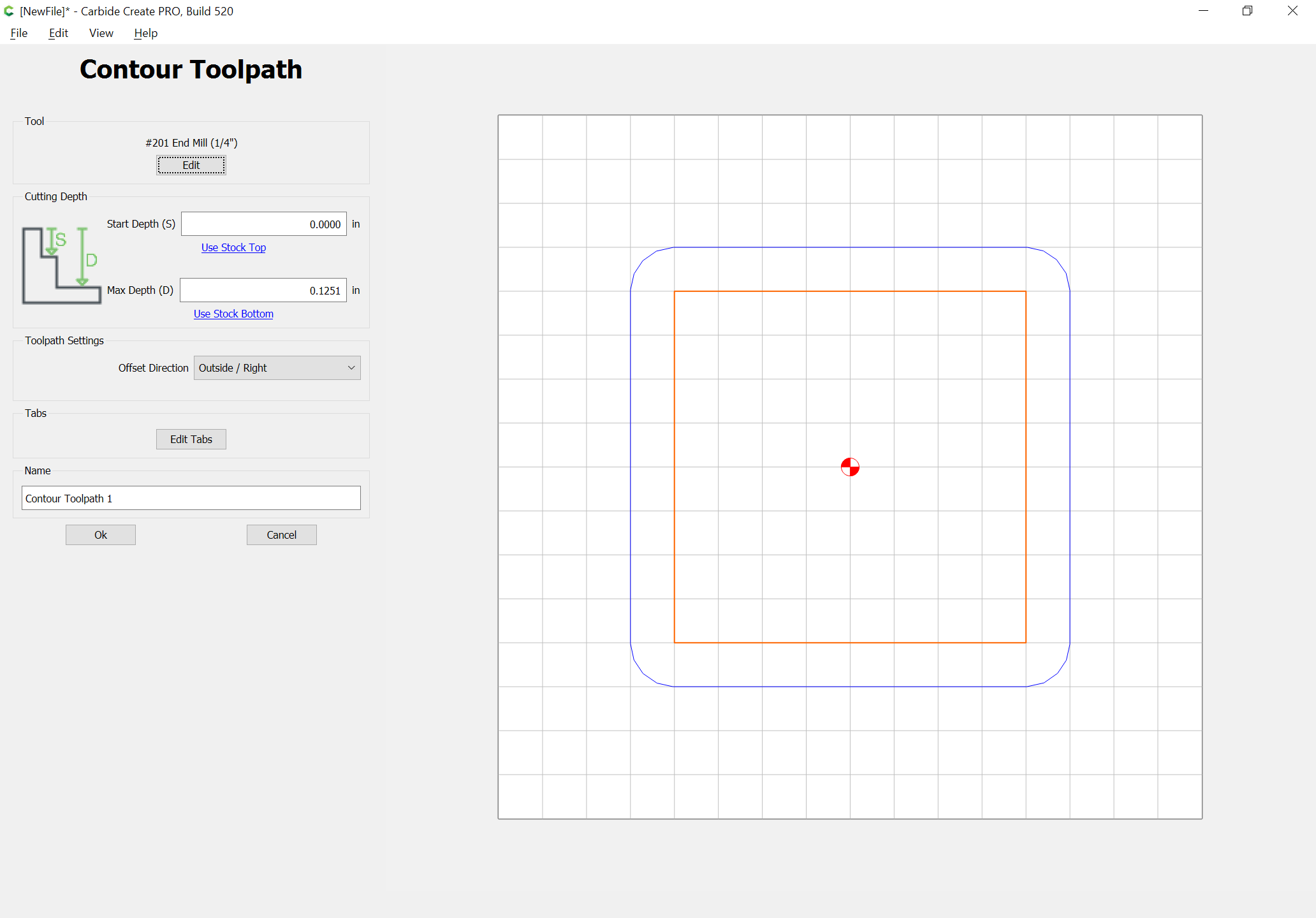
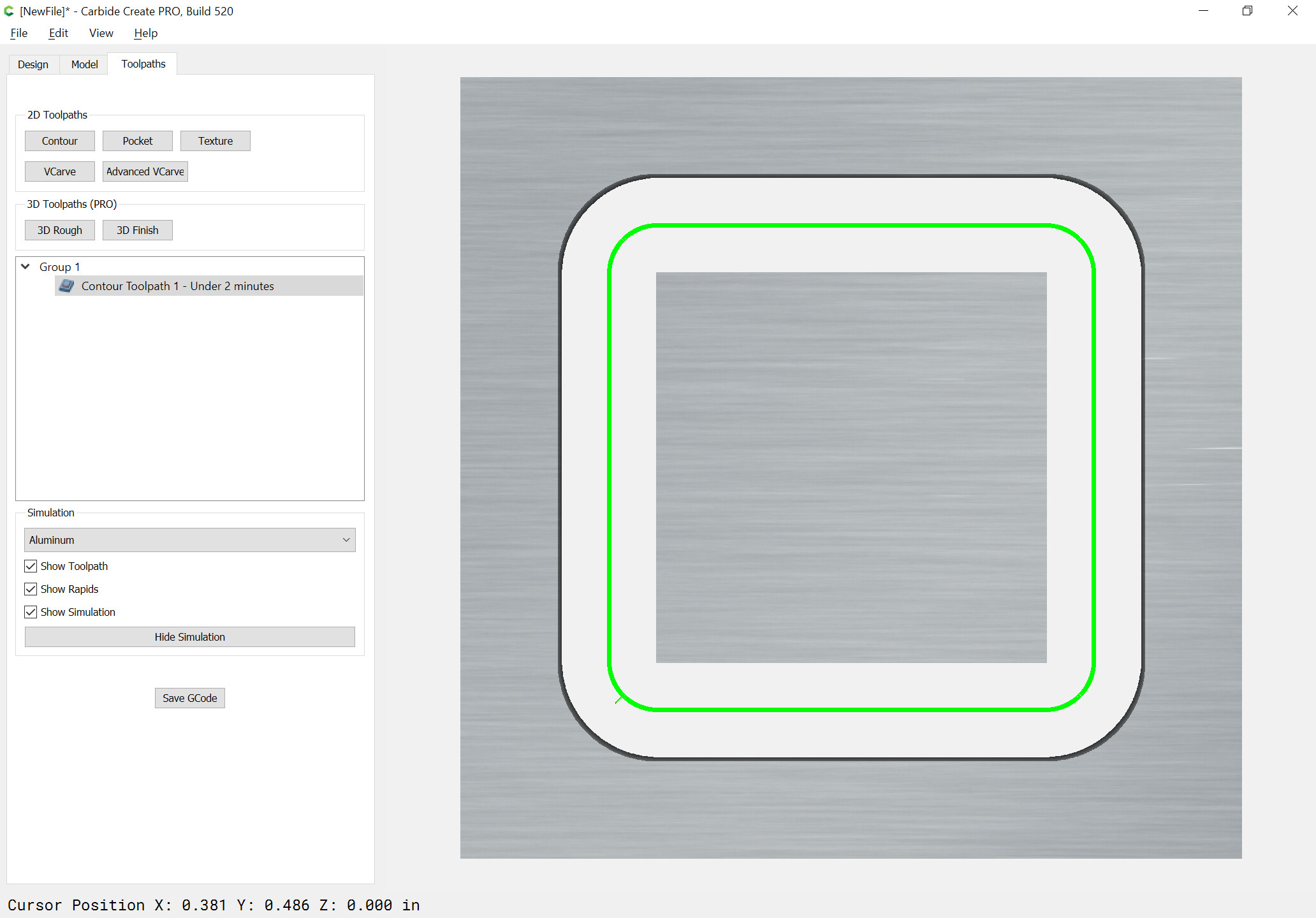
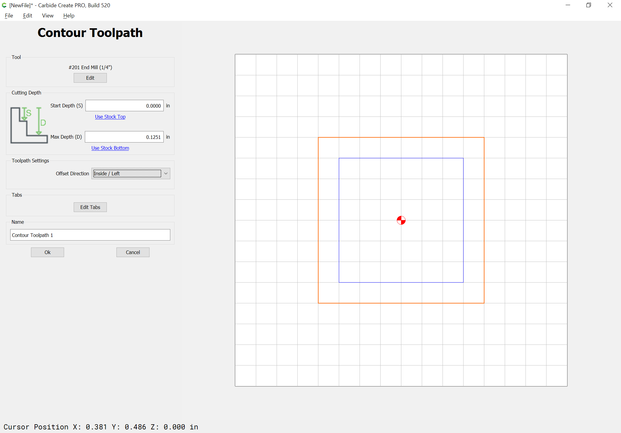
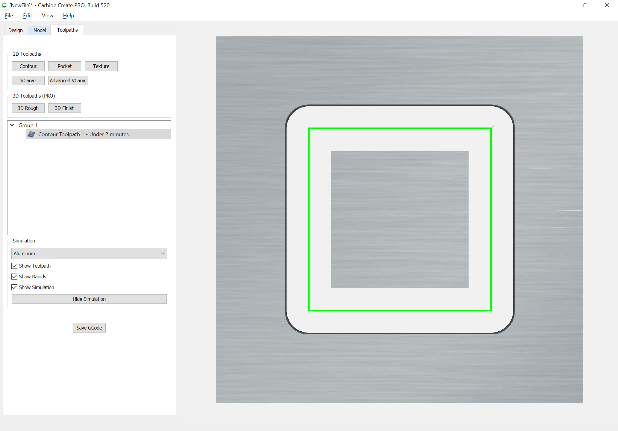
the endmill will be cutting 1/8" to the outside of the square and one will get a 1" square cut free from the material and one will have a 1.5" pocket w/ rounded corners cut out of the stock material:
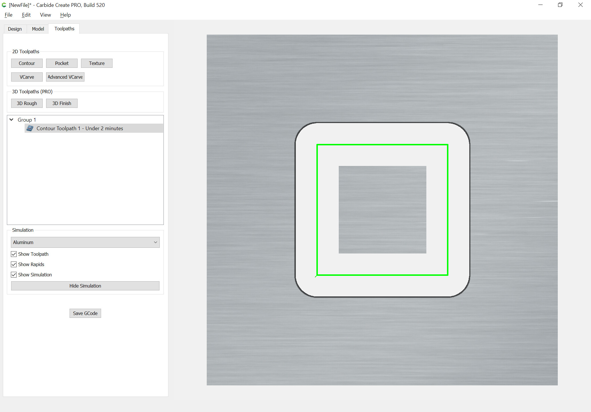
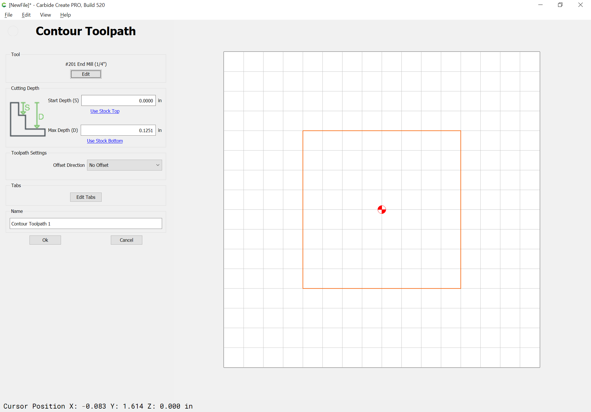
then the 1/4" endmill will be displaced to the inside by 1/8" and one will get a 1" square pocket w/ rounded corners cut out of the stock and the piece cut free will be 1/2" square:
I do have some 1/4in MDF, that might be wide enough for a test run. Nothing else comes to mind in the shop though at this moment.
Yeah, I was concerned trying to jam a .125 mill into a 3mm hole wasn’t gonna work. I can go back to the original drawing and enlarge them. All my drone hardware is 3mm, so I don’t want to get overly outsized. 0.125 is about as large as I would want to go.
If I scare up some 3mm end mills, will this file work then?
Hi Ron, welcome to the community! From the photo I don’t think this is the case, but have you leveled/surfaced your wasteboard? I might be concerned about being able to maintain .1mm depth left to hold the part, if it’s not dead flat there might be areas that are raised causing the endmill to cut all the way through the bottom of the stock and it won’t hold in place. Which leads me to my second question is there a reason you aren’t using tabs? The idea being to cut all the way through except in a few areas to hold the stock during the cut and afterward you can cut the tabs by hand leaving just a few areas of clean up on the edge of the part.
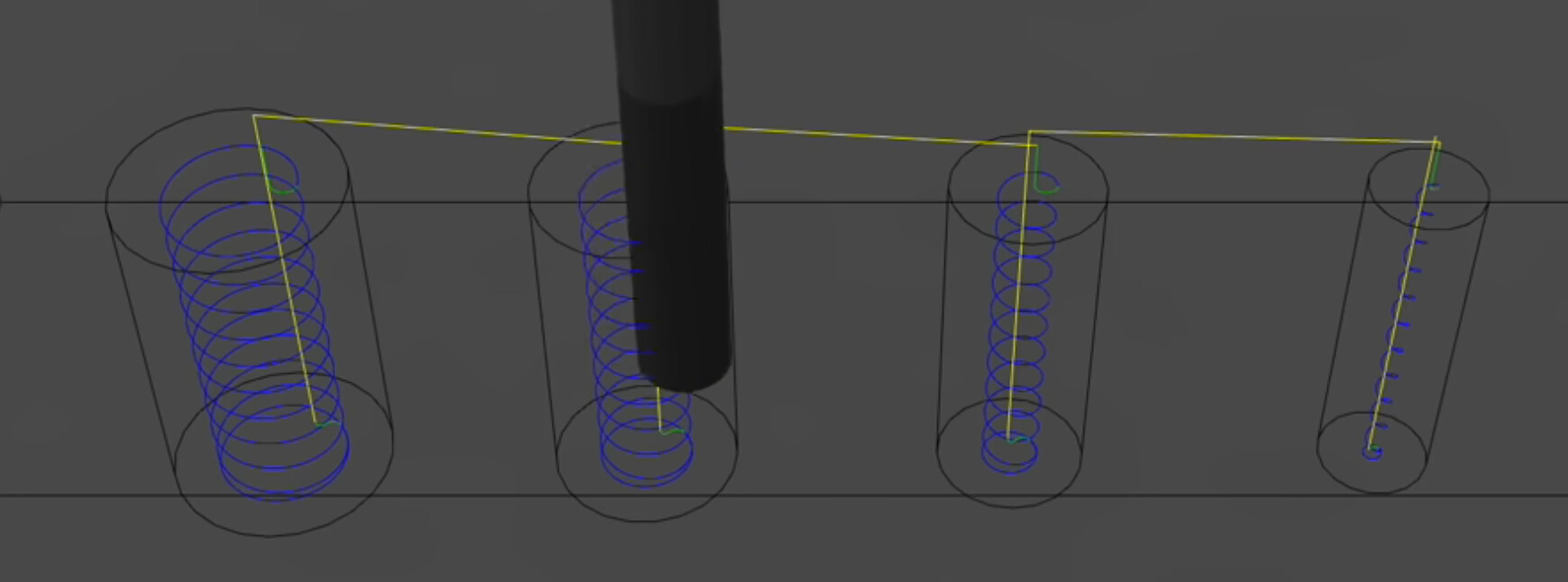
You definitely want the end mill to be smaller than the hole being cut, the reason being that end mills work best by cutting through the material horizontally so if the hole is the exact same size as the end mill, it can only be pushed down vertically. A .0625" end mill should work great. Here is a link to Winston’s video on drilling with a CNC (at 1:24 there is a great explanation).
I took a harder look at using CC last night, so re-drawing the file is in my future. Since I prefer a tighter drone motor arm screw hole, will purchase some smaller mills. I do have leftover pieces of the G10 from a previous build so have some actual material to practice my holes on.
GF - “I know nothing”, (if you’re of that age group) about “tabs”, but will watch the video. As far as leveling the waste board, I used a standard bubble level, per the assembly manual, with the understanding that’s not what you’re talking about but have seen a video where the router is used to do that, squaring the frame to the board. Give me something to do with the 1/4 mill.
I also had a thought last night about working out the tool paths. Is there a common strategy when cutting something such as my project, such as cutting the interior before the perimeter? I assume Carbide Motion steps through the tool path list from top to bottom?
Well, it wasn’t a total success or failure. I have all my fingers and the machine is in one piece, etc.
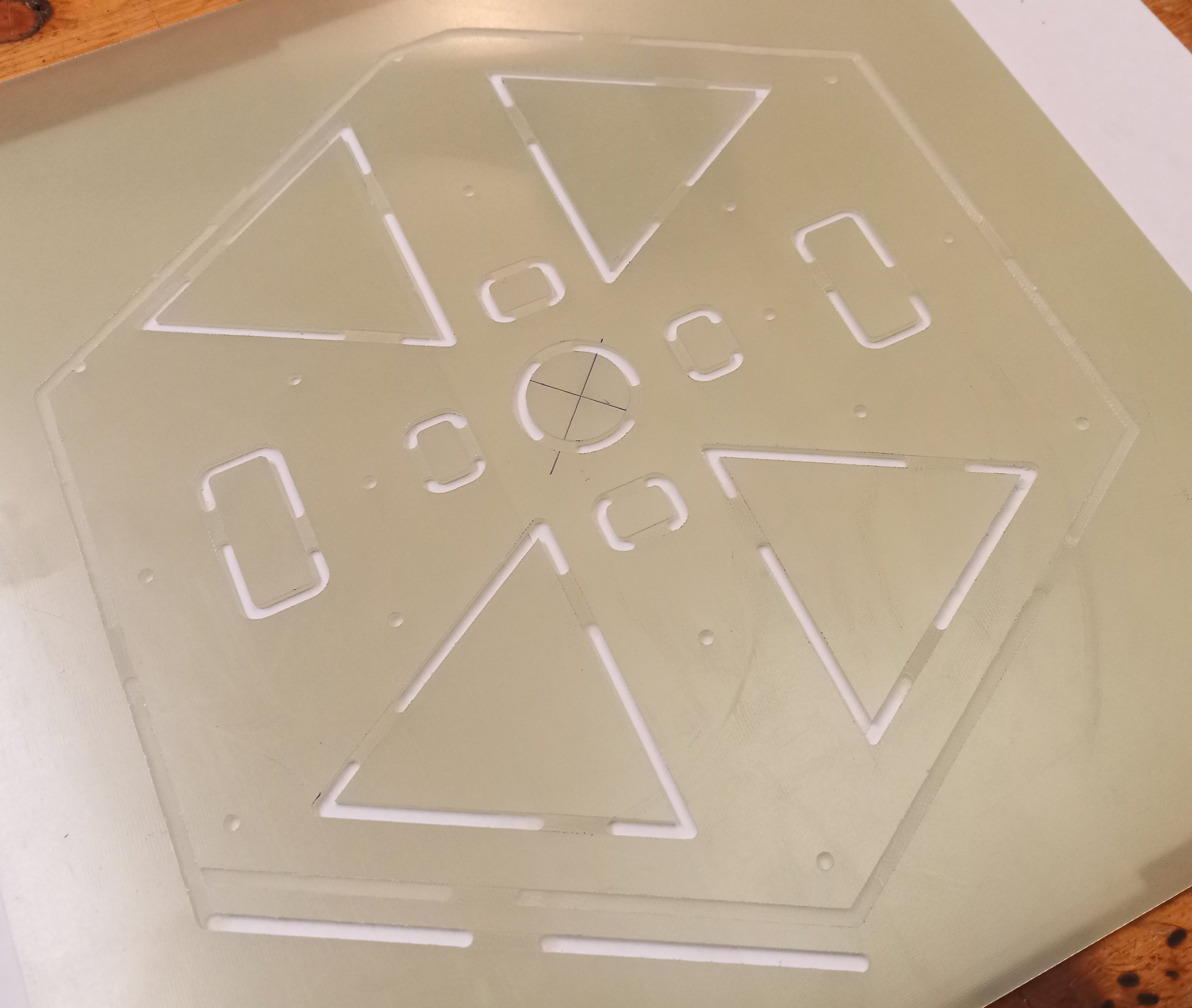
After some trial and error yesterday, I got the file to the point I thought it was gonna do the job. This morning, the attached images are what I ended up with.
After reviewing the file, my best guess to what happened is the mill came loose and as the job progressed, it cut deeper and deeper until coming free at the point along the perimeter. Need better wrenches?
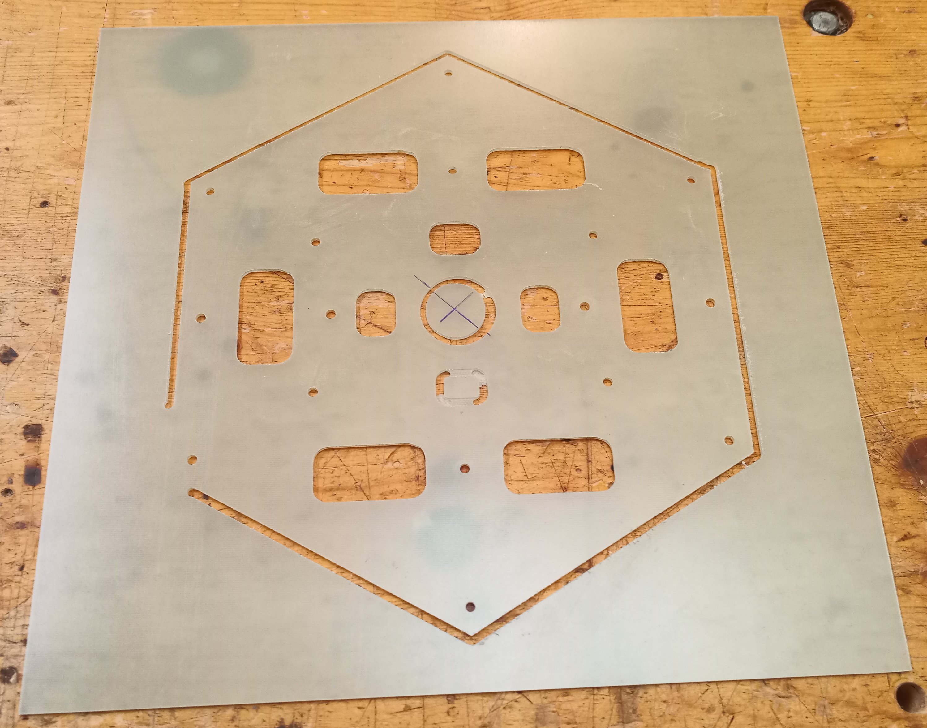
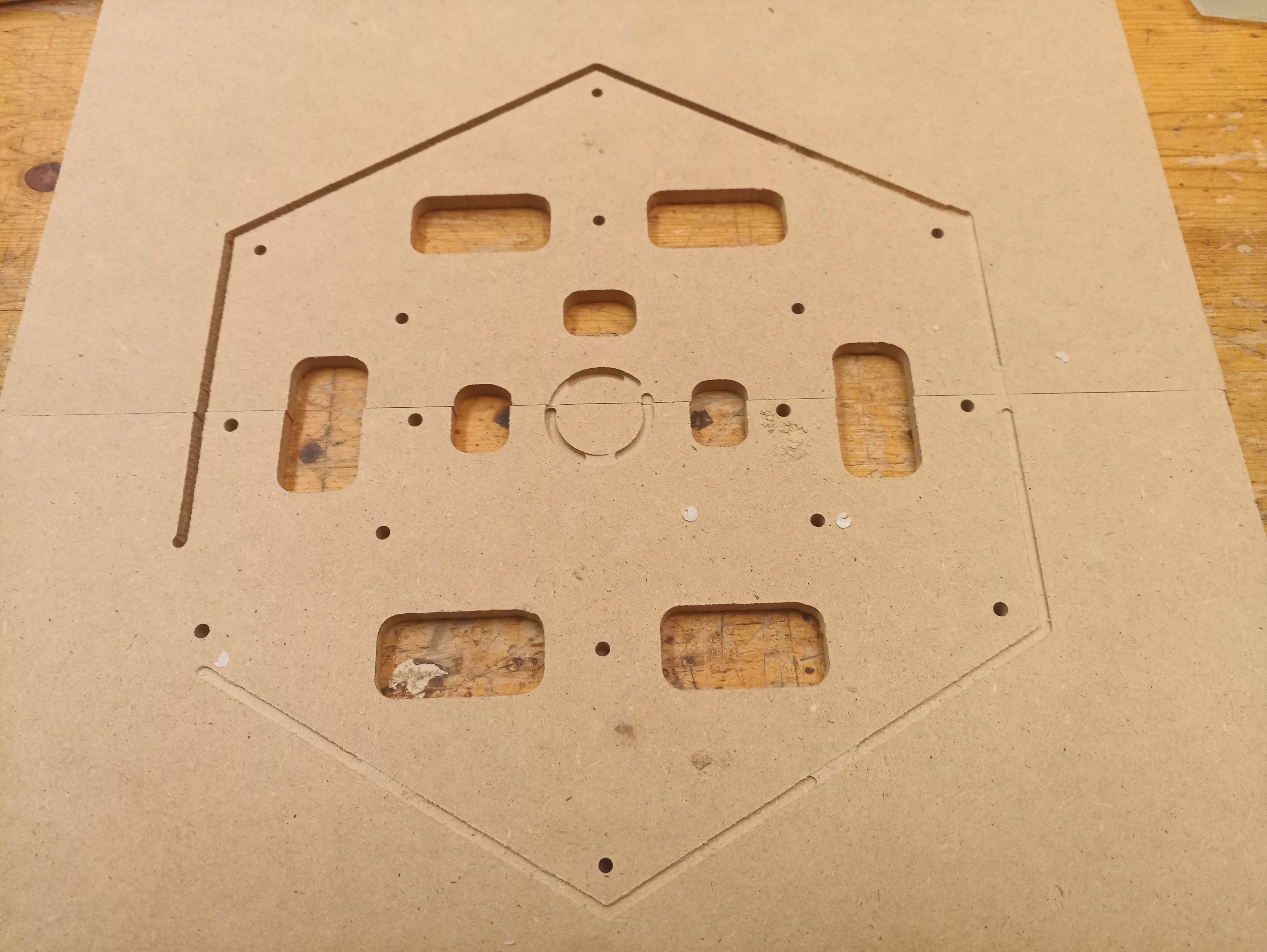
The job starts with the 5 center holes. As you can see on the waste board and G10, there’s the first cut, which looks normal in the sense the tabs are there and the cut is mostly all the way through the G10. Material is 2.3mm thick and my total depth of cut was set to 2.4mm.
Next is the center circle and while there are remnants of one tab, the cut is all the way through the G10 and now into the waste board. And down hill from there.
My initial thought, when I saw the bit cutting through to the waste board, was I had somehow screwed up the file, but I was able to pause the job at all of the cutouts and remove the G10 and waste board, 1/4in thick, to keep the job moving forward until the mill finally came loose on the perimeter cut. After I paused and re-inserted the mill and started back up, I stopped the job before the additional passes on the perimeter since the whole piece was loose at that point.
So, beyond ensuring the mill is actually tight, are they any other techniques to know the mill isn’t backing out - pause the job after a minute, look at a slippage mark on the mill shank?
OK, my lesson learned today is that the router will not cut beyond the physical boundaries of the table.
I positioned my stock a little too far aft on the table and the cut was going very well until the end. See image. I notice running into the rear Y limit also throws off the rest of the cut forward. Adjusted things forward and got a successful lower frame plate for the drone build.
I did also notice a couple of things during the cut. The compact router RPM was set at “3” on the dial, equating to 18K RPM and the feel rate was 508. The cuts had a bit of fuzz left as the router moved through the material. So for G10, if anyone has experience with it, is this normal or should the router RPM be different and same for the feed rate?
Second thing is after my encounter with the table limits, next go when I used JOG to rapidly position the router to the “center”, does this rapid positioning move the router to the center of its possible cutting area - the 16in x 16in? If so, it would be a good indication of where I should position the stock prior to securing it.
I’m getting close to a job where I need to do a bit swap. I looked around for techniques to re-zero the bit change and found various methods like a separate job file or the U shaped piece of plywood.
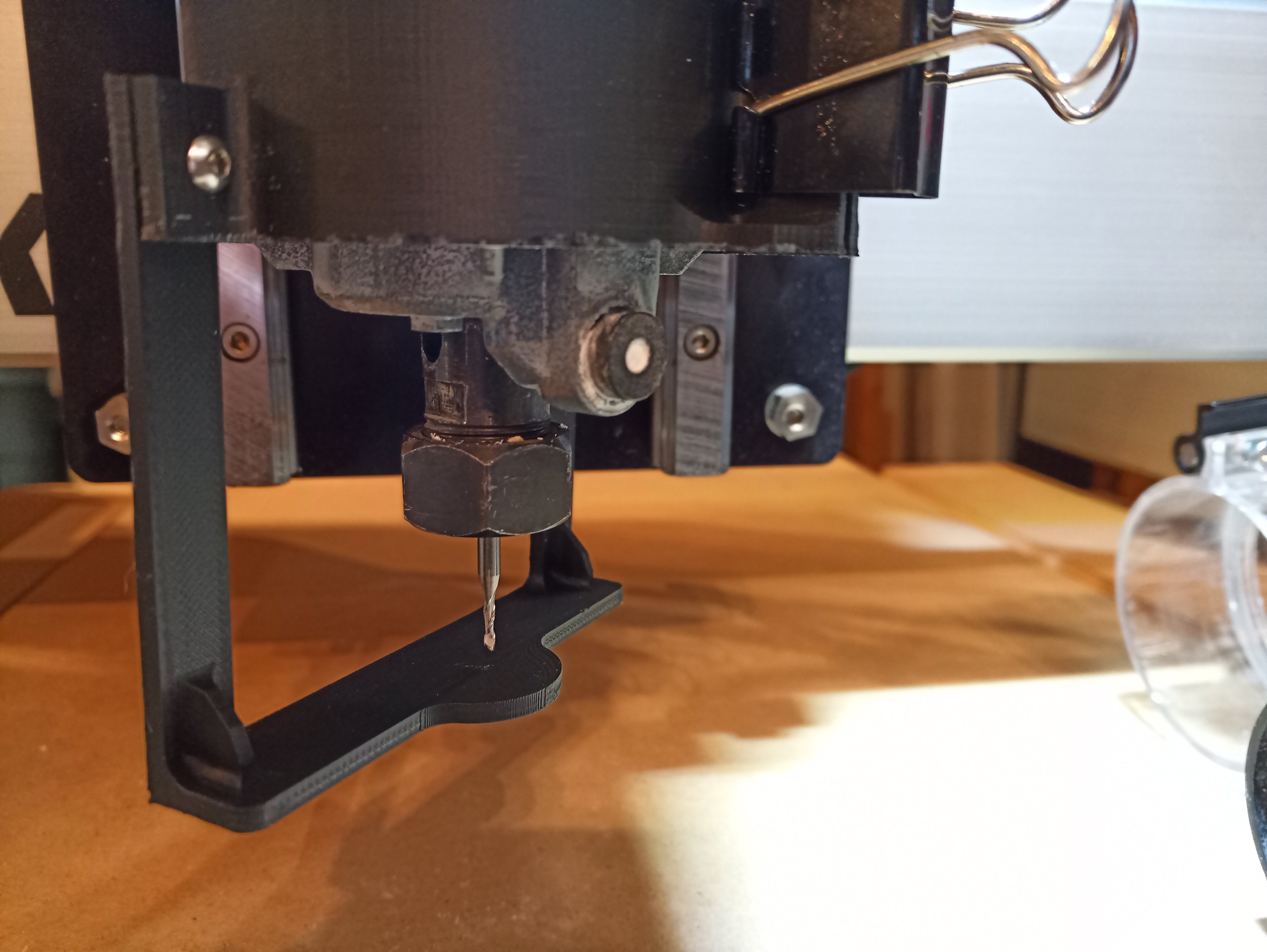
Anyway, came up with this 3D printed sleeve for the router body. My reference height is the lower edge of the cylinder aligning on the bottom edge of the router.
While I haven’t actualy done a bit change yet with this gauge, my thinking is to loosely fit the initial bit in the collet and slide the gauge up on the router body, allowing the bit end to rest on the small platform. Secure the gauge on the router - I use a “banker’s” clip and the cylinder stays put due to the router body friction.
Once the gauge is secure, and the bit end checked to ensure it’s touching the platform, tighten the collet. At bit change, remove the initial bit and repeat the process with the next bit.
During fit testing I found that the platform arms should be aligned front and back, allowing the operator to use wrenches from each side.
An STL file is attached with a router body cylinder of 65mm for the compact router. The assembly holes on the cylinder “ears” and platform arms are 3mm.
As always, YMMV, but hopefully someone can make use of it.
My suggestion based on similar things is push the endmill up, then let it drop, then tighten — that seems the most consistent.
I would suggest setting up the arms w/ labeled rebates to match the different shaft lengths of different endmills (or make one for each length of endmill you use).
Yeah, this thing is best with the shorter mills - I’m using the 1/8th and 1/16th. I sized everything for those mills. The 1/4, being longer, would cause the cylinder to be lower on the router body necessitating an alignment mark.