Answers are needed... (For Safety & Reliability)

Hi guys!

If you read my final post in my previous thread, something went wanky on me when I decided to create my wasteboard.

Here is the image of the bottom side of my MDF…

IMG_20180728_204531581

I will also upload the 4 files that were used to create my wasteboard. The 4th was just to drop my profiles from 0.065" to 0.085", and that went super smooth!, so there is no need to review that file, but I will upload it nevertheless.

I will upload the gcode files once I get to the shop, in about an hour or so. Have to walk the Puppy!

But for now, I will share that the first pass was that column I’d call 1.75. When I saw this.I hit the pause because it just seemed to be greater than 2" from 0,0,0. I then stopped the session and restarted it. That is where the pockets just north of the final ones started. Once again, I was at the ready to hit the pause, but I just let it play through. It started the second row correctly, and when it came to drill the holes, it hit everyone on the mark.

I need to understand just what happened at the beginning of this job!

For my sake and the safety of my tools in use.
Always simulate — in addition to the built in previewer in Carbide Create, Camotics works well:

https://camotics.org/

If the machine’s behavior doesn’t match what is simulated, then there are only a couple of possibilities:

1 Like

7568.zip (83.9 KB)

7568 is my S/N.

Bottom Wasteboard.gcode is the problem child. It was the file to falter in both Column 1 attempts.

Bottom Wasteboard2.gcode is where I tweaked something (sorry did not write it down).

Recess2.gcode was for… Totally forget now.

Bottom T-Nut… was to deepen the 0.065" to 0.085" which worked out perfectly to sink the material of the T-Nuts under the plane of the MDF.

Now I understand that yes I used 1/2" MDF for my wastboard (I have 3/4" on hand, and will fabricate a duplicate soon enough), I just want to ensure the Funky mind of my gcode is caught and dealt with accordingly, and that I am able to understand what went wrong. Was my computer using too many resources at the time, and it failed to multi-task as expected?

I shall wait for our resident experts to review my 4 files just to ensure all is good with the code of the files.

Wasting MDF is one thing, wasting OAK, Padauk, Wange, Zebrawood, or the other fine woods I have here that I use for my Pen Making is nothing short of not acceptable to waste away. Mikey just don’t have that kind of money floating around here… LOL.

Thanks for all who assist me in this next phase.

Just think… Making my hold-downs comes next once I am given the green light on this issue.

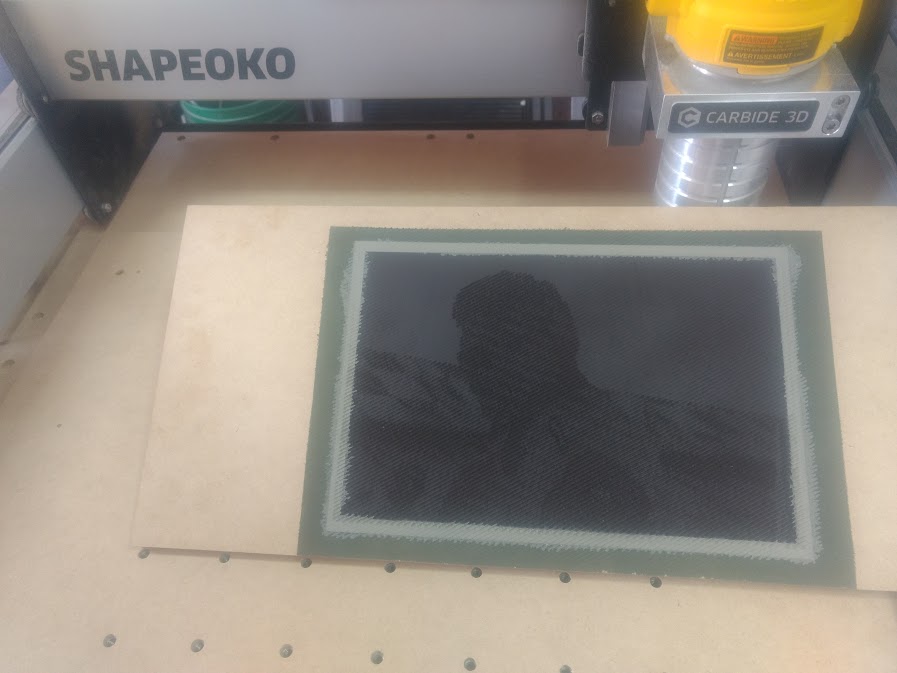
Now, I would like to share that this wasteboard is the 4th project 7568 has cut. I have cut 3 PVC files (first two were with too much detail, and cunked out the majority of the 0.15" or 0.2" of Baltic Birch Ply with my Chinese 30 Deg Pencil Bit.). The 3rd popped my eyes when I coated it with a layer of Flat Dark Camo Paint! WOW… Sure I screwed it up by trying to layer in 2 other colours of Camo into the pic. The image was just a pure test, as I could not locate the NASCAR 2015 Logo, which was to be placed in the Upper Right corner.

So, 7568 sure seems to be working as far as working the gcode being sent to it.

An extension to having troubles cutting low is the mechanical limitations of the Z-axis — it’s a long reach down, esp. w/ the new, shorter (but much stiffer) endplate, so you should mount the router as low as it will go (consider flipping the spindle adapter over if using a Makita as @wmoy has suggested) and if need be, temporarily remove one spring.

1 Like

I don’t think I have a height issue, as I have (at present) a 1/2" MDF over the stock wasteboard. I might be able to loosen the hold down screws on my DeWalt to see if I could drop it 1/8", but I don’t see where 1/8" would resolve any issue at present.

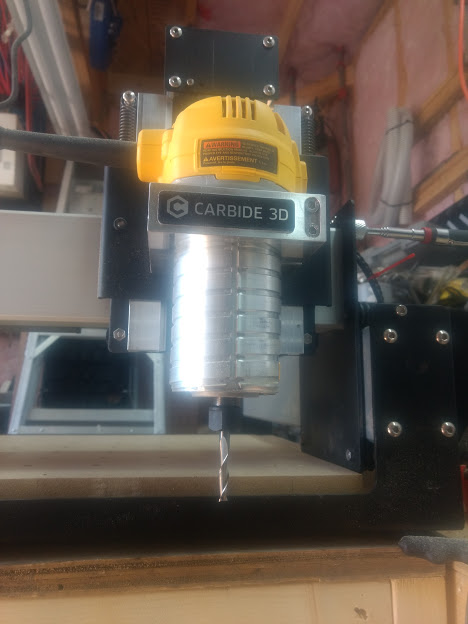
BTW, in the included image, one can make out the 611 hanging in the mount. :wink:
Oh…

My router sure can get into low lying troubles real fast if I’m not on top of things here!

1 Like

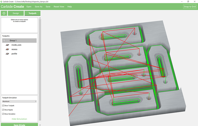
I would like to note that in Carbide Create, by downloading the clamp file and selecting Pine, then hit Simulate, an empty small pop-up flashes for a sec or 2, disappears and then the project disappears from sight, leaving an empty preview.

I can easily share screenshots if you like?..

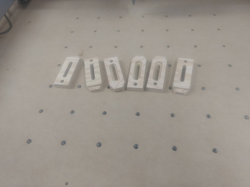
I was able to cut 6 clamps and channel a cut / lip on my table saw at the ends for extra hold down power.

Baby steps…

1 Like

Which clamp file are you having difficulty with?

The one from: http://docs.carbide3d.com/tutorials/shapeoko-clamps/

http://docs.carbide3d.com/tutorials/shapeoko-clamps/shapeoko_clamps.zip

previews as:

1 Like

It was the zip file. 2 files were zipped together. *.c2d & *.nc

I never saw green lines. Red & Blue.

In Carbide Create 316 you can show or hide the green lines using the checkbox “Show Toolpath”.

Thank you @WillAdams for this.

I’m in the house right now nursing a headache… until one is comfortable with the whole concept of CNC, one is always waiting/anticipating for something to go BAD real fast! So one must have the mouse ready to hit the Pause ASAP! Evaluate the situation and choose either to Stop or Resume the game. That in itself tosses a bit of stress into the equation. Or in my case, a couple of Liquid Advils!

Yeah, CNC does tend toward the nerve-wracking — the great thing about it is that the machine will cut a file without error, and perfect repetition, when everything is set up correctly and working well — the awful thing about CNC is that it will only cut a file correctly when everything is set up without a single flaw, and only so long as nothing goes wrong, and the machine doesn’t have sensors or the ability to pause and adjust that one has in hand-work (and it’s much noisier than handwork).

2 Likes

As an aside, this new end plate is a real problem with Kress spindles. I’ve had to add a waste board several inches thick just so I don’t keep dropping the spindle off the bottom of the Z axis. It’s really not good. :frowning:

Yeah, I have to confess that I’m still using the original endplate on my XL — it makes things tight sometimes, but I’ve got a 65mm mount I bought off eBay which I had to drill and tap to fit (you can see it in: https://cutrocket.com/p/5a6bbc6cdbea4/ — second photo)

My suggestion would be to have a sheet metal shop make a suitable length / width blank w/ bent edges which has the horizontal dimensions and form of the new plate, but the height of the original.

I’ve been meaning to check and see if there’s some stock extrusion or a formed steel product which would be suitable.

1 Like

Hmmm, my recent adventures in cutting thin stainless sheet metal have worked out ok. I might experiment with something a bit thicker. For the bending part, it turns out pretty accurate results can be had with the careful application of percussive therapy. eg whack-it-with-a-hammer-while-held-in-a-vice. :slight_smile:

1 Like

This topic was automatically closed 30 days after the last reply. New replies are no longer allowed.