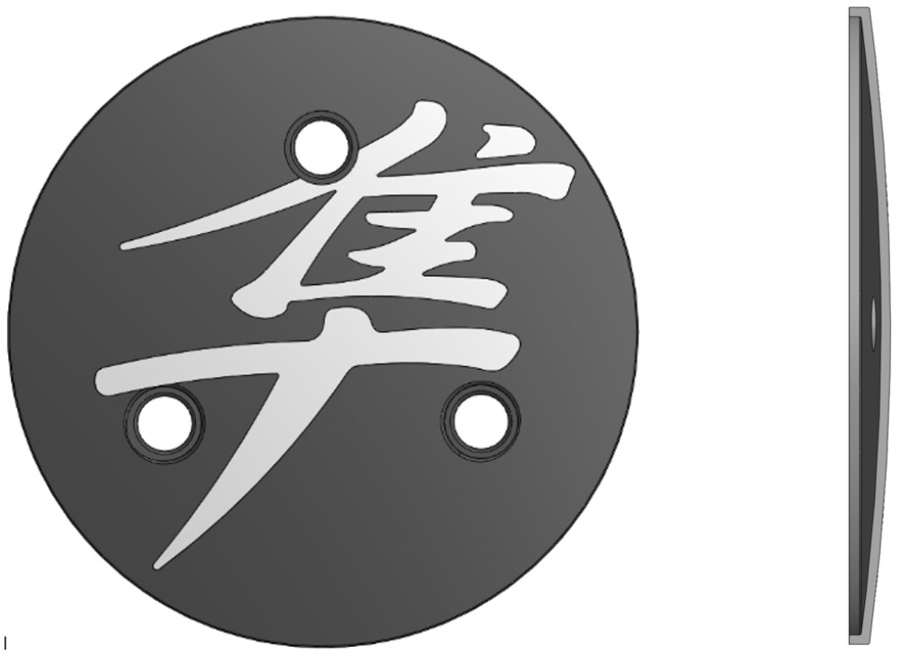
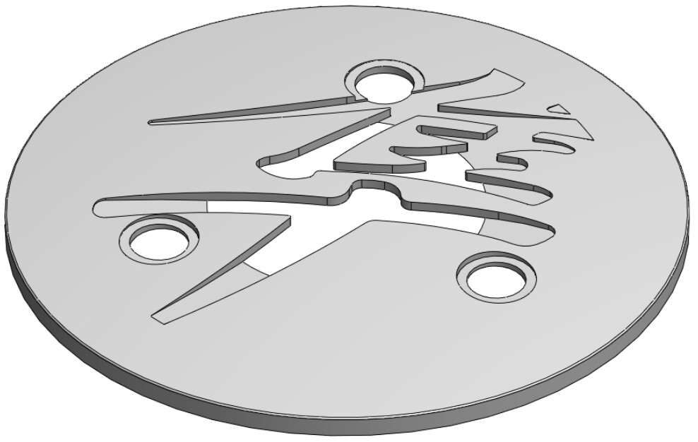
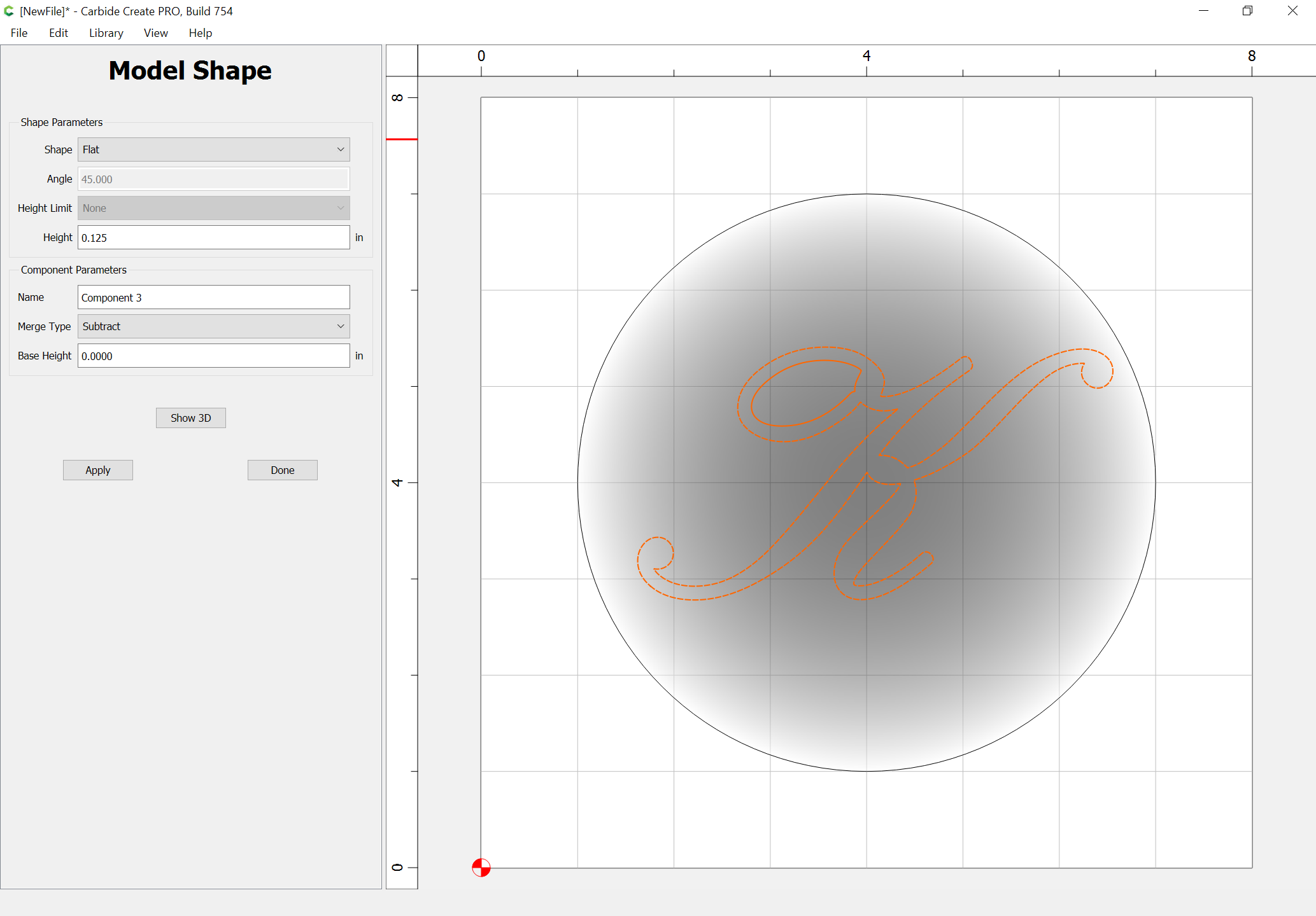
I’m working on a new project where I hope to engrave a Japanese character into a cast aluminum side cover plate from a motorcycle engine, as shown in the photo. I took measurements from the plate and modeled it in SolidWorks, then added the Japanese character. At first I thought this would be a quick easy process, as I was just going to cut the character out as a simple 2D pocket using Carbide Create (standard, I don’t have the Pro version). As seen in the images, the plate is domed, which means the cut would be deep near the middle of the part and taper off to shallow near the edges, which would be fine. It looks like this won’t work, however, because the part is not sufficiently thick and/or too small in (spherical) radius to pull this off. If I make the cut deep enough to get the whole symbol I’ll be cutting all the way through the part near the center, as shown below. One option here is to scale the symbol down until that’s not the case, but I’d rather keep it big.
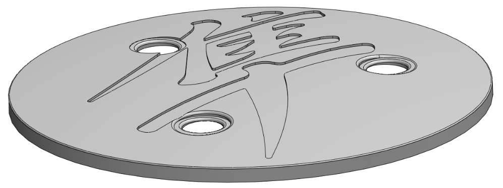
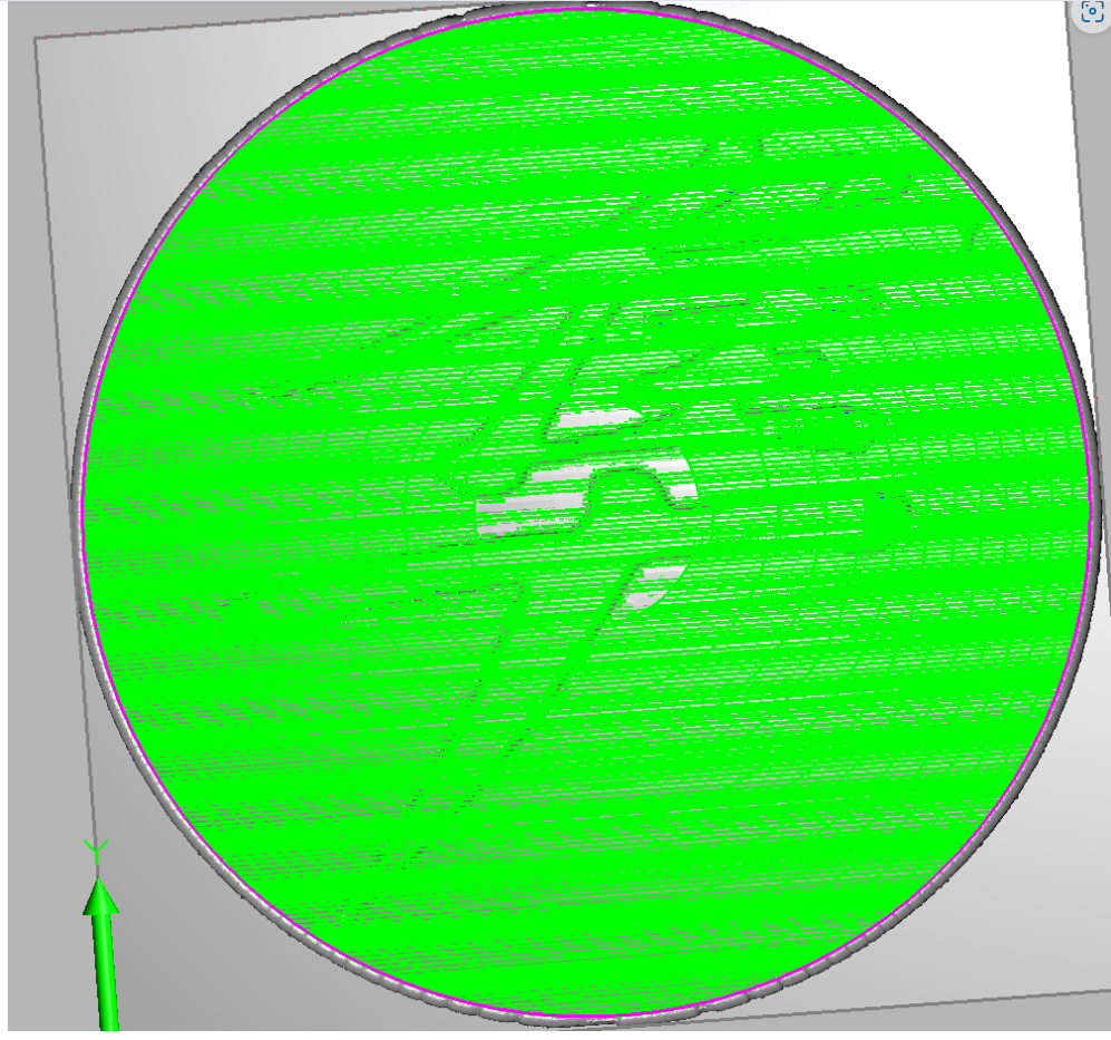
The second approach I have considered is to re-do the cut as a constant-depth spherical cut. This would be the preferable approach. In SolidWorks I modeled the symbol cut as a .020 deep wrap cut (a “debossment”, as SolidWorks calls it), as shown in the image. That looked good so next I had a go at setting up a toolpath in MeshCAM Pro (using a 1.5mm cutter). From what I could see it is not doable without cutting the entire top surface of the part (see bottom image), whereas I only want to cut the symbol.
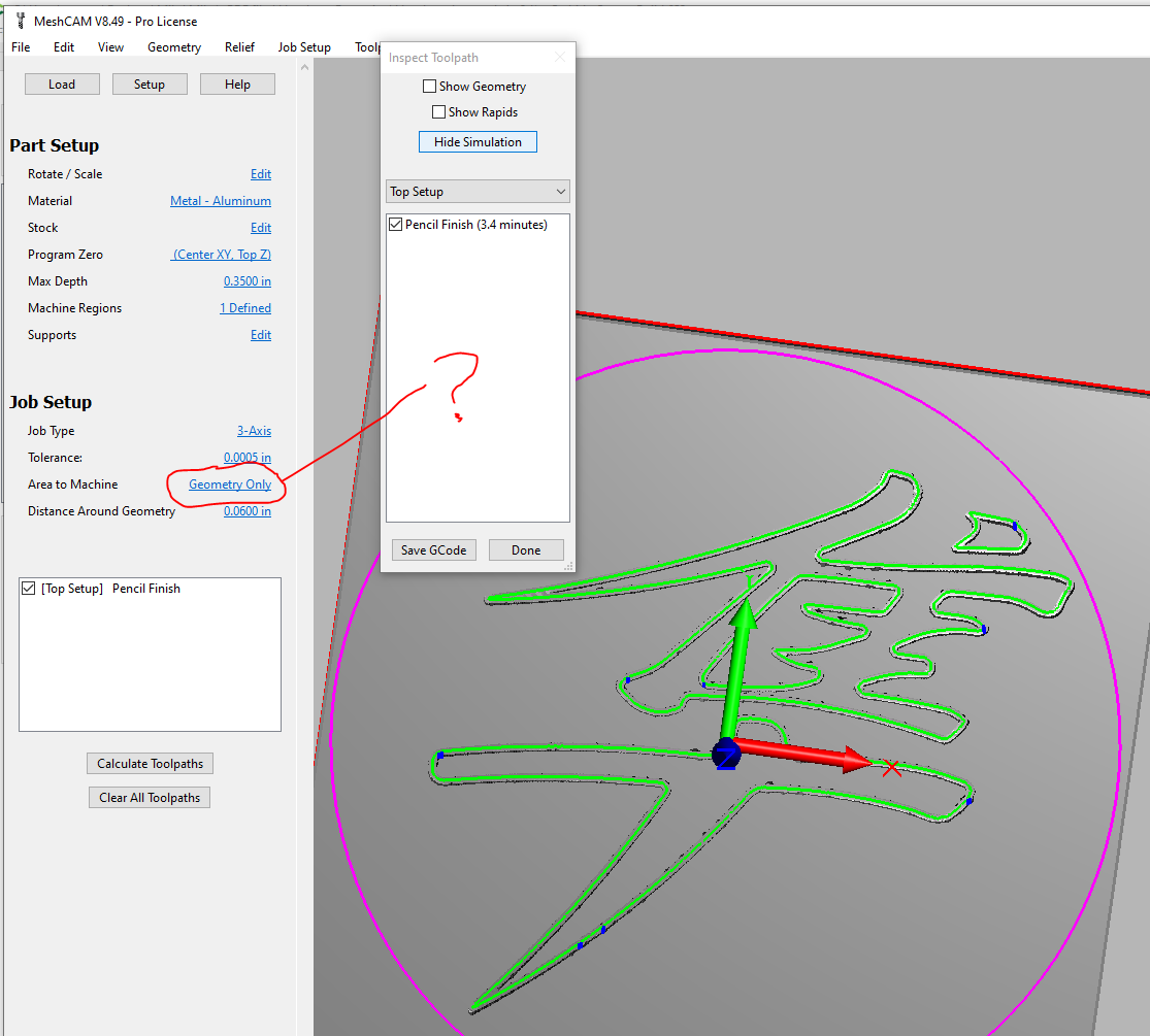
I inquired with MeshCAM on this, and the reply was to try a Pencil cut toolpath. That “sort of” works, in that it will do the spherical cut, but it only cuts the outline of the character, not the full pocket. I’m shooting for the whole pocket. I didn’t hear back from them on a follow-up inquiry. There’s a crowd of smart people on this forum though, so I figured I would extend my inquiry here. One question is, might Carbide Create Pro be of some help here?
Yes, if you can model the dome, then subtract the pocket from it, then use the geometry to limit the 3D toolpaths to what you want, that should cut — the same technique should work in MeshCAM though.
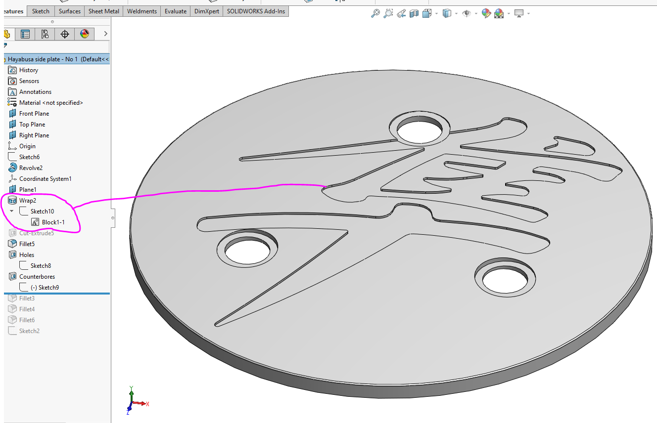
By “subtract the pocket from it” do you mean literally, in which case I feel like I’ve already done that in my SolidWorks model, or do you mean in the sense of the SolidWorks model tree - as in, subtract it from the model tree? The image attached show the SolidWorks model & model tree, with the Wrap cut (“debossment”) circled. I can’t just extract that feature on its own though, because it depends on the dome shape to exist. To create it I sketched the Japanese character on a plane and then I had to select the dome as the surface onto which I wanted to wrap it.
When you say, “then use the geometry to limit the 3D toolpaths to what you want”, where do I do this? In Carbide Create? In MeshCAM? I see in MeshCAM (bottom image) the option to set “Area to Machine” to “Geometry Only”, which I use regularly. I guess I just don’t understand how & where to go about it.
Not sure how it works in MeshCam, but in CC you can import the curves for the Japanese character & use them as a boundary for the 3D cuts, so it’s not cutting the area outside, or your top spherical surface.
Hey Tod! You helped me before - on that turntable project, as you may recall. That’s working well, by the way - now that I upgraded my turntable motor.
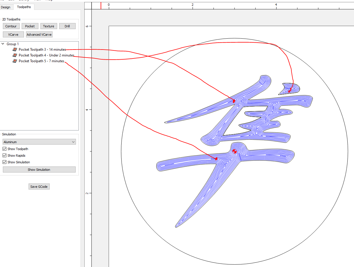
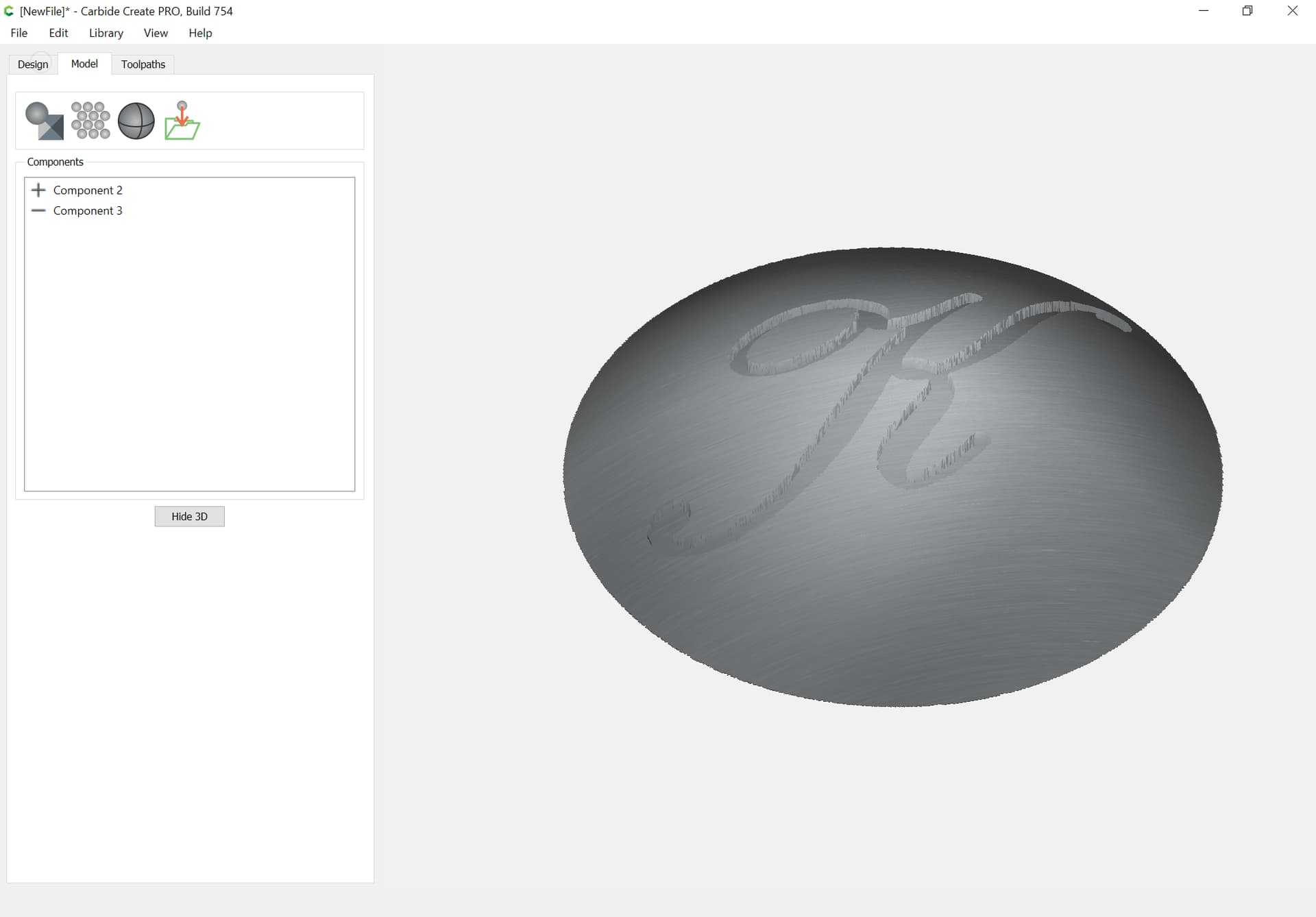
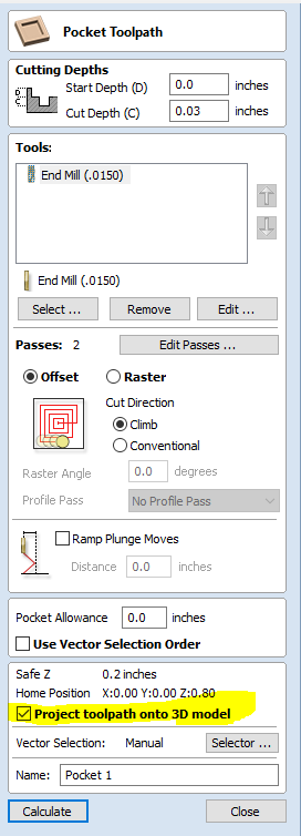
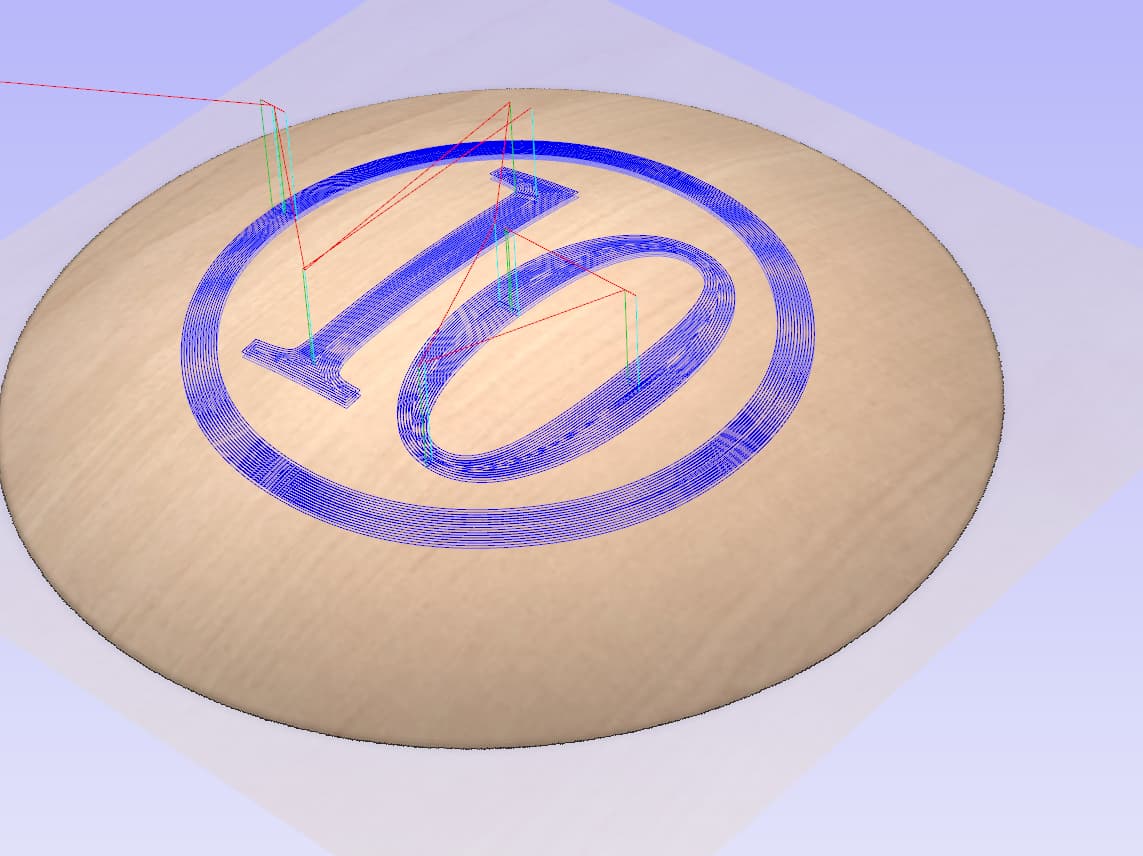
In any case, as for this Japanese character cut, I believe I tried what you are suggesting. I brought the shape into CC, and then made three pocket toolpaths, as shown below. But that gives me a planar cut (deep near the middle of the part, shallow near the edges, as shown in one of the images in my original post above). The dome is a shell only about .100 thick, so to fit the whole character I’ll cut right through it in the middle zone, as shown in that same image. So I’m trying to achieve a constant-depth spherical cut instead. I can’t see how to get CC to do that, which is what spurred me to try MeshCAM.
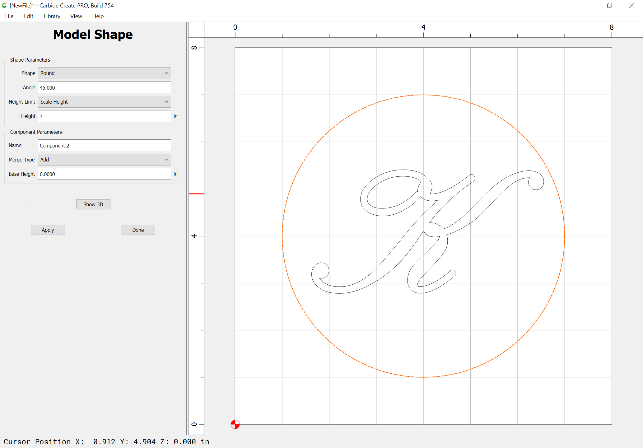
CC Pro has rough & finish 3D cuts. Rough is a lace / z-level mixed cut. Finish is only a lace/zig-zag/raster pattern. It works well on wood, but I think I would opt for something with a bit more control for metal.
Glad to hear the turntable is working out. For giggles I chucked up a piece of walnut in my dremel lathe mounted to the HDM, and programmed a lathe type path in XY on the centerline of the lathe.
Came out pretty nice. I had to play with the feeds & speed quite a bit to get the ‘sweet spot’.
Very cool! That’s a nice capability to have. Is that thing a fish conker? You’re a fisherman, as I recall from an e-mail conv last summer. Now that you’ve worked that out I bet you’ll think of plenty of uses for it. I have for my turntable.
As for this spherical cut matter, I’ll look into CC Pro, especially in that Will Adams has now also referenced it. I know you don’t have MeshCAM, but it surprises me that it (even the Pro version, which I have) doesn’t seem to handle this type of cut. When you say you’d “opt for something with a bit more control” do you have anything in particular in mind? Fusion 360, maybe? I don’t have it, but many people doing tricky shapes seem to use it.
No, it’s small. Like a pen blank. But a fish bat is a good idea!
I use NX when I’m not using CC. I have the control to drive the tool however I want to. If I want to do an inward follow periphery pocket but follow the 3D pocket bottom, I can. Or I can do the whole thing as a Z-Level cut where it traces passed at constant depths, then moves a small amount to the next depth. I can do a spiral cut from the center, or reverse it to start on the outside & spiral in.
In CC, it’s only a Lace/Raster/Zig-zag cut. Teh only thing you can change is the angle.
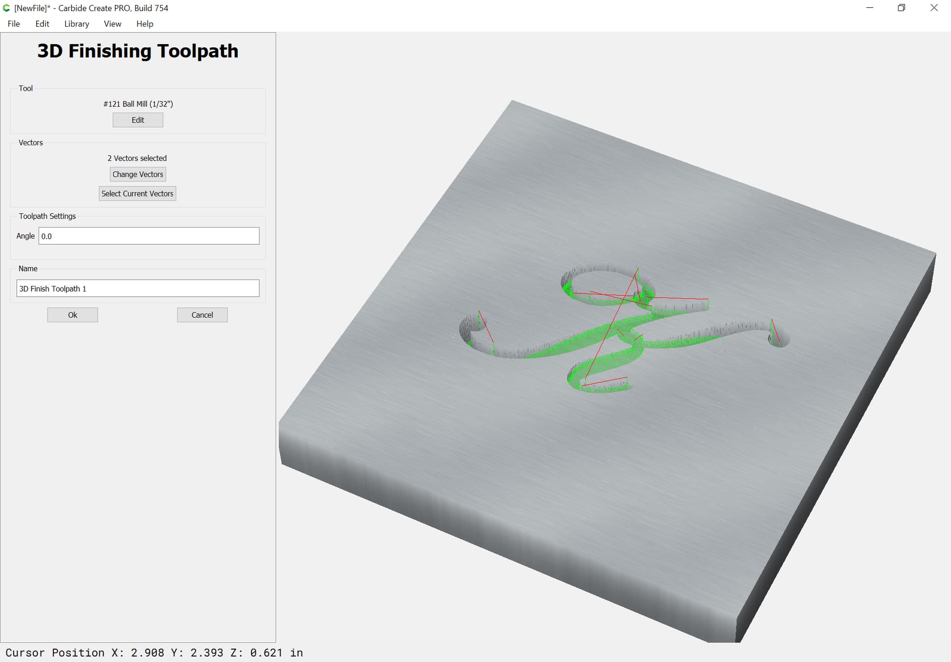
Thanks for all that, Will. I’ll look into Carbide Create Pro now. But allow me to ask this - does my SolidWorks model do me any good in this case? That is, do I start somehow by importing my SW model, or is the modeling done in CC Pro? Looking through your screenshots it’s not clear where the spherical/dome shape is introduced. The fact that the finishing cut (your last screenshot) is shown as flat (non-spherical) is a head-scratcher too. As I mentioned to Tod, it surprises me MeshCAM Pro doesn’t seem to handle this type of cut. In any case, I think I’ll try the Trial offer for CC Pro and see how I like it. Thanks again for your help.
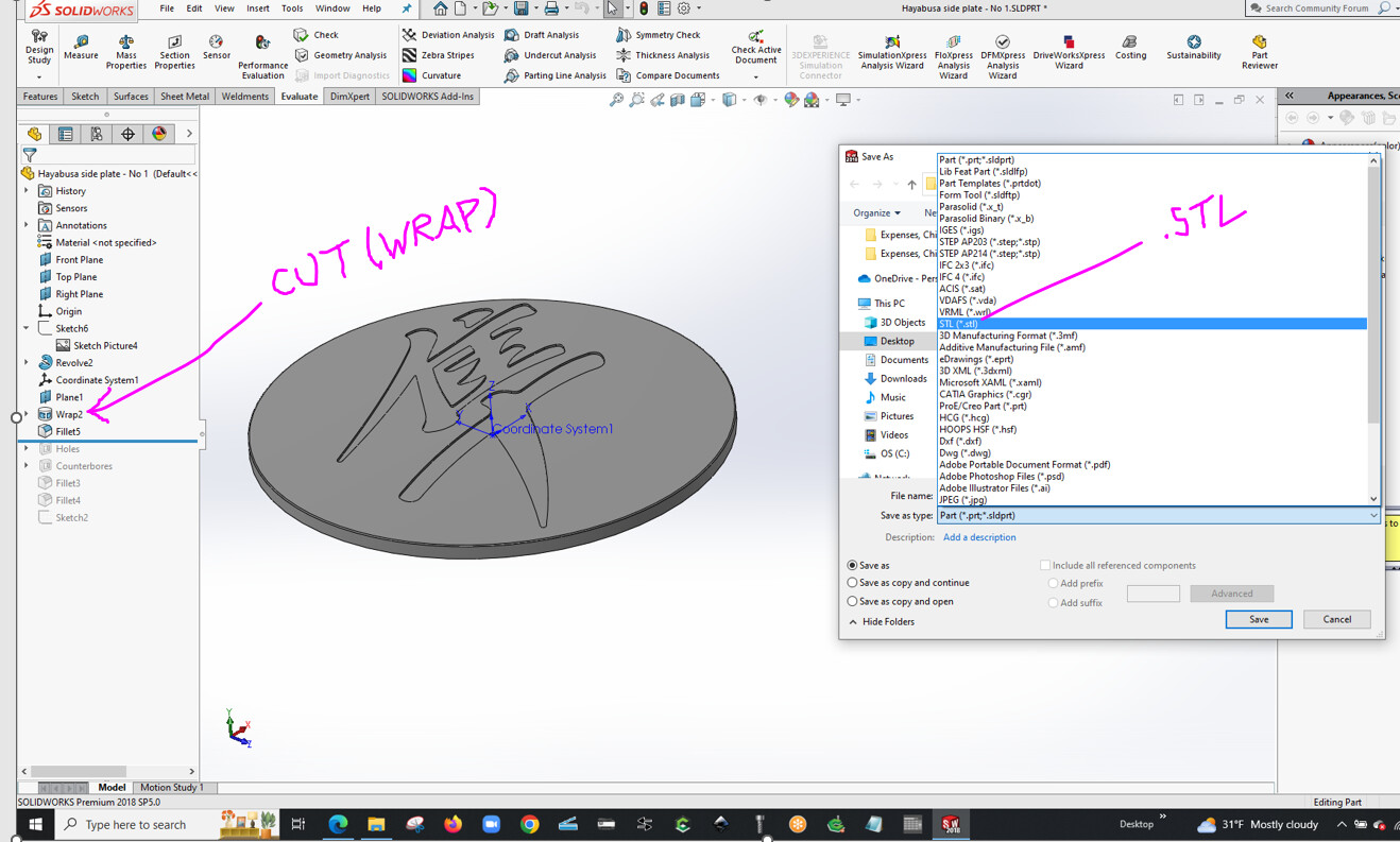
If you have the SolidWorks model, to work as I was showing, you would model the lettering incised into the dome, export only that as an STL, import the STL into Carbide Create, then use the geometry surrounding the lettering to limit where the cut happens.
As far as I can see, there is no means of exporting only part (or only a particular feature) of a SW model as an .STL. It seems to be all or nothing, as shown in the image below.
I can save just the sketch of the Japanese character, but not any feature that was made from it. That’s what I did to create those simple 2D toolpaths in Standard CC in the earlier images I included above.
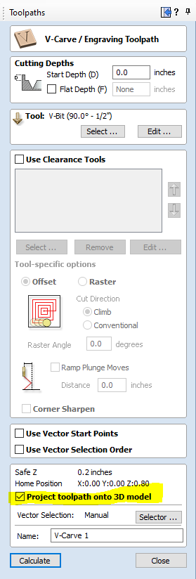
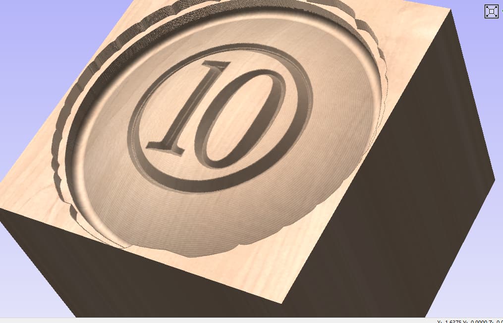
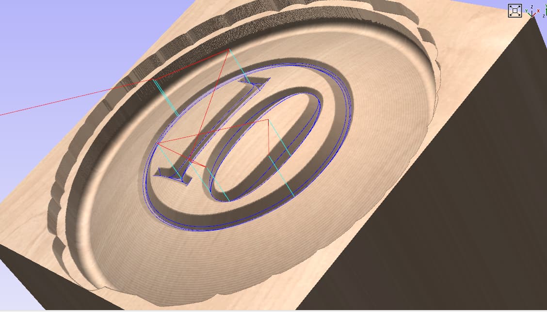
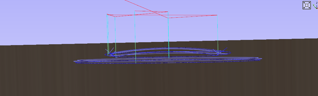
I have SolidWorks and Vectric V-Carve. If you send me the SLDPRT or STL, I can open it in V-Carve and generate a tool path just for the character with whatever V-Carve bit you want.
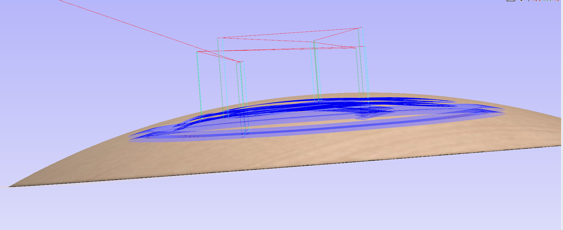
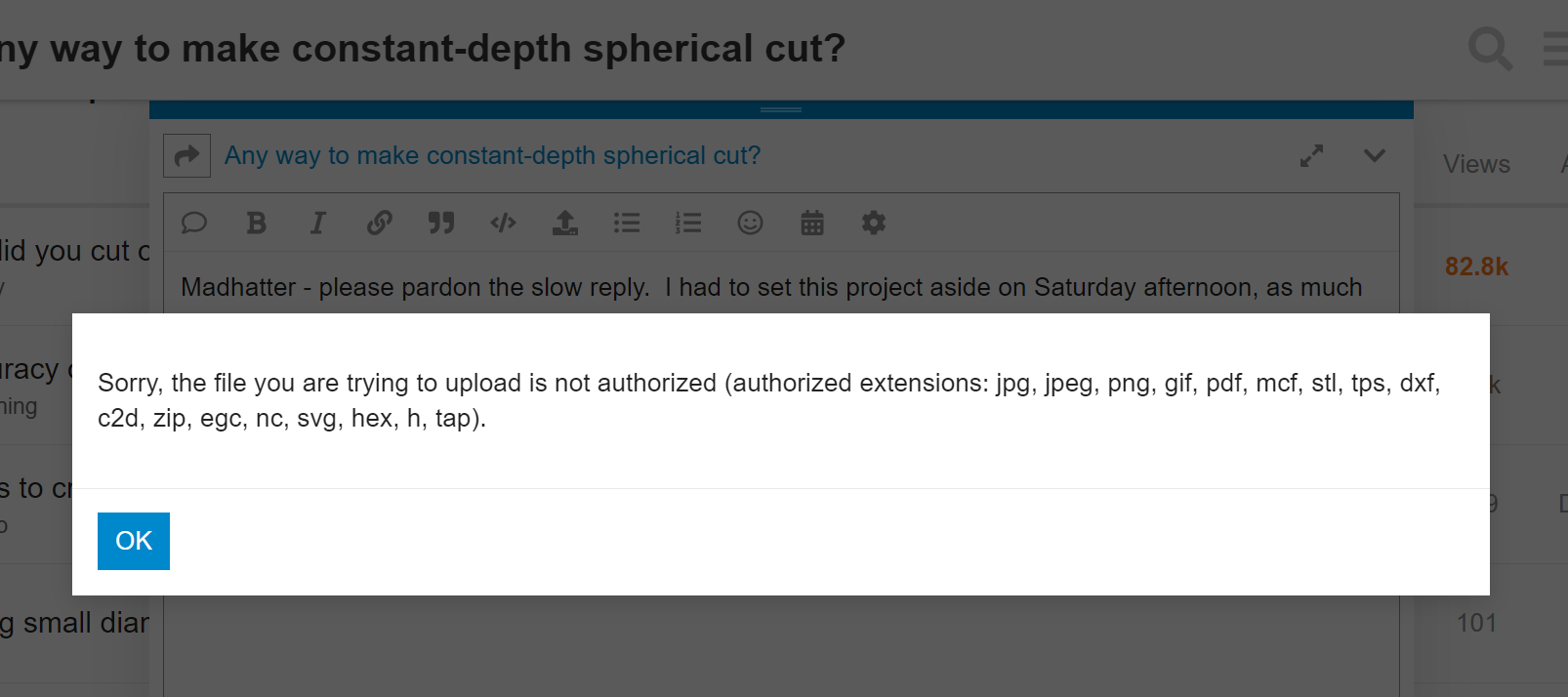
MadHatter - please pardon the slow reply. I had to set this project aside on Saturday afternoon, as much as wanted to mess with it. Very cool V-Carve capabilities! I’ve never looked into it. Wow. I thought MeshCAM would be able to do such a thing, as it seems like it must come up regularly in this CNC router world. In any case, it’s very neighborly to offer to help me, and I’ll take you up on it. Please see my SolidWorks model attached. It’s in SolidWorks 2018, by the way. Will that work for you? Note that in my model the character cut-out has sharp bottom corners. I had in mind using a square-end 1.5mm cutter. Does that present a problem? Oh - I see that any SolidWorks file presents a problem, as it cannot be uploaded here! I’ll put the .STL here for now, though that isn’t as good as having the native file. I’ll e-mail the SW file to you if you’d rather. Many thanks for the help.
Update: the .STL file can’t be uploaded here either because it’s 9MB and this system has a 4MB limit. I’m hog-tied!
You don’t need to model the spherical nature of the workpiece to follow it. There are a few CNC driving programs that offer heightmapping/autoleveling capabilities to take a G-code program’s toolpath and offset it to follow a grid of Z-probed points.
I do it all the time for V-carving warped boards without the carve coming out wonky. I designed and built a custom touch-probe for making the process as painless as possible but you can just connect up your controller to the workpiece and your cutting tool and have your machine probe out a grid of points to offset your engraving toolpath.
Granted, I don’t know about the Shapeoko machines - I’m running an Arduino/GRBL rig, and all that’s needed is that I connect the tool to pin 6 and my workpiece to ground (IIRC) and then Candle makes it easy. That’s for when I’m cutting something that’s conductive, like metal. You’re basically just creating a circuit from the controller through the workpiece and the cutting tool back to itself, so it can detect when the tool is touching the workpiece.
The heightmapping functionality of these programs is typically used for milling out copper-clad PCBs, because they’re not perfectly flat, but you also don’t want to cut too deep - just cutting off that tiny thin layer of copper, so heightmapping is used to offset a PCB trace toolpath to conform to the actual PCB and minimize material removal.
I’m surprised nobody has even suggested this on here - everyone is thinking the only way is to actually model the spherical nature of your workpiece. Just use CNC probing!