Honestly, never would have figured that out so I really appreciate you taking the time. It makes sense now that I seen how it applies to my project. I should be able to apply the technique to new projects in the future
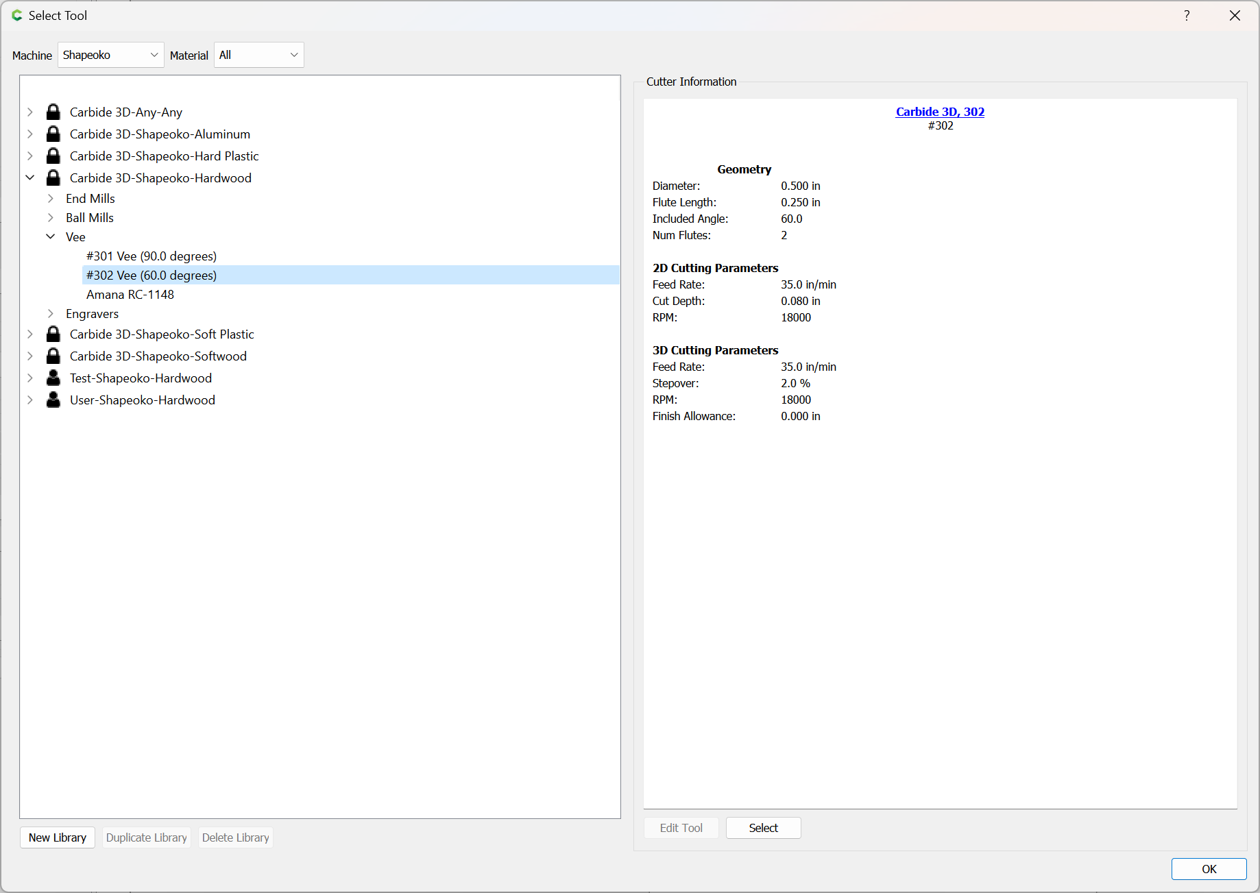
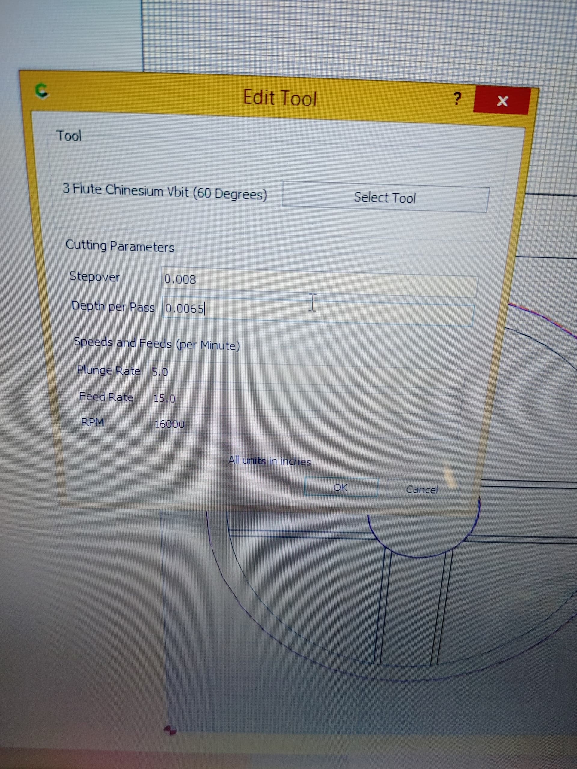
Would you mind sharing speeds and feeds for a 60 degree vbit? I’d need to add it to my tool library for both wood and aluminum. It’s this these ones here: Amazon.ca
Machine a mirror imaged negative of this as a fixture, insert the part into it, then cut the first toolpath registered w/ the fixture to complete things.
What do you mean by first toolpath registered with the fixture?
I can predict I’m going to have issues zeroing the part once it’s in the fixture. Any ideas on the best way to proceed?
Thanks again Will for coming through with some amazing instructions. I’m going to have a few questions once I get going on that (tomorrow).
Today I just had a bit of time to play with the vbits. It’s important that I can get them to work with aluminum because pretty much everything I’ll be making and selling requires it.
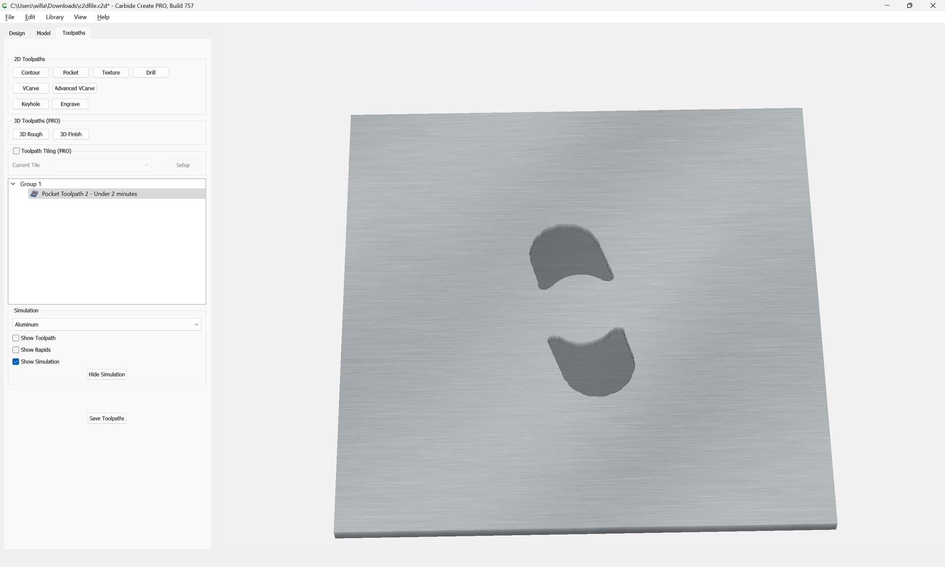
I did some quick tests and have some promising things to share (attached).
The more conservative depth per pass seems a bit nicer on the machine (less noise). It’s not really making chips very well at that DOC but it seems to work anyway lol.
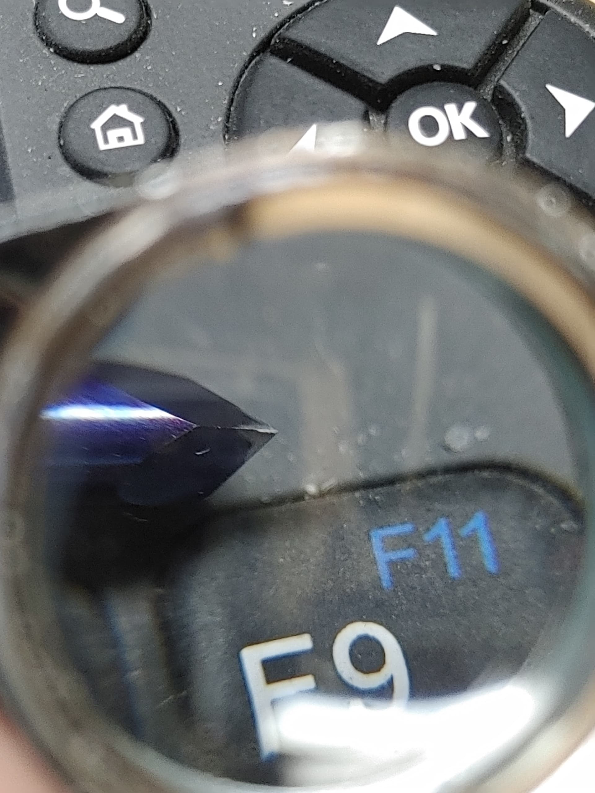
The bit seemed to hold up well after the small test. Whats seen in the image that looks like a rounded over edge is actually just aluminum that I was able to pick off. No heat on the bit at all.
I did an initial pass then a clean up pass to remove all the build up.
I’ve run into a problem and it’s a bit confusing. Been playing with it for a few hours and I’m not sure if there’s anything I can do to fix it.
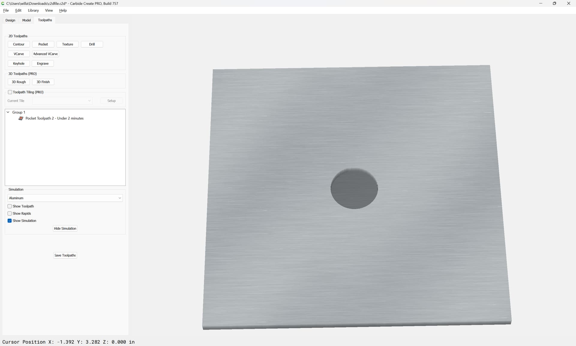
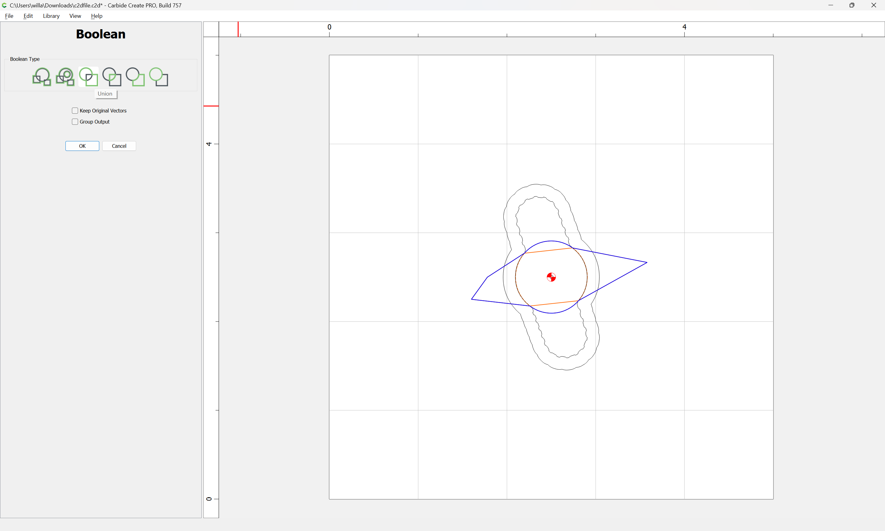
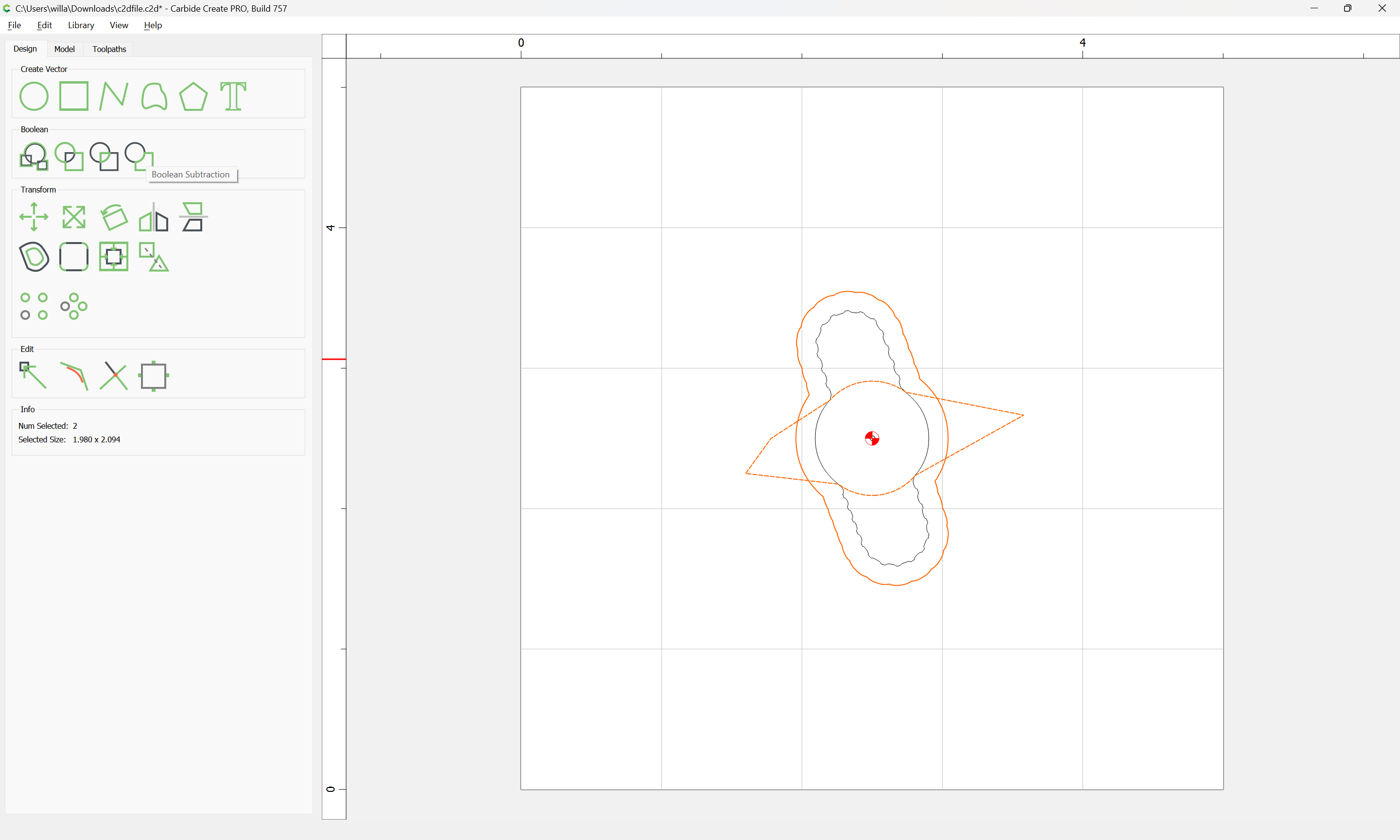
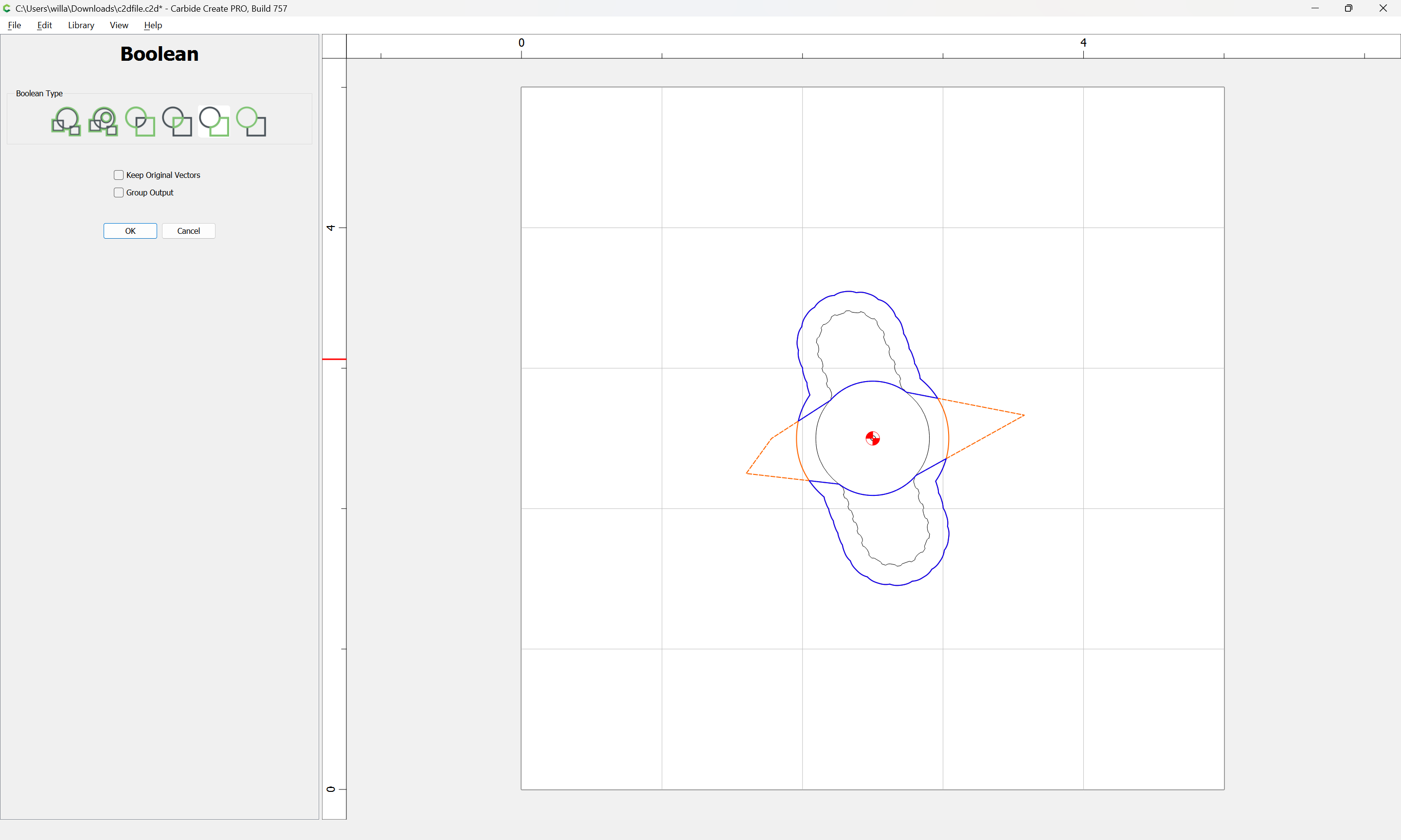
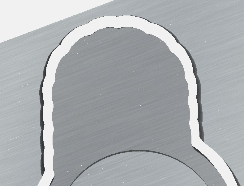
When I create the offset at 0.125" (exact measurement of endmill) the edges of my design stay nice and sharp and crisp. When I add the 10% it starts to round over. That 10% is directly impacting the material being cut away from my edges leading to rounded grips (see attached image).
It seems there must be a solution to this but I’m unable to find it.
I assume the 10% is added to prevent slotting around the entire workpiece causing premature wear to the endmill. I could reduce it to 2-5% and the rounding would be less, but it’s still negatively impacting the design. Any solution to this?
Lets say I was trying to machine a clamp which is as precise as possible to the design, would it still be possible to use that technique?
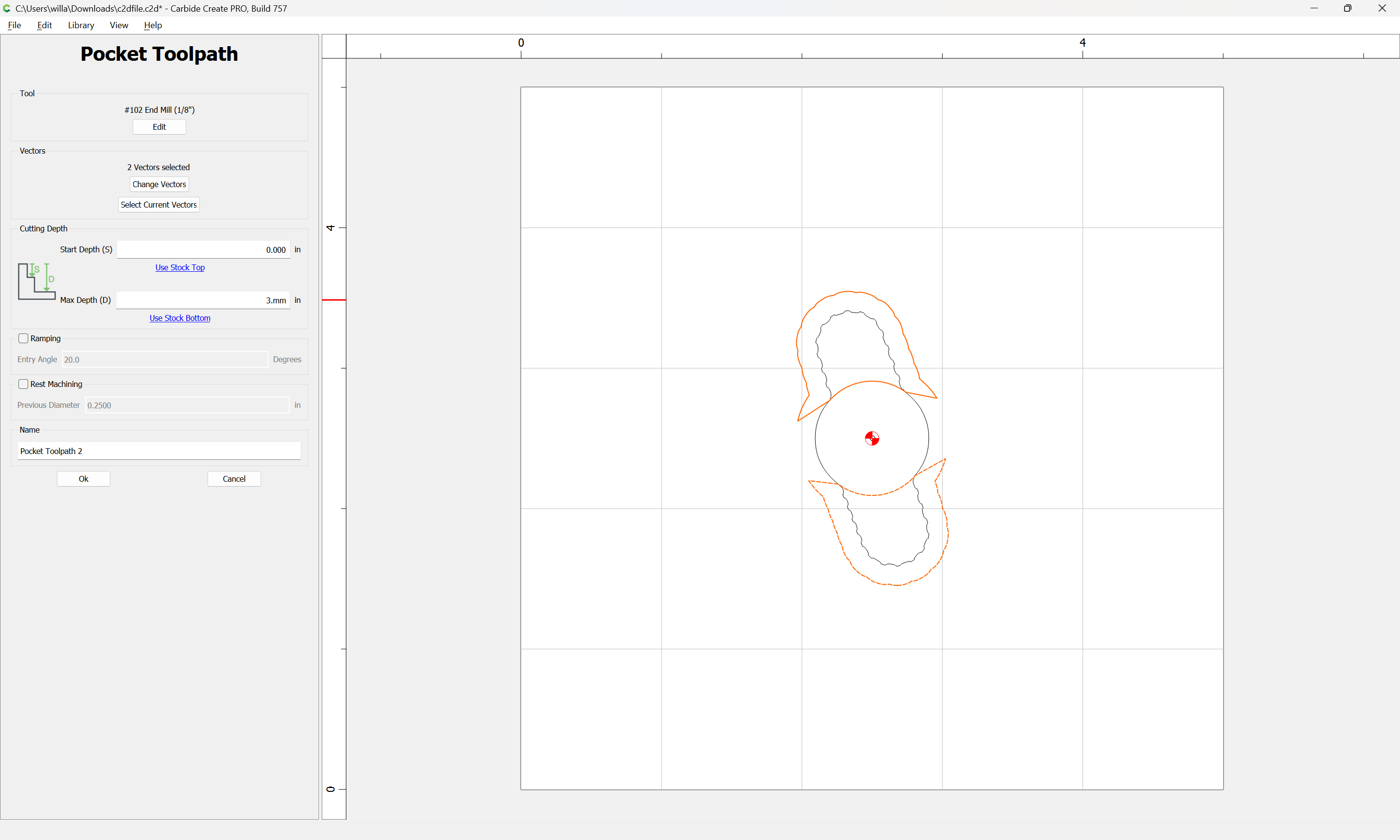
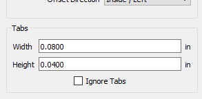
Does this seem like an ok clamping / tab setup or am I being too stingy trying to save material and causing risk? My first time using tabs, just want to be sure.
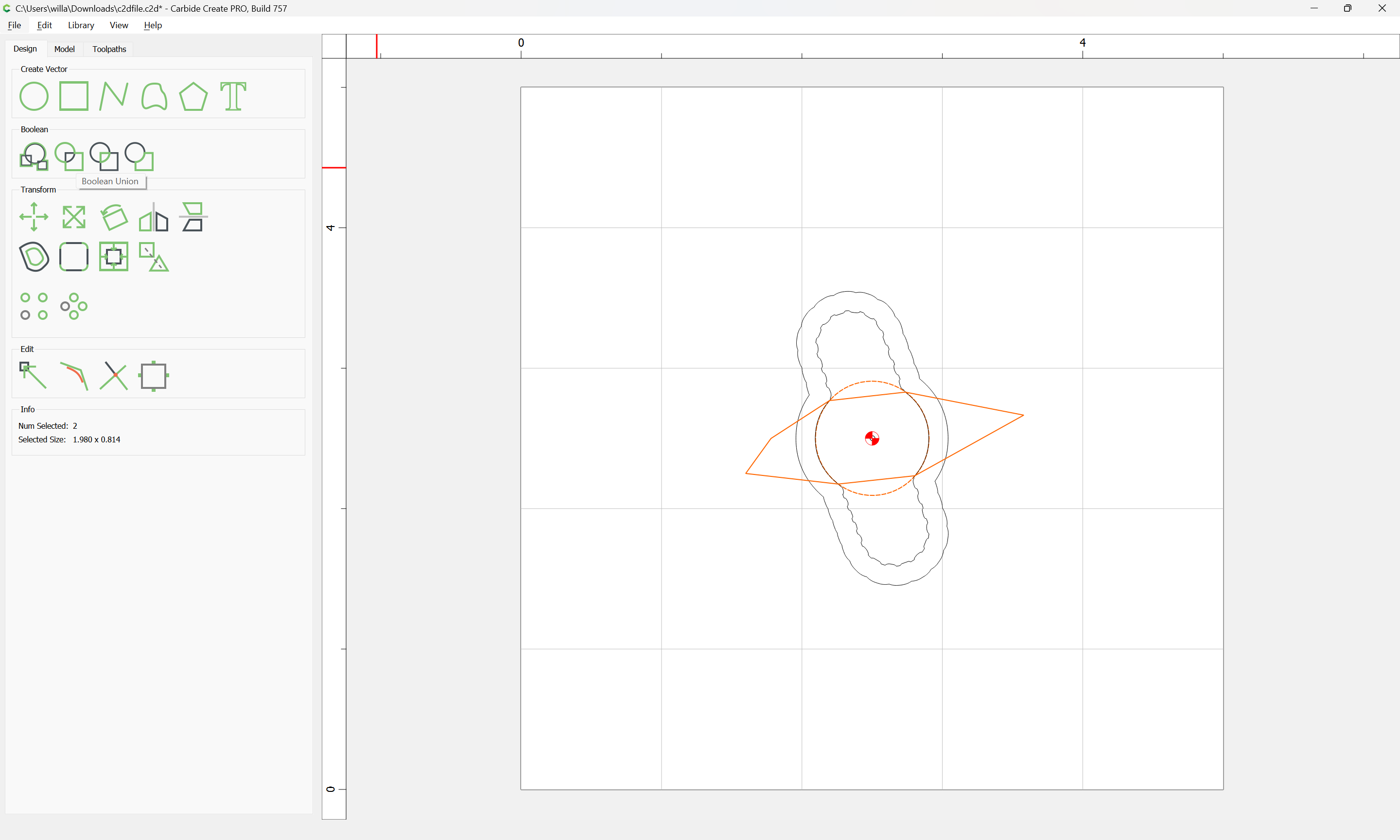
Yes, sorry vertex points are your nodes. In illustrator, if your shape doesn’t make a solid, then those little nodes or points are not connected. They are overlapping, so you have to weld those points together.
Points in illustrator, nodes in Carbide, vertex points in 3-D max, all the same thing just called different names.
Ty for explaining. I think everything is all connected as far as I could tell. Kind of expecting something to go wrong but nothing to do but push forward at this point. Gonna try to make these now, I’m feeling brave enough to give it a shot wish me luck
All good man appreciate your help / advice. Got any photos of some of the knobs you’ve made? Which machine are you running?
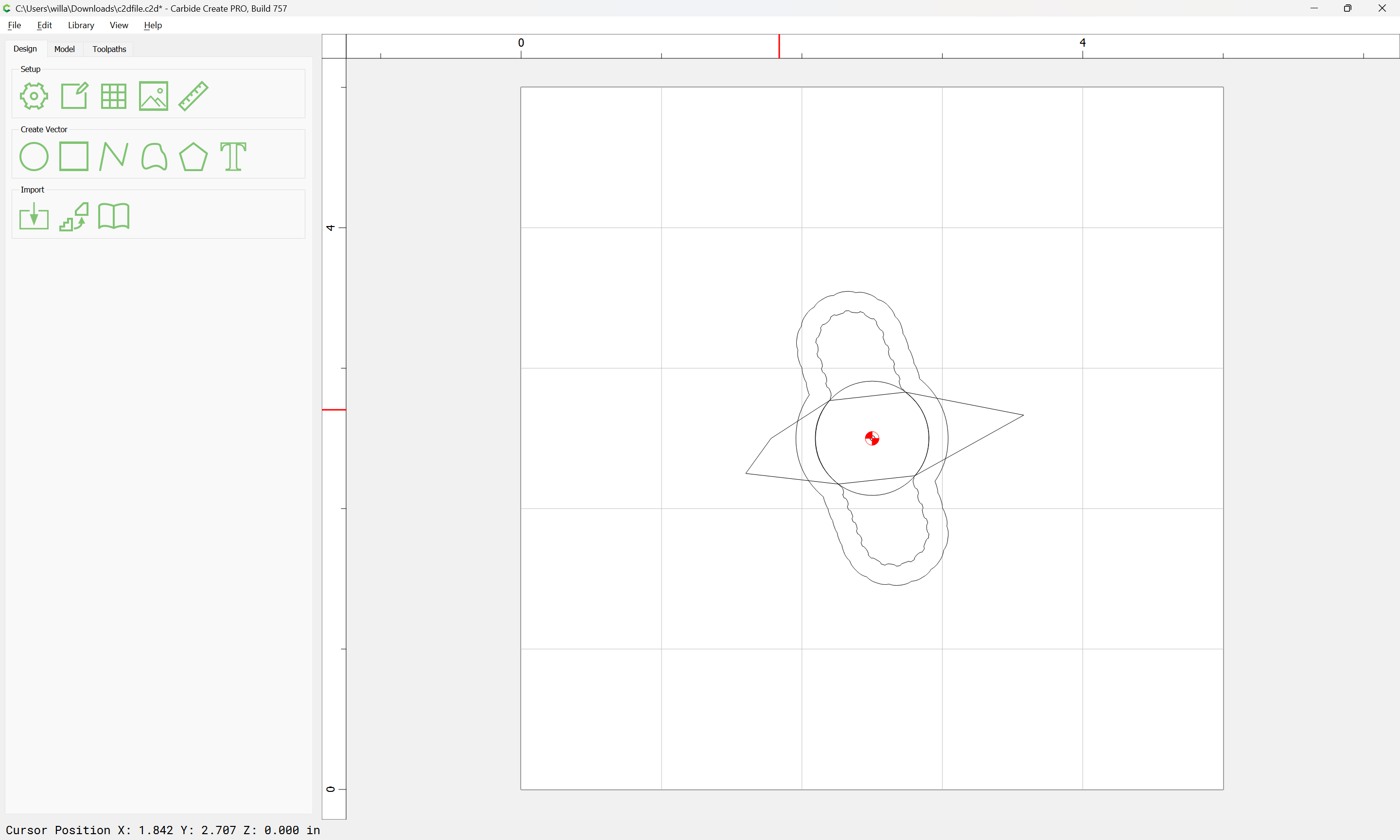
If you were to make the knob posted here from scratch in illustrator what’s a better way to go about it?
Scuffed up my first one with improper feeds and speeds. I’ll try to salvage it tomorrow, but might be best just to start fresh lol.
I did feeds and speeds testing in aluminum about 3 weeks ago… for whatever reason I didn’t record the results, and today I loaded in a bad stock profile that was running way too aggressively.
Project failed and cancelled Was making good chips and using air blast but eventually end mills were gumming up every 10 minutes. Not sure what kind of aluminum this is, so that might be part of the issue. I believe the machine was skipping a bit and having some accuracy issues which I’ll have to address in the near future.
Doing the large offset would have helped with chip clearance instead of slotting but if it affects the accuracy of the design it’s a no-go.
The good news is I learned a lot and these were just parts to make my setup better, non-essential.