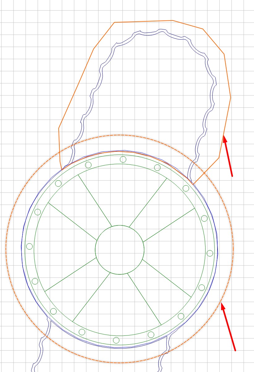
I’d be willing to try to make it in carbide create, but I don’t think it’s possible to create the pattern around the lines and bends etc.
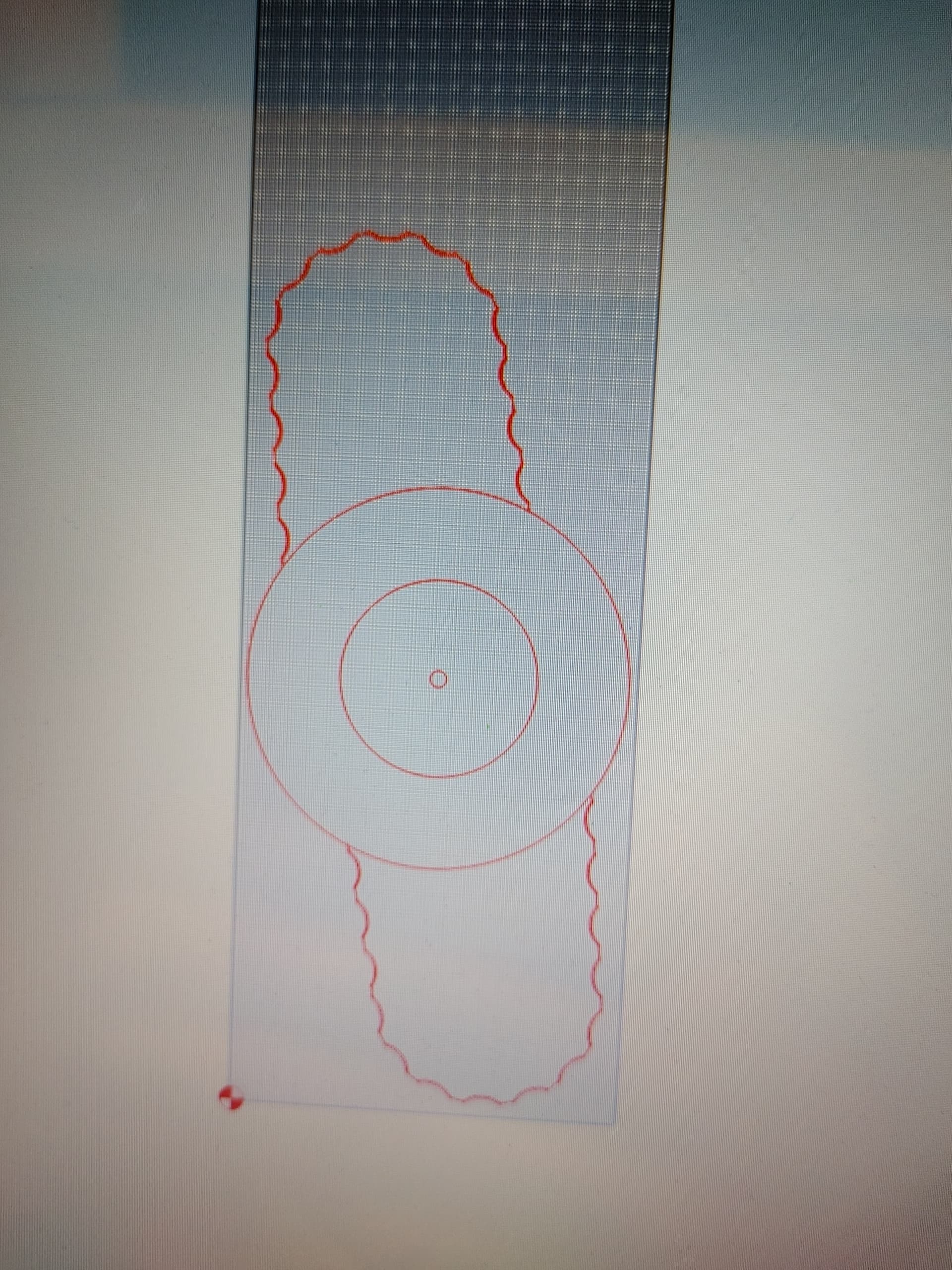
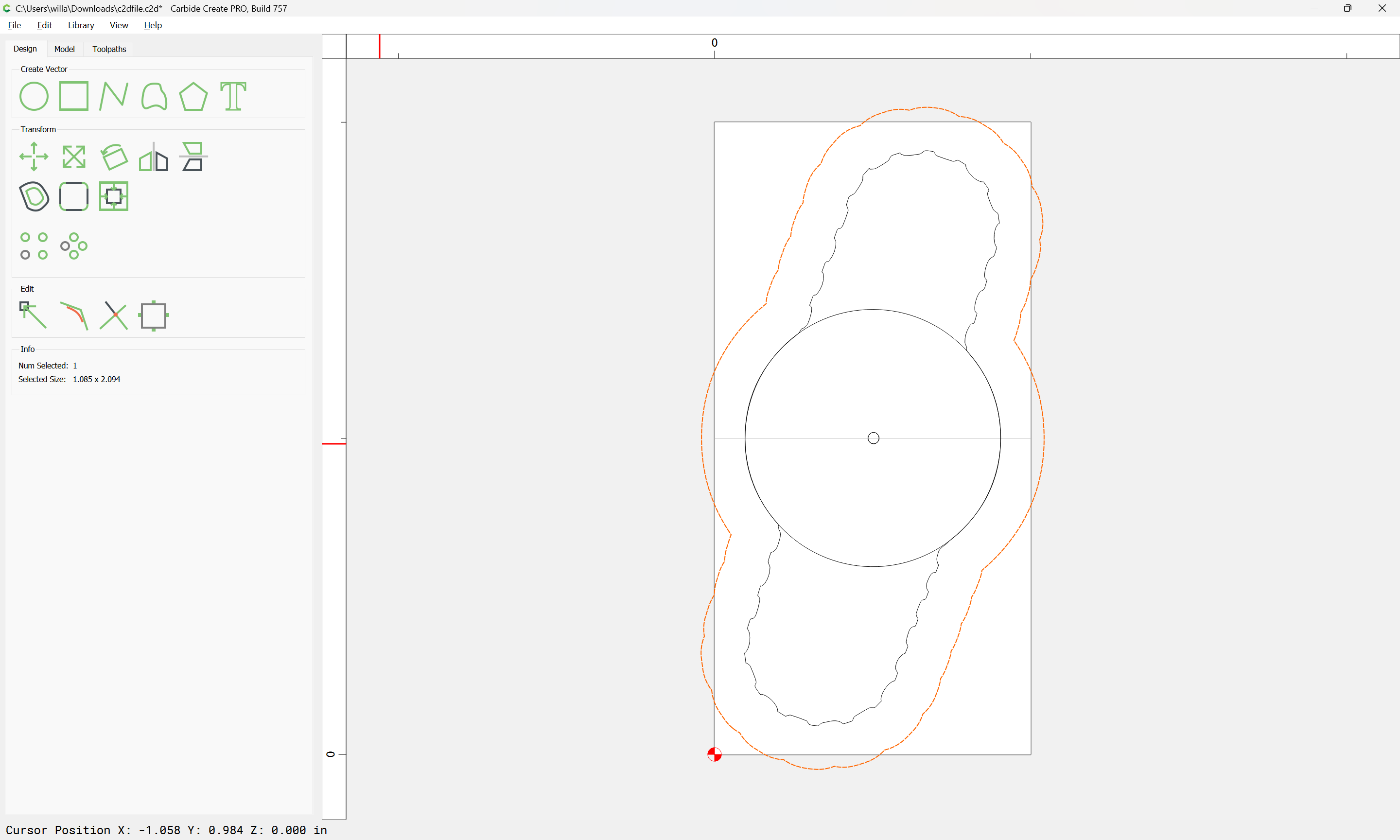
When I load the SVG into Carbide Create it looks ok until I zoom in. It’s doing weird things that don’t show up in illustrator. I’m thinking part of the issue is I didn’t merge the individual pieces? I created a custom brush and applied it to the lines and semi-circle. Everything is still separate, and all my different elements are all just stoke, no fill, no for whatever reason it wont let me merge them
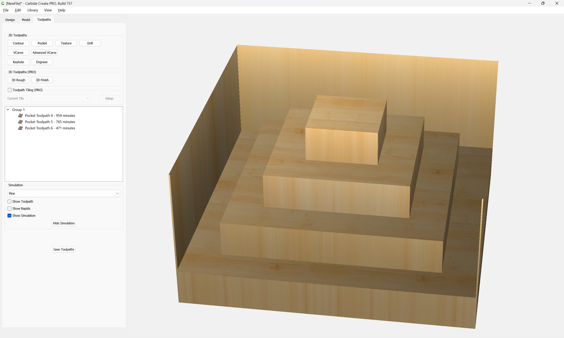
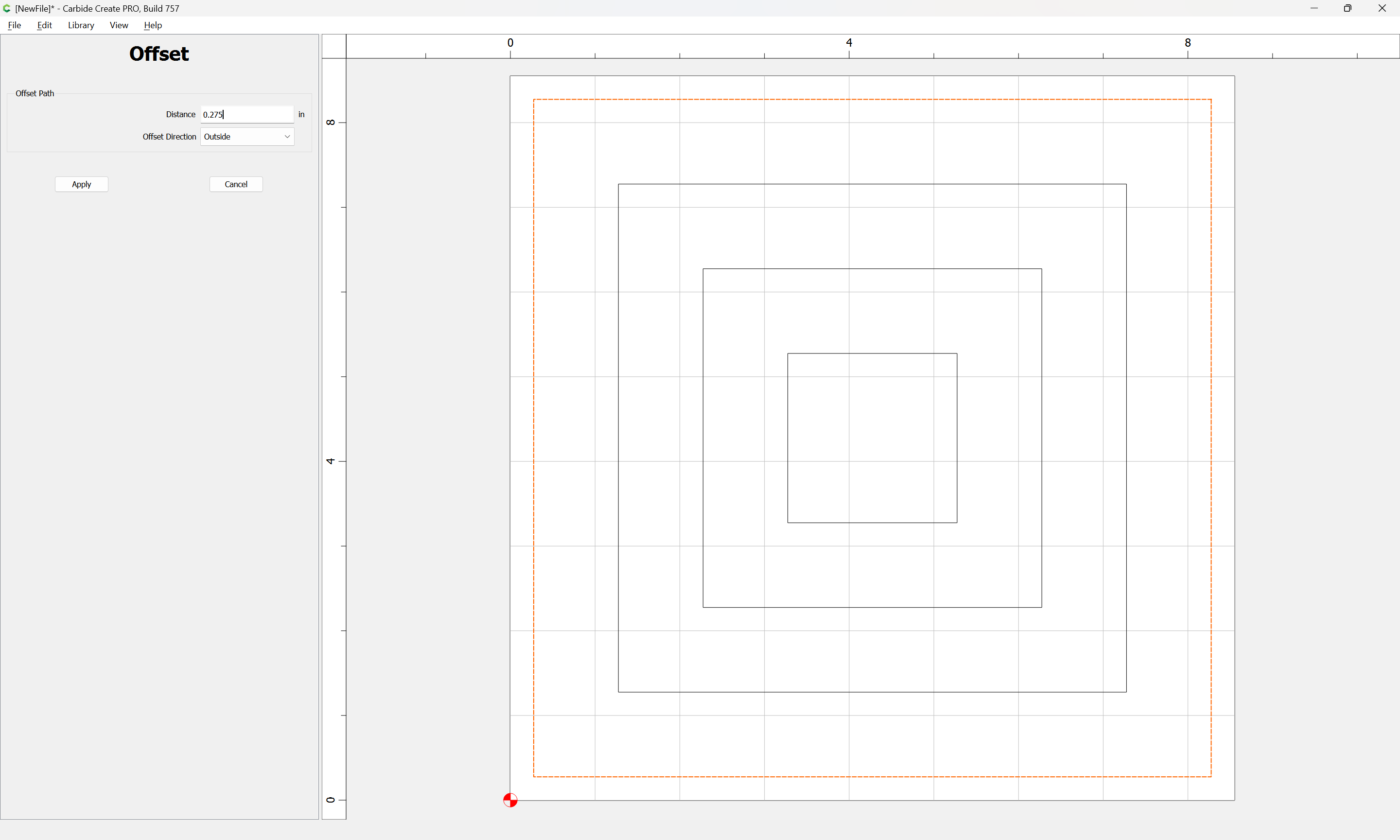
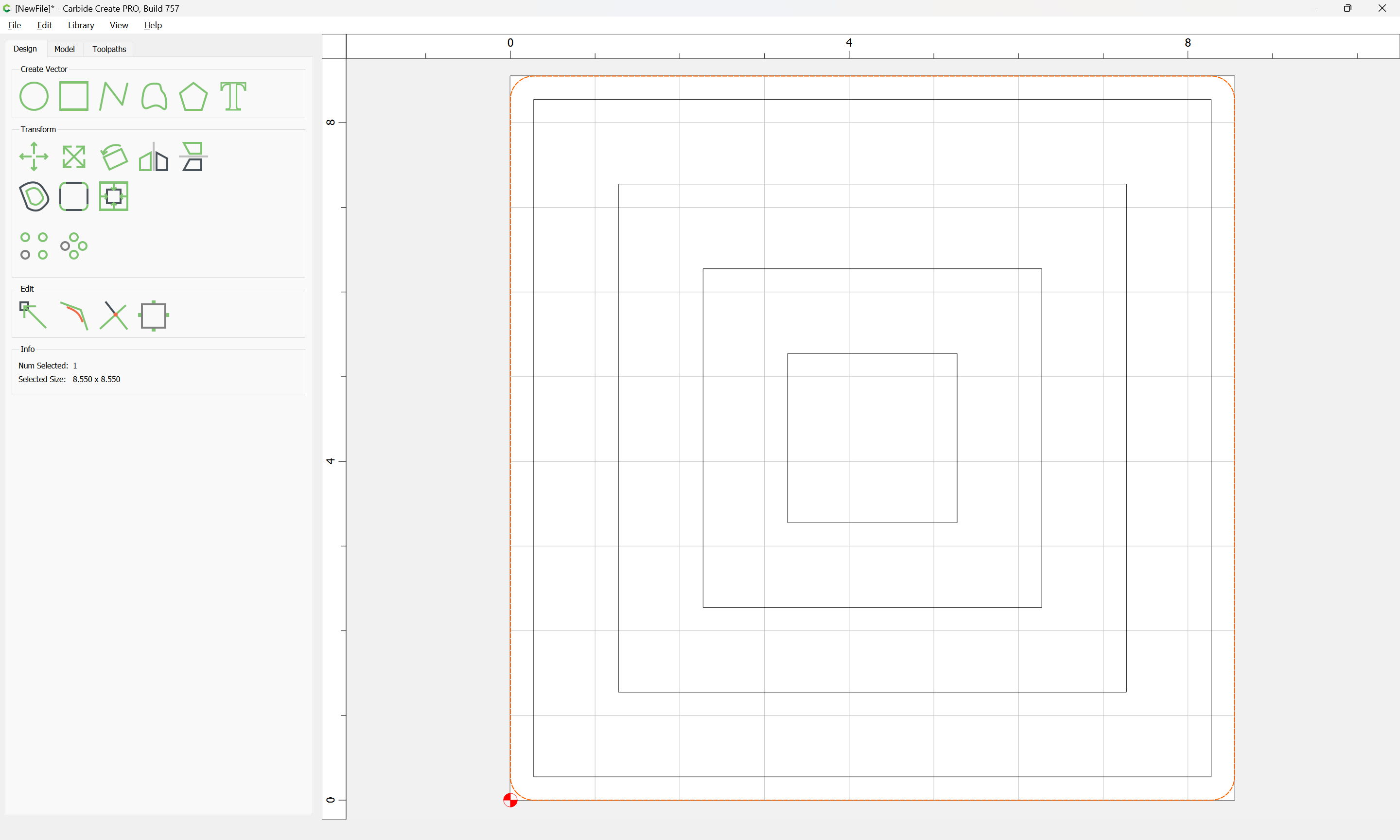
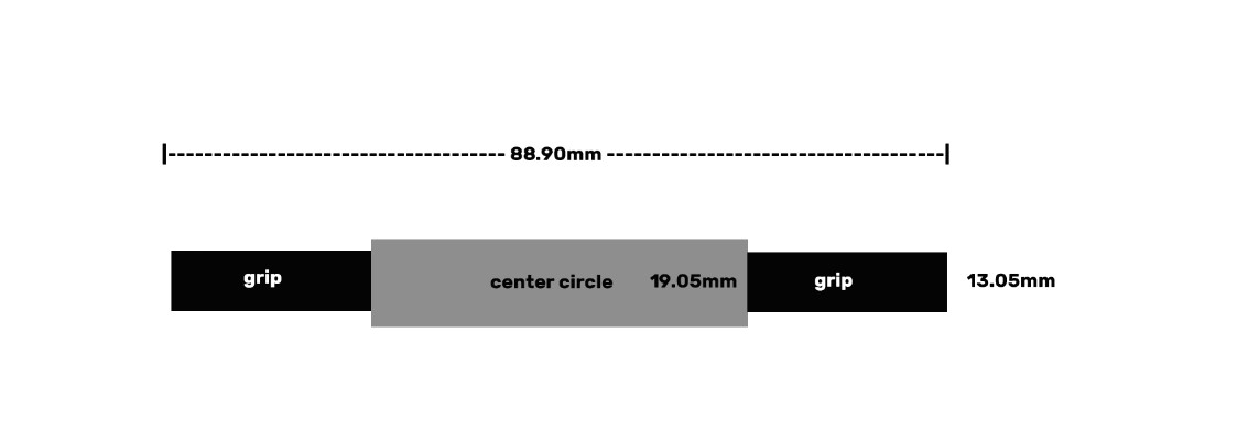
When I load the SVG into Carbide Create it adds some weird lines for some reason, also its not respecting the design when I simulate toolpaths. It takes off way too much material. I think I need to create an offset from the initial design menu. Going to play with that tomorrow.
Post a PDF exported from AI and the SVG? Note that the SVG should be made by exporting and clearing the “Responsive” checkbox.
Note that dimensions in Carbide Create will match the object geometry, not including stroke thickness, so if (for example) you are creating a 1.5" circle, w/ an 0.5" stroke, you will not get the 2" object, but rather the 1.5" of the raw geometry w/o the added thickness of the stroke weight.
I have made a lot of svgs out of PDFs. Sometimes the svg comes in multiple pieces and I try to join vectors or blow the image up and edit the nodes to connect them. I was making a cam and when the svg was formed and I did a contour on the outside some of the pieces would cut on the inside of the vectors. I had selected outside contour but since the pieces were really not connected CC thought it was going to cut on the wrong side which I guess it thought was the outside.
When importing the svg I usually make sure the whole svg is selected and use the join vectors to make one vector instead of 2 or 3 that the svg is made up of. If that does not work then edit the nodes to join them. You really have to zoom in to see that the parts of the svg do not join together.
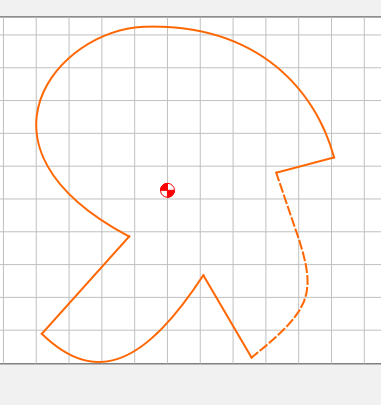
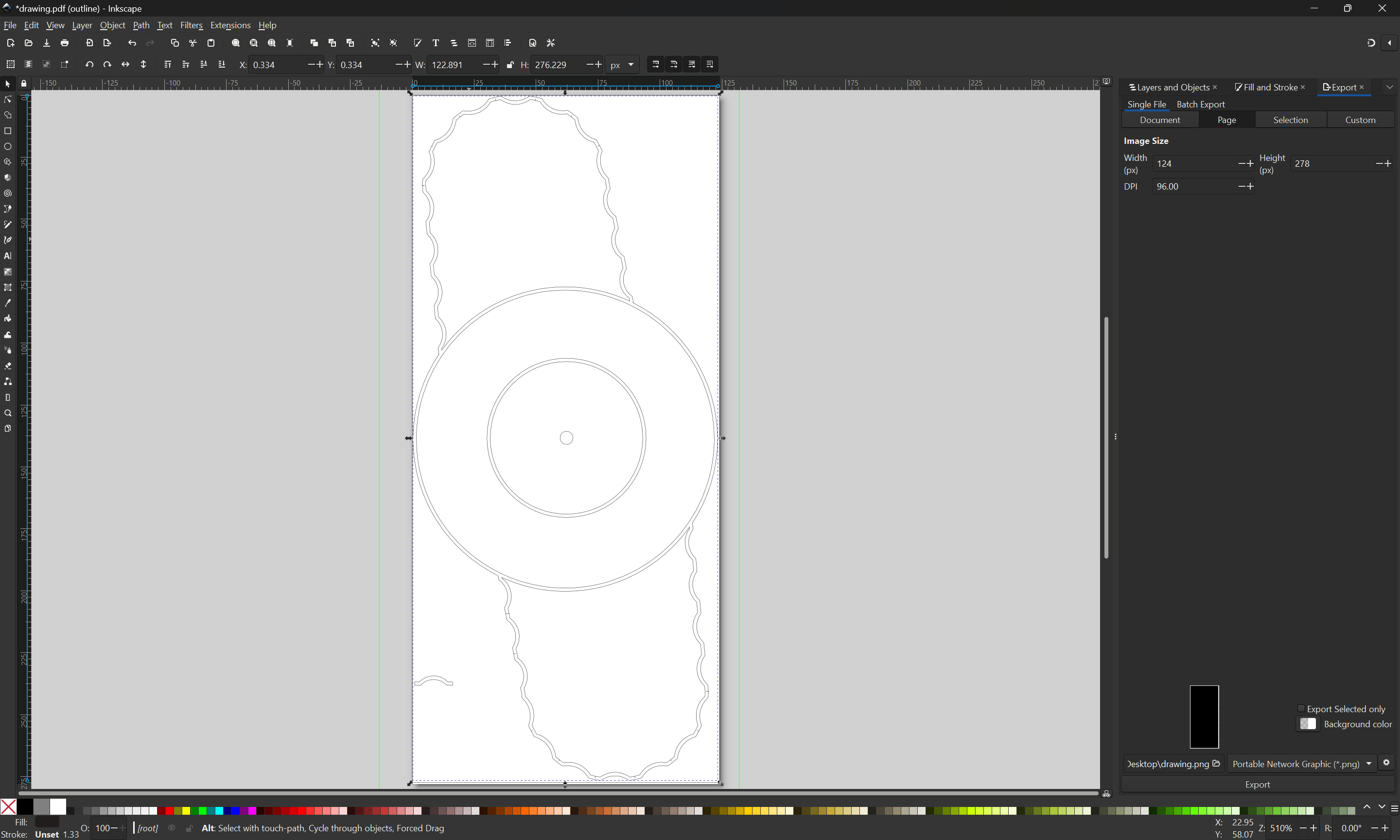
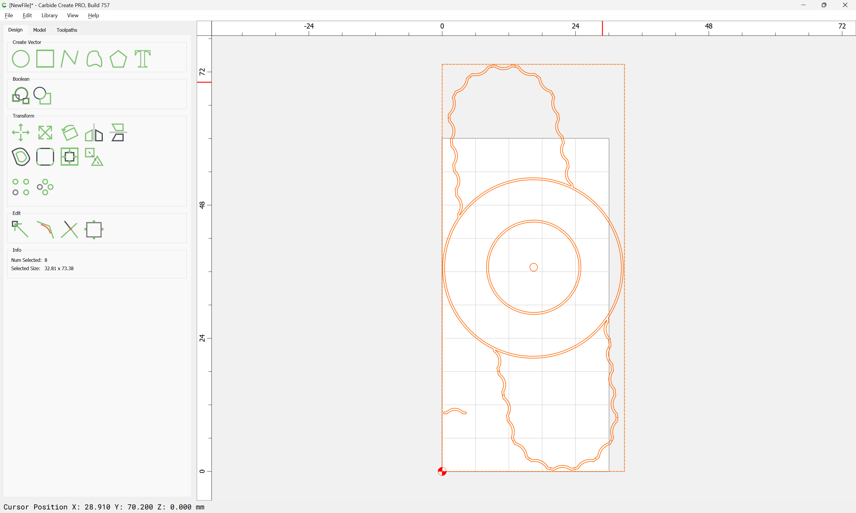
Here is an example of a pdf that I made into an svg in Inkscape.
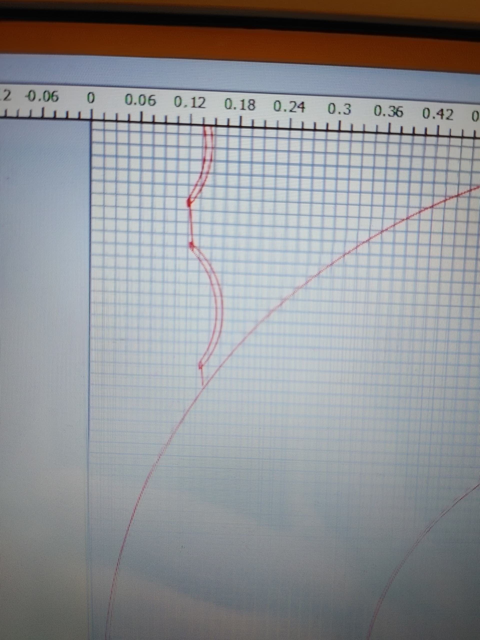
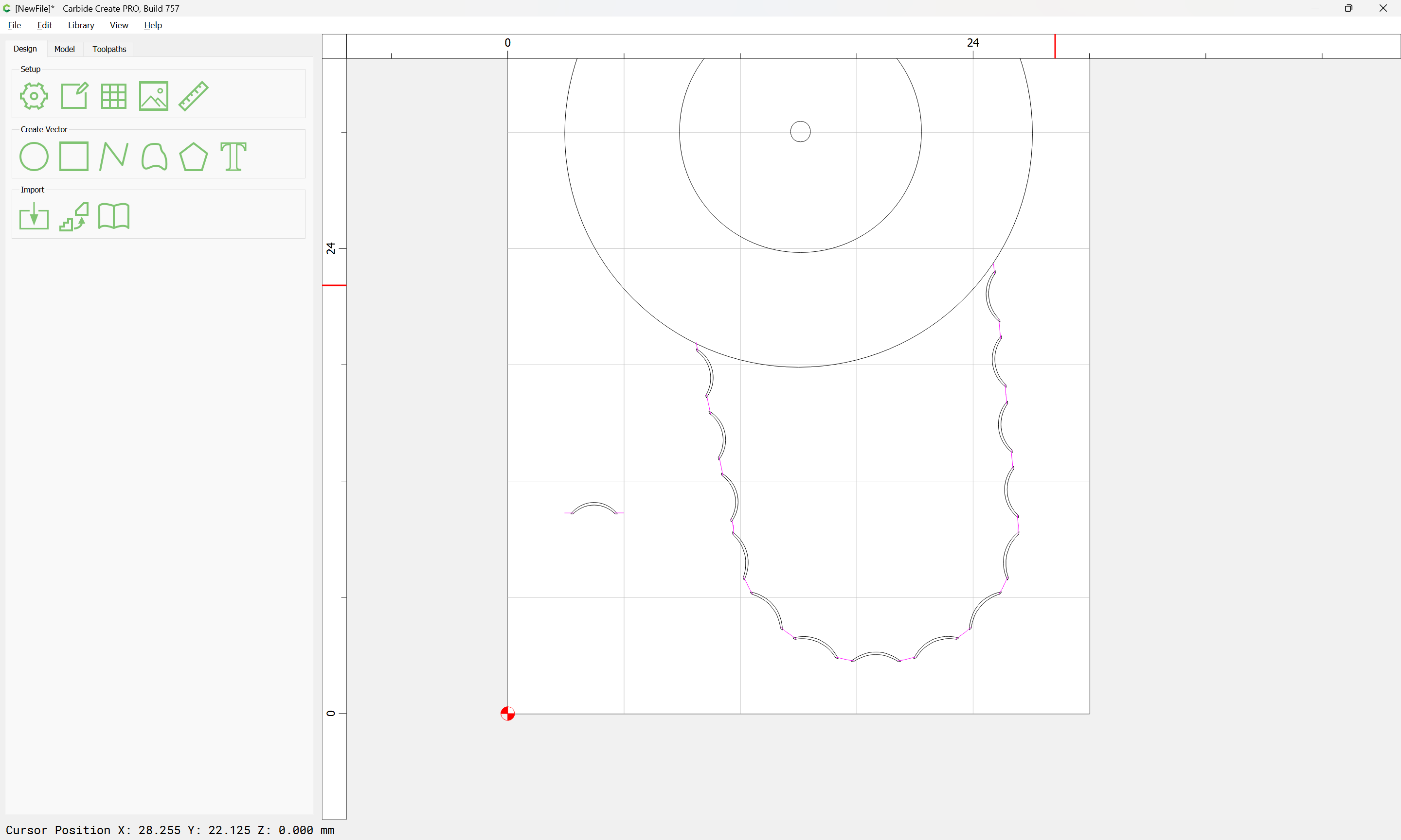
The first image is the cam converted and imported into CC
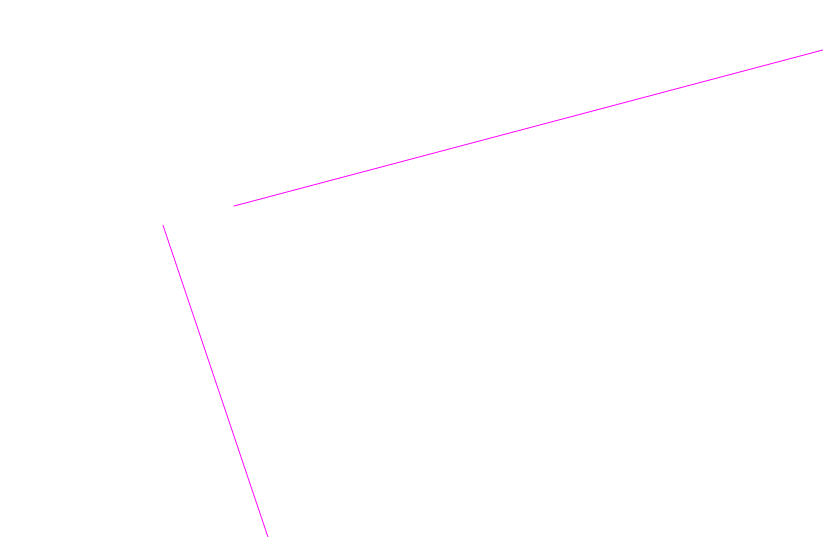
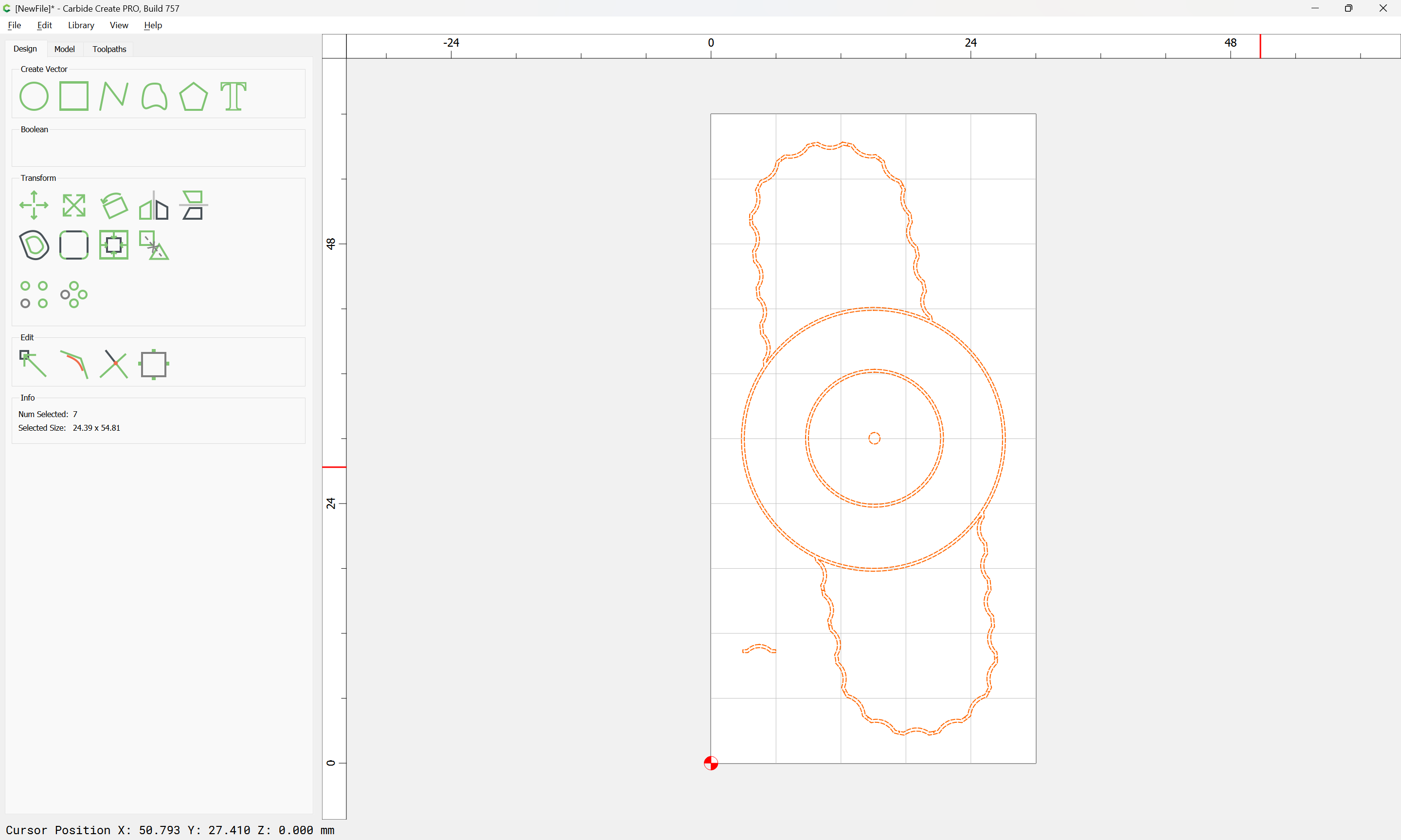
I made a contour tool path for outside and you can see some of the parts are cut on the inside and overlap.
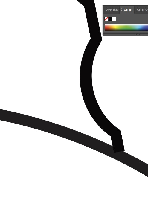
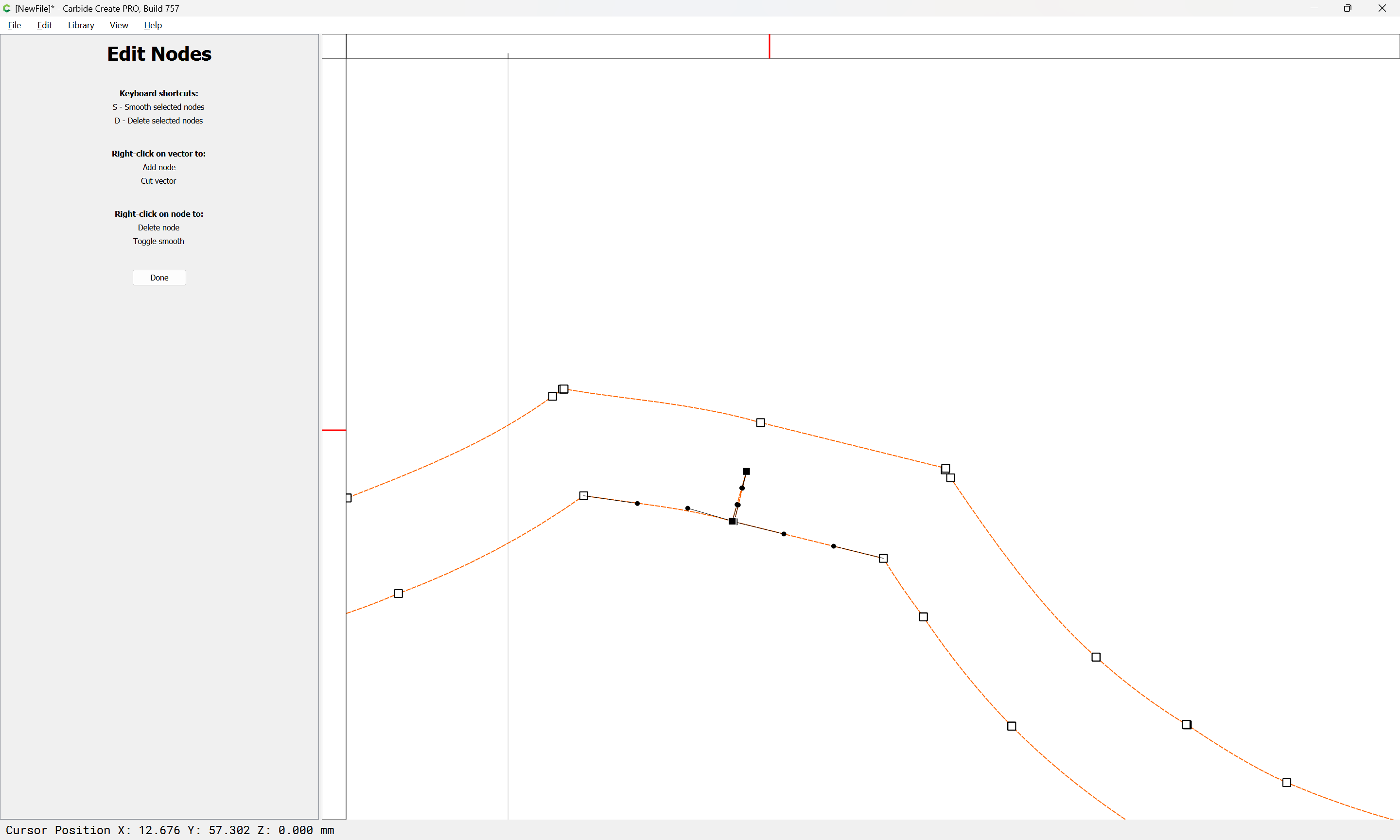
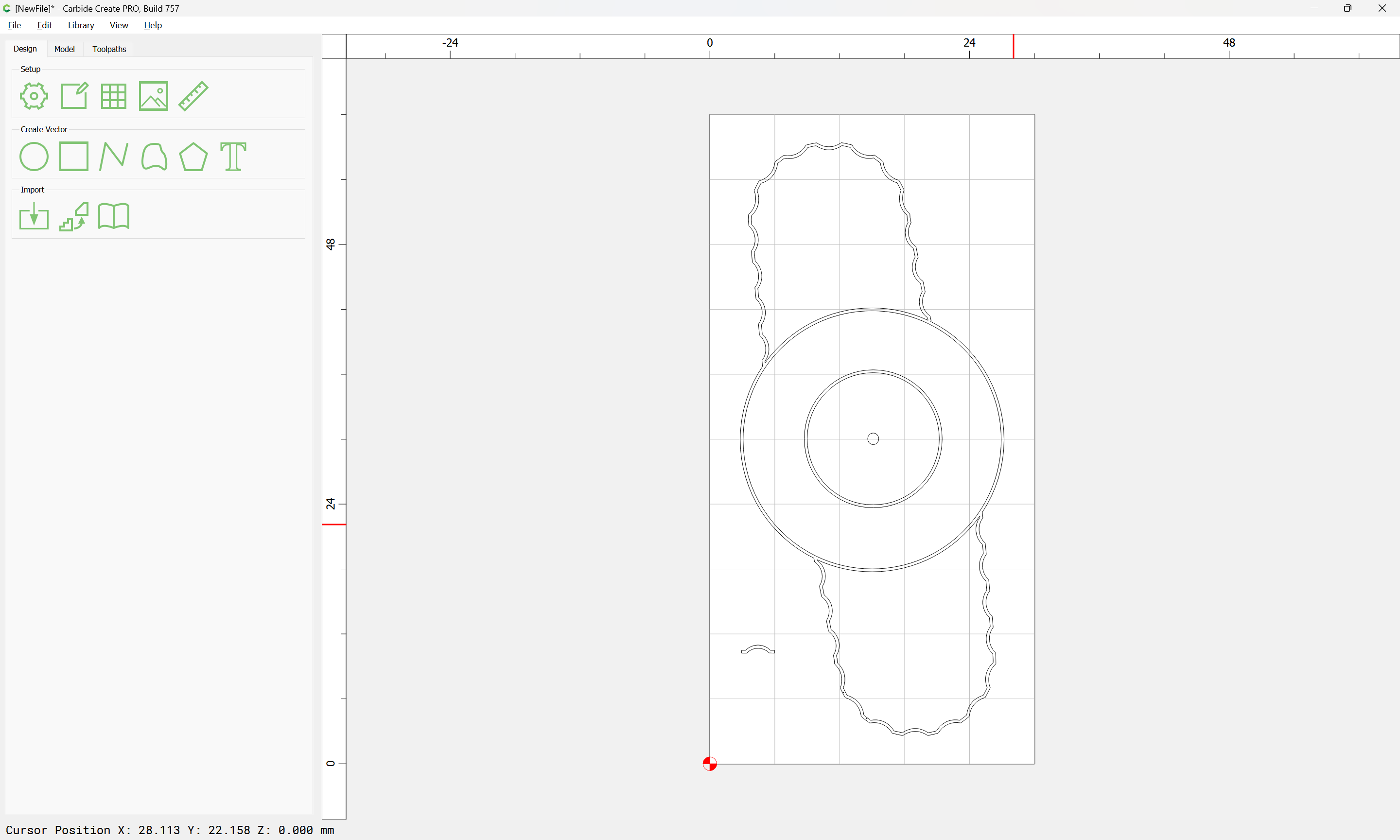
So I edited the nodes by selecting all the parts of the cam and was able to join it all together to make a single vector. I suppose who ever drew this was sloppy or the conversion did a sloppy job.
I’m still new to illustrator. I’ve worked with it in the past but just making some images for web design. I think what you mentioned about connecting the nodes might be spot on. I didn’t connect them. When I make a circle there are 5 nodes: left right up down and center. I wanted to connect my lines to areas of the circle that didn’t have nodes there so I just visually lined it up without linking it. I’m not sure how to make a new node, delete nodes or anything like that.
I’m going to have to spend 4-5 hours today watching tutorials on illustrator, I’ve gotten pretty far on brute forcing the design but I think I need to step back and at least learn the basics of the program.
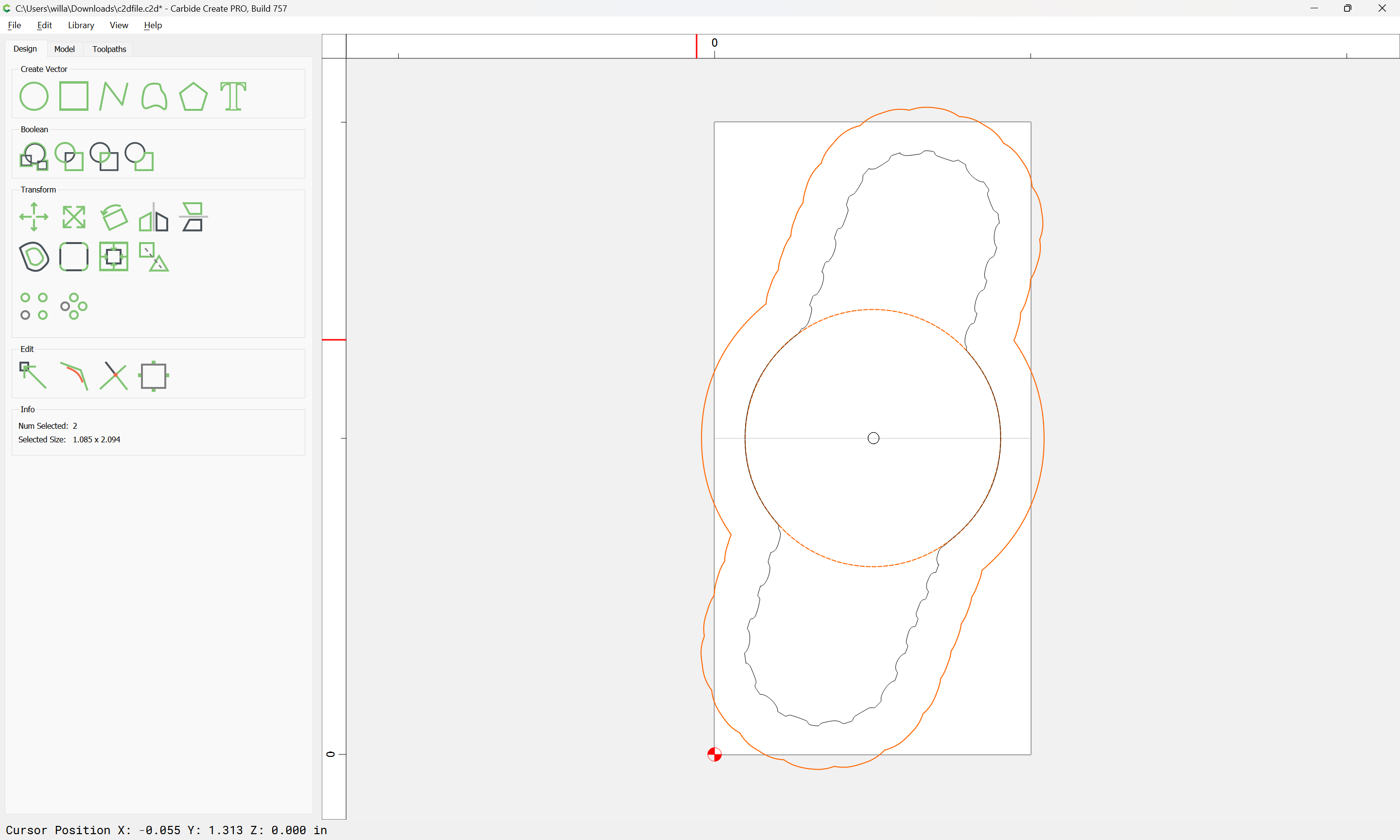
The way to make this into a closed design would probably be to convert strokes to paths in Adobe Illustrator and then use Boolean Union to combine things.
Wow! Really appreciate that information. You’ve done it! That’s a huge help for me, thanks so much. The solution makes sense. I researched what you suggested as far as converting the stroke and its pretty easy to do.
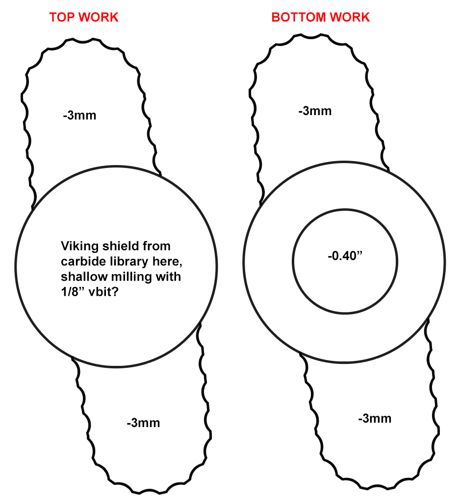
I’m trying to brainstorm the best order of operations to get 4 of these clamps made.
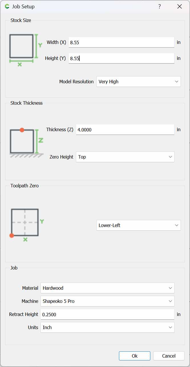
I’ll probably go with 3/4" thick x 3" wide bar. The clamps will be 3" in length.
Clamp down the bar stock in line with the rails to ensure it’s square
Contour around the exterior leaving 4 tabs
Mill 3mm off each of the grip handles
Shallow mill the design onto the central circle
Remove the workpiece and remove tabs
Mill a pocket in wood to fit the workpiece
Insert upside down and clamp on edges of central circle
I believe you will need to draw in the circles again, but otherwise it all sounds reasonable — I’d try a test cut in a piece of easily cut scrap before committing to alu.
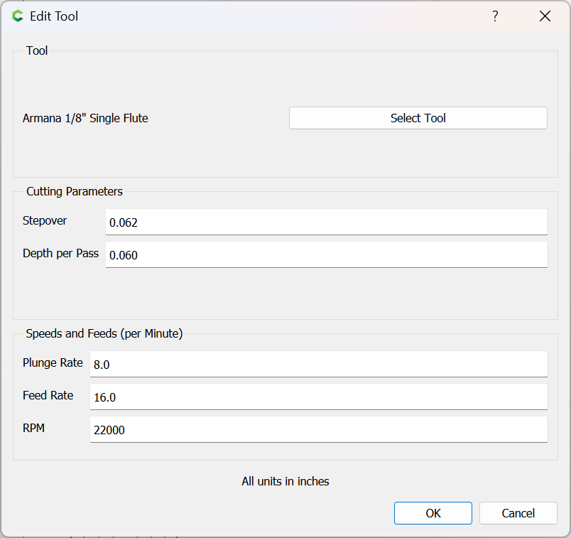
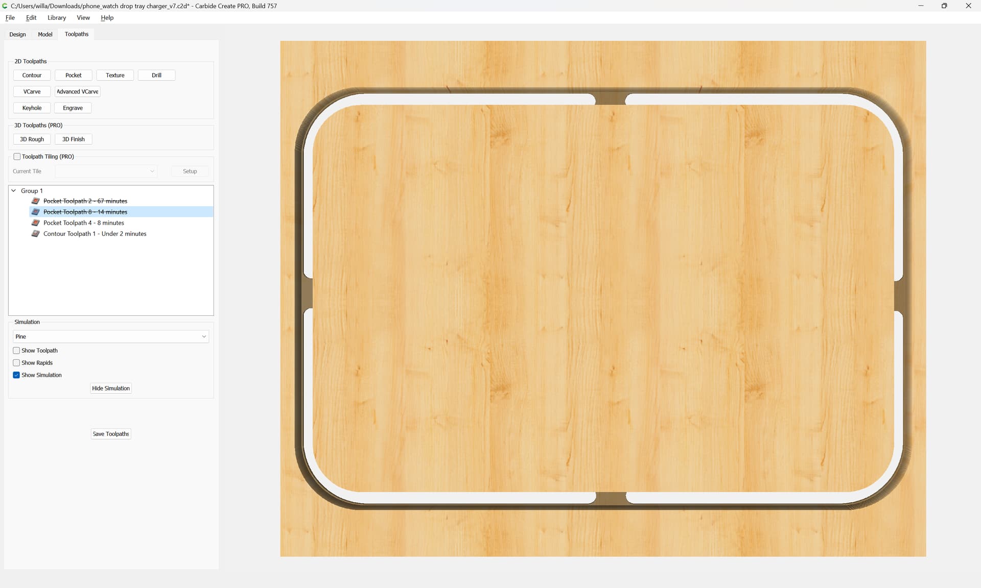
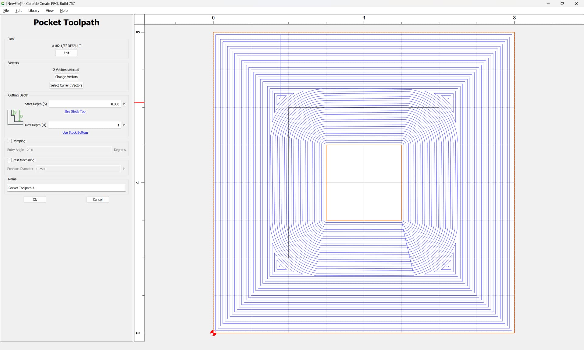
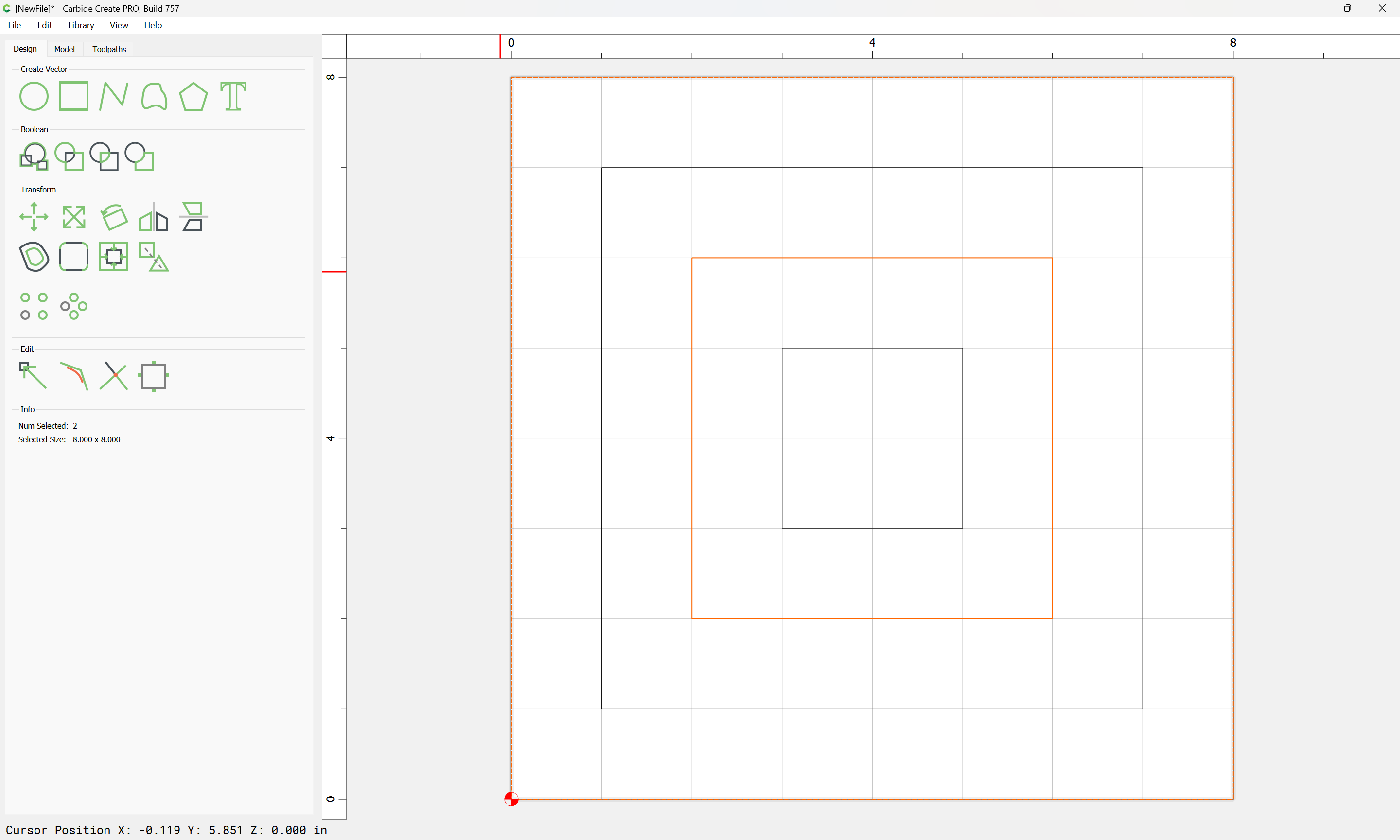
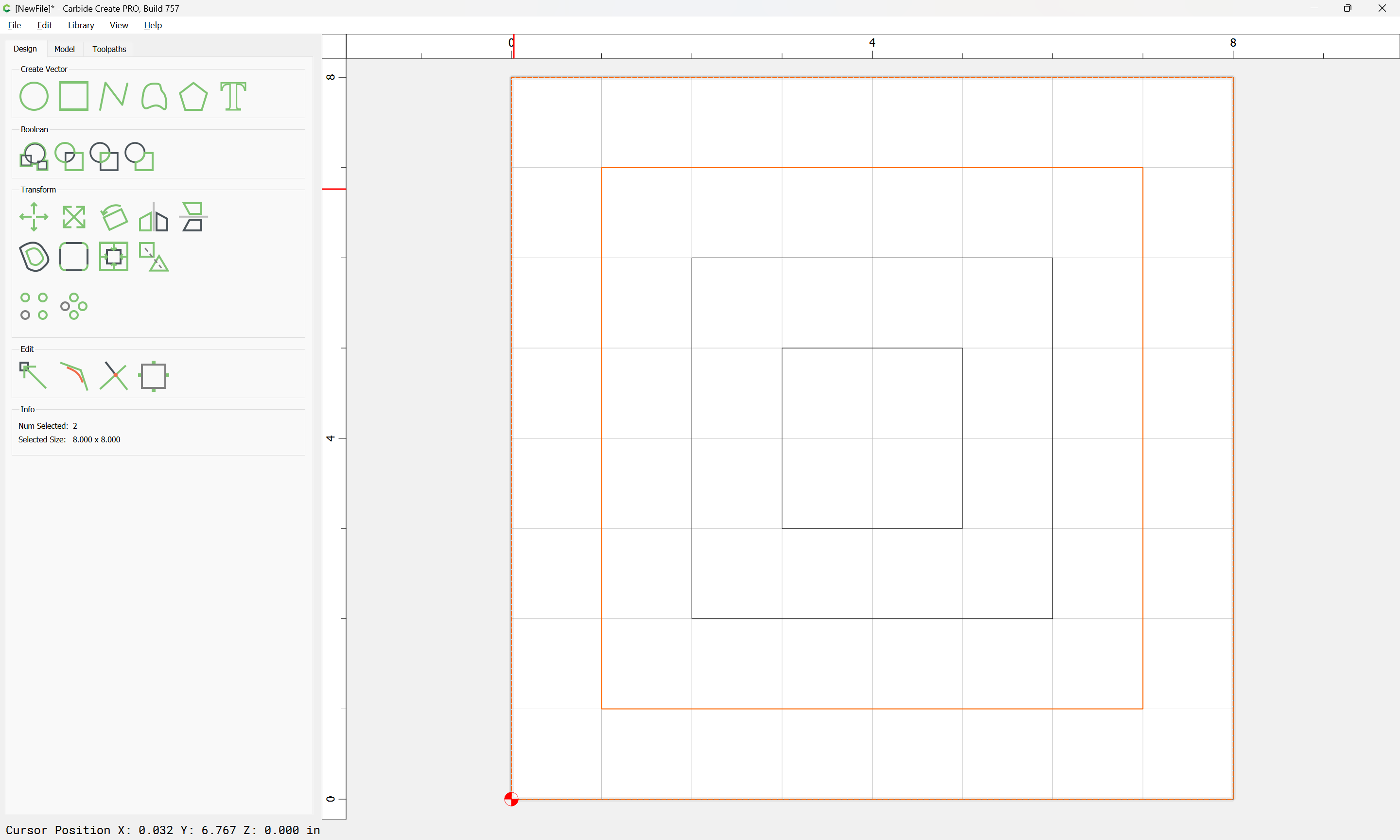
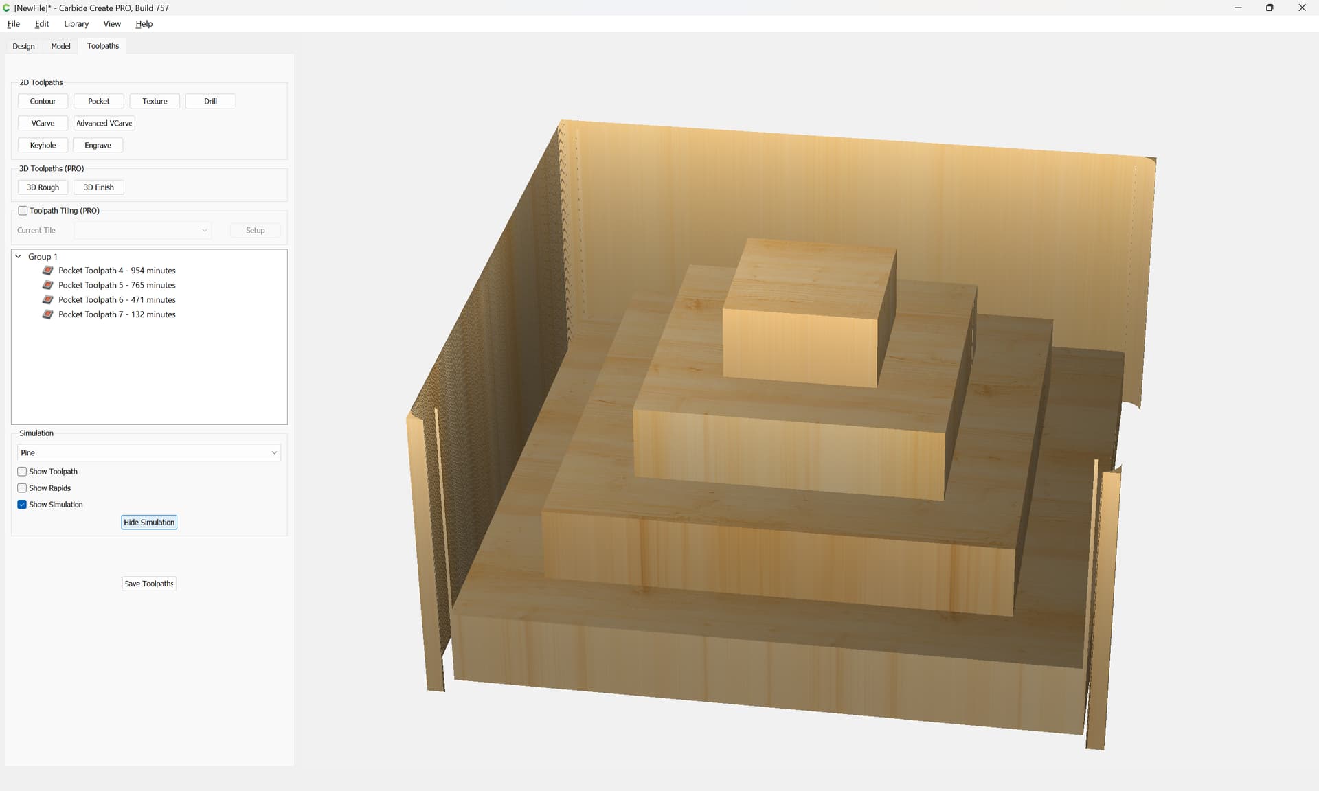
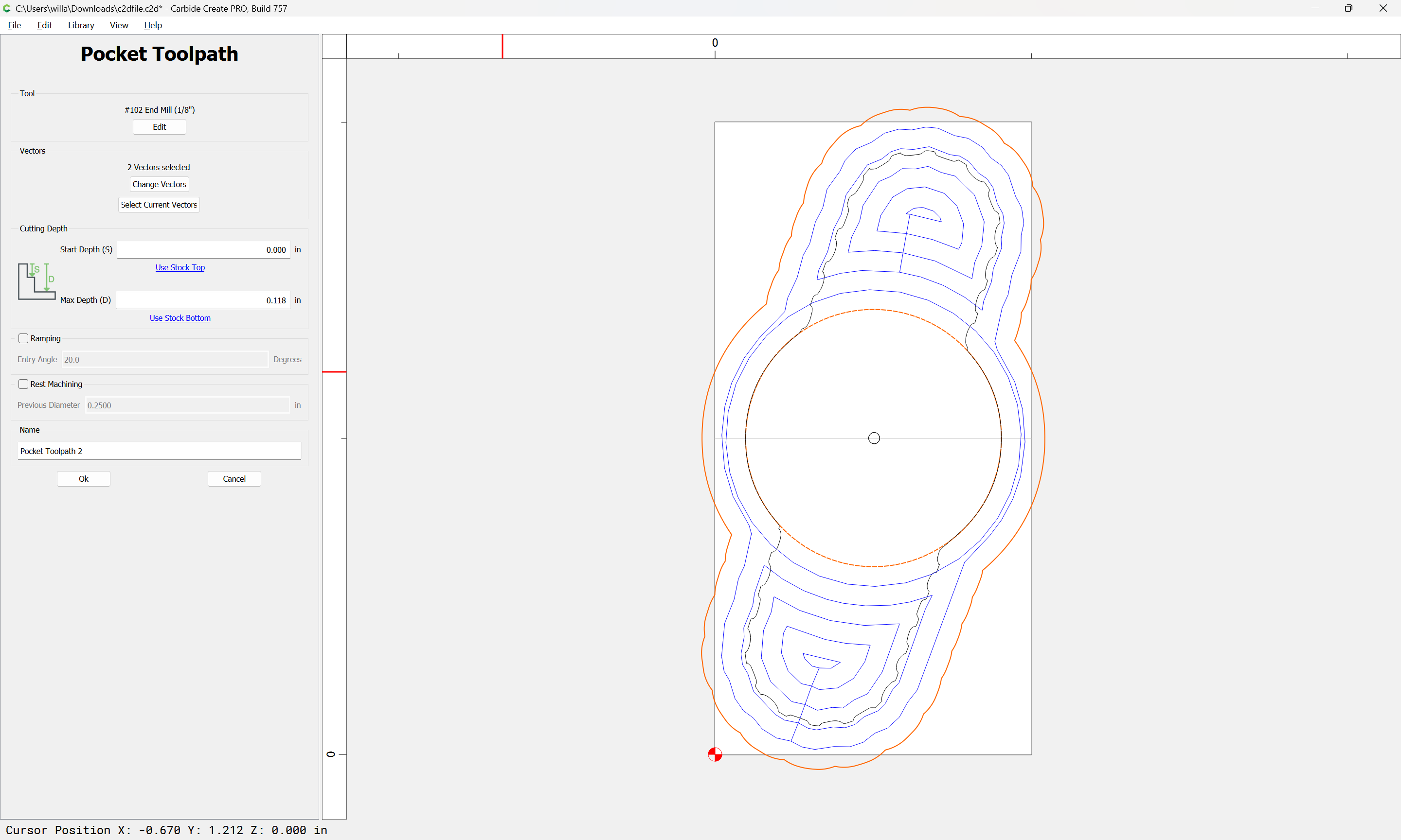
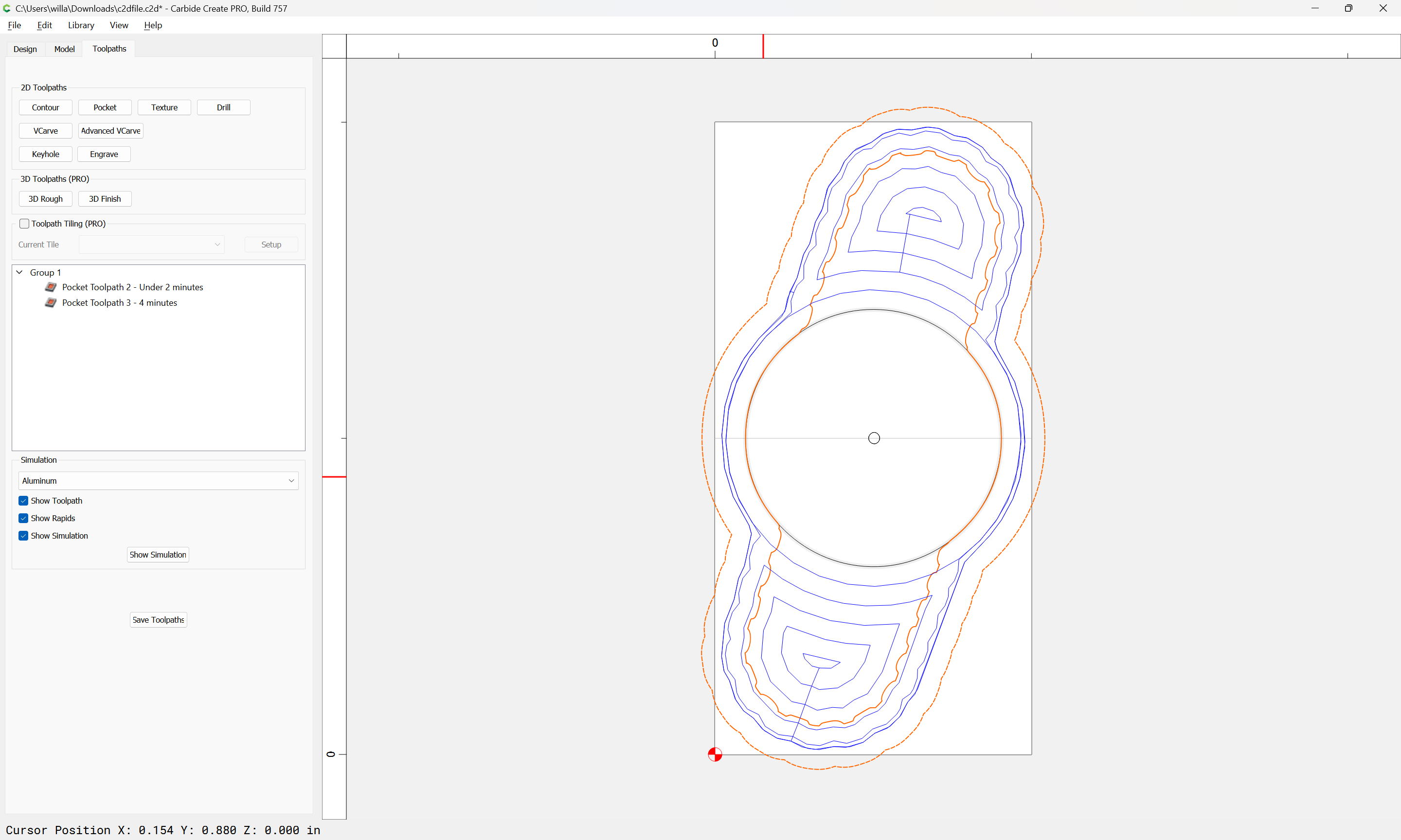
Finally got time to try cutting out a version in wood, and I’m running into a strange issue. Work file is attached, it always says 2 minutes estimated time to do a full contour or pocket into 1/2" thick wood. I triple checked all the settings and switched everything around in many ways. Any advice on what went wrong? problem.c2d (80 KB)
Hmm I’ve been playing around with things but I’m getting confused. I think my design is a bit unintentionally overly-complex… but it’s forcing me to learn.
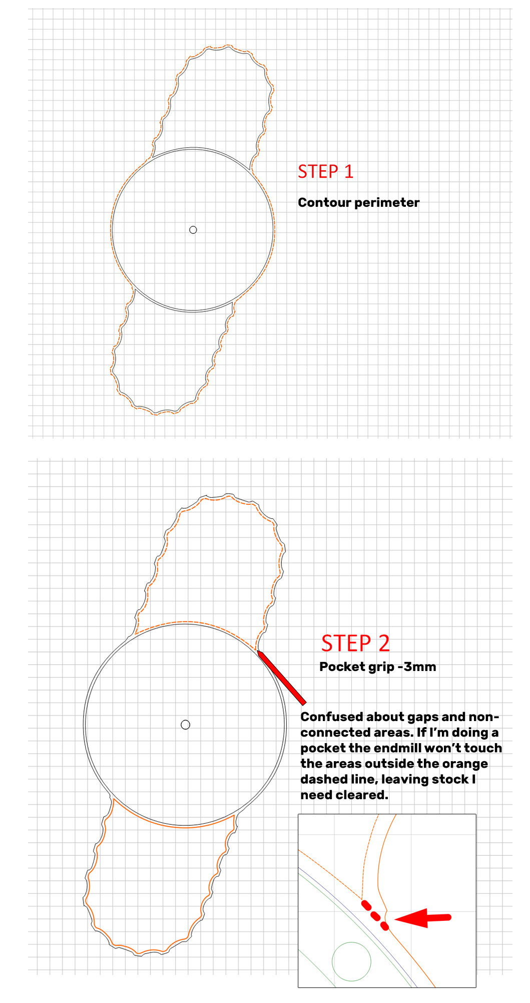
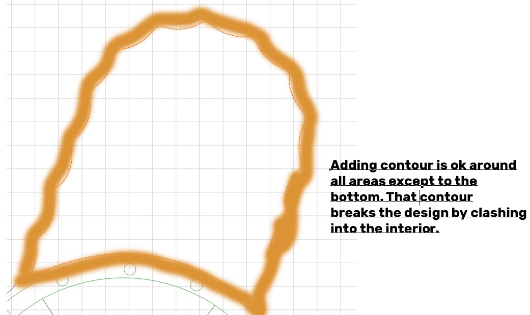
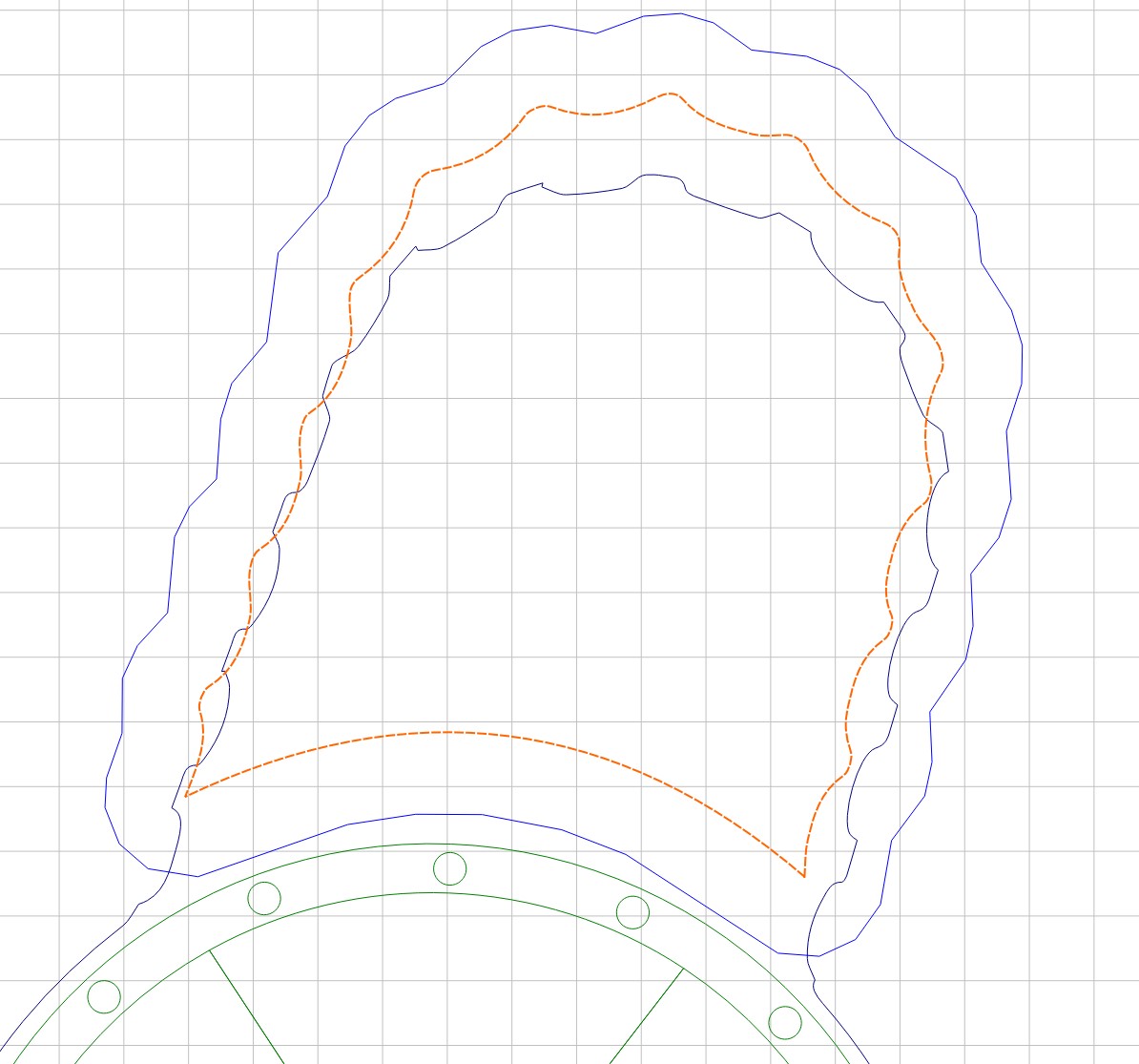
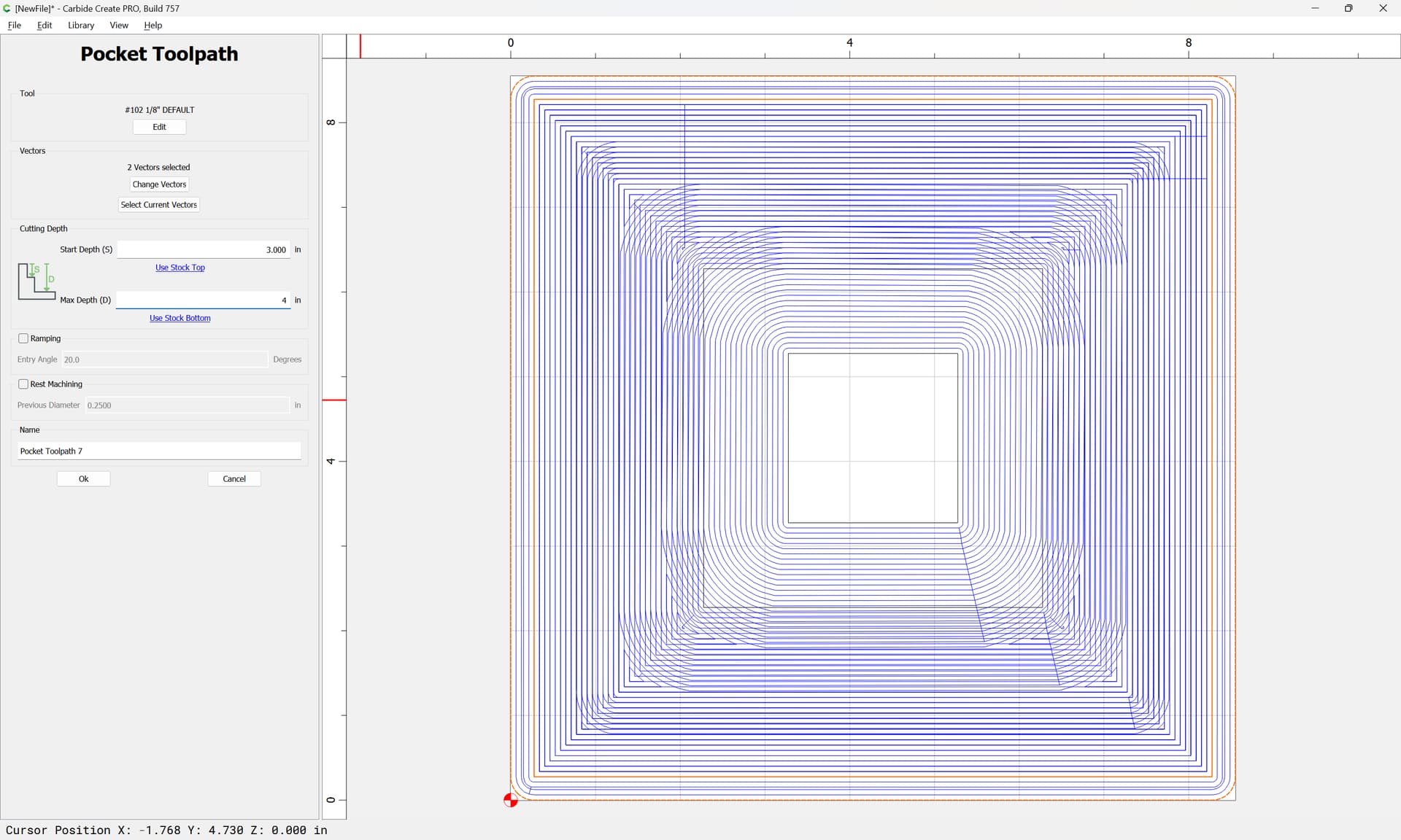
Here’s the current issue I’m facing. Running step 1 (contour path) is easy, but then once it comes to pocketing the gripper areas things get extremely confusing. I’ve been trying to make some kind of workaround but it’s not clicking what I need to do.
Things aren’t clicking for me. I don’t understand why an offset was added, or why the nodes were edited in the example. For me it would make sense to just create the shapes to be pocketed with capped ends (and correct channel dimensions). I think my brain maybe trying to cheat and find an easy solution instead of actually understand lol.
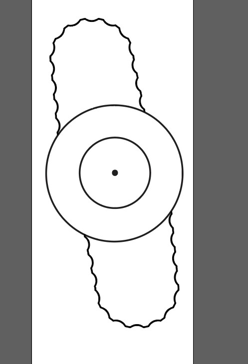
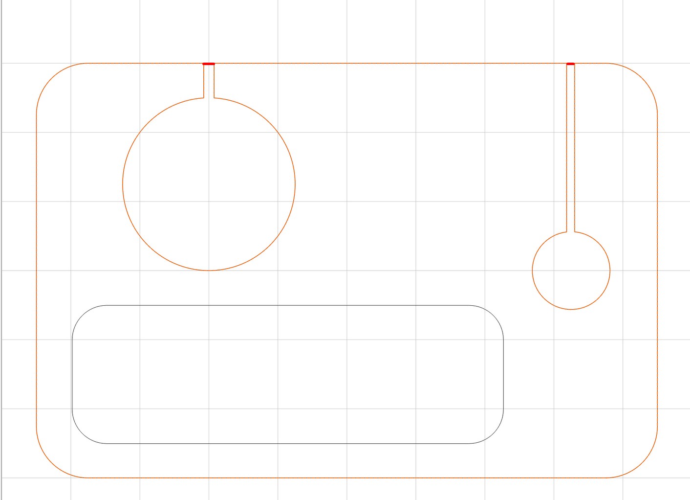
I took the path that defined the outline and combined it with a circle with the same diameter as your center to achieve the SVG I shared above. It’s not perfect because the diameter of the center portion on your original was inconsistent (not a perfect circle).
Machine a mirror imaged negative of this as a fixture, insert the part into it, the cut the first toolpath registered w/ the fixture to complete things.


