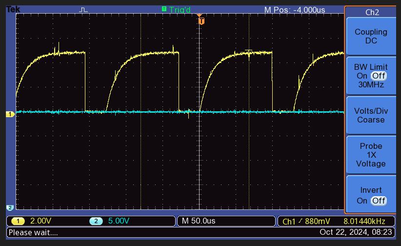
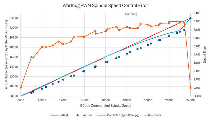
The speed accuracy of C3D’s $750 spindle isn’t so great as documented elsewhere on the forum. Kind of wish I had seen those posts before buying so I could have considered something else. That said, I’m not sure it would have mattered because the problem appears to be not the C3D VFD/spindle but rather the quality of PWM output from the Warthog controller.
Image below is output of the PWM signal from Warthog when disconnected from the VFD (thus removing any possible loading effects). Certainly not what one would expect to see from a proper PWM, but more like an RC filtered half-rectified signal that will undoubtedly lead to the nonlinearity one sees with the 9% speed sag vs commanded gcode. Kind of baffled about why they chose to do that.
Best I can do to correct this is to utilize a Python script as a PP (like example in the ZIP) to correct for this somewhat, but besides being a band-aid, it doesn’t work well above 20k rpm given the noisy signal and discontinuity that occurs right at the 24000rpm upper end.
spindlefix.zip (1.7 KB)
Only thought is to either handle spindle gcodes using a separate MCU (like a Teensy) processing g-code in parallel to the Warthog box and feed the PWM from there, or bypass analog signal conditioning and feed the PWM directly from the ICSP. I’m reluctant to do either given I’m still within warranty and already getting occasional spindle bearing noise (and not just a loose spindle plug collar) that I’m watching closely.
Because C3D offers no resolution, locks their lookup table in the VFD, and claims that speeds don’t matter that much I’m less than happy. My experience from lots of trial and error is that speeds actually DO matter when working with ColorCore HDPE and marine EVA foam as I do mostly. Minor tweaks in speeds and feeds are making the difference between good cuts and bad ones but it’s hard to run good experiments to tune this when you can’t trust the equipment.
Would much rather be making parts as intended than spending my time debugging the machine!

