Chapter 2 Deflection and Vibration
Why do we care?
There are two main reasons to care about deflection and backlash in the machine.
Ultimate accuracy
Whilst we can achieve some pretty-impressive accuracy with a Shapeoko, this frequently involves several rounds of cutting, measuring, fiddling with the CAM to incrementally approach the final dimension we require. This can be somewhat time consuming and make our CAD / CAM models more complex as we make the compensating adjustments.
If we take roughing passes to cut the bulk of the material and finishing passes to get to final dimension our deflection due to cutting load is minimal in the finishing passes. It should then only be backlash that prevents us from approaching the step size limiting precision of the machine.
Cutting speed
The second concern is cutting speed, when we cut, we generate forces, the machine needs to resist these forces and keep the cutter and workpiece where they are supposed to be. Deflection in the machine affects the cut, but more significantly, allows vibration to develop. In particular there are modes where the machine tends to resonate, these can build a positive feedback loop where the vibration periodically varies cutter engagement and therefore the cutting forces, reinforcing itself and increasing the amplitude.
In practice the impact of vibrations and resonances can vary from poor finish through breaking cutters, damaging the workpiece, pulling the workpiece loose or even damage parts of the machine.
So, deflection primarily limits the speed at which we can cut and potentially the quality of finish whilst backlash primarily limits our final accuracy.
Backlash, Slack and Deflection
First, what do we mean by the terms backlash, slack and deflection?
Backlash
Backlash is lost movement in the linear motion system where we request a change of direction. For a typical rack and pinion, ballscrew or leadscrew driven linear motion system we can visualise backlash as being like carrying a bowling ball in a box.
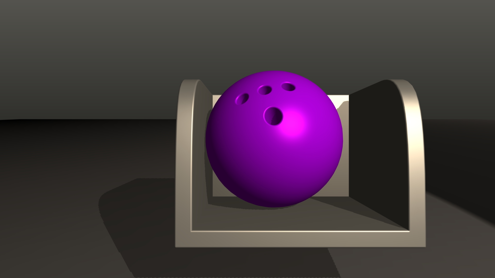
The ball is broadly constrained to go with the box, but each time we reverse direction we have to move the box far enough for the ball to hit the opposite wall before it follows the box change in direction.
On the Shapeoko backlash occurs through a different mechanism and presents slightly differently. Here is backlash on the X axis, we are measuring close to the belt to reduce the influence of other movements such as V Wheel deflection.
Slack
Slack is very similar to backlash in that it gives a range of positions the machine may be when no force is applied. The distinction, for our purposes, is that slack occurs not due to the drive belts but simply through slack in the mechanism such as the V Wheels which allow movements not controllable by the motors and belts.
Deflection
Deflection is where the machine moves from the requested position due to forces encountered whilst cutting (or by the operator). Some of this deflection comes from flexing parts of the machine, some of it comes from stretching the drive belts.
When cutting deflection can cause a couple of problems, first it can cause cutter engagement to be larger or smaller than we intended, affecting the cutting load. Second, and more of a problem on a light machine like the Shapeoko is that the machine can start to vibrate and resonate with the deflection of the cutting loads.
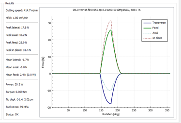
(screen capture from Millalyzer application)
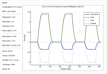
The graph shows some example cutting forces for a 6mm single flute cutter in 6061 Aluminium making a Shapeoko sized cut at 22kRPM, each rotation there is a spike of 32 Newtons on the cutter but the average forces are quite low. For the range of speeds and cutters commonly used on a Shapeoko the frequency varies from around 200Hz to 1.5kHz, this is a broad range of input to excite vibration and resonance modes in the machine. Here’s another for a 3 flute cutter showing the three impacts of teeth on the workpiece per revolution
Deflection, Vibration and Resonance
The major limit to cutting speed on the Shapeoko is vibration of the spindle or workpiece induced by cutting forces. It is rare to run out of spindle power or torque before encountering one of these vibration modes. Most users have experienced this when pushing their machine into too heavy a cut where small vibrations rapidly build up into large vibrations which are then difficult to suppress. When examining this system, not all our deflections are equal when it comes to vibration.
It’s worth taking a look at the vibration and resonance issues before moving into the deflection and backlash as these are the primary issue arising out of the machine deflections.
Basics of Vibration
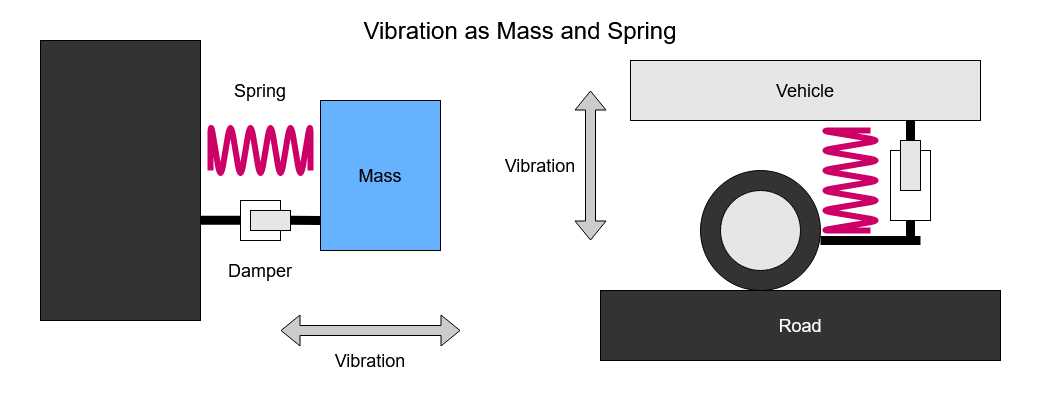
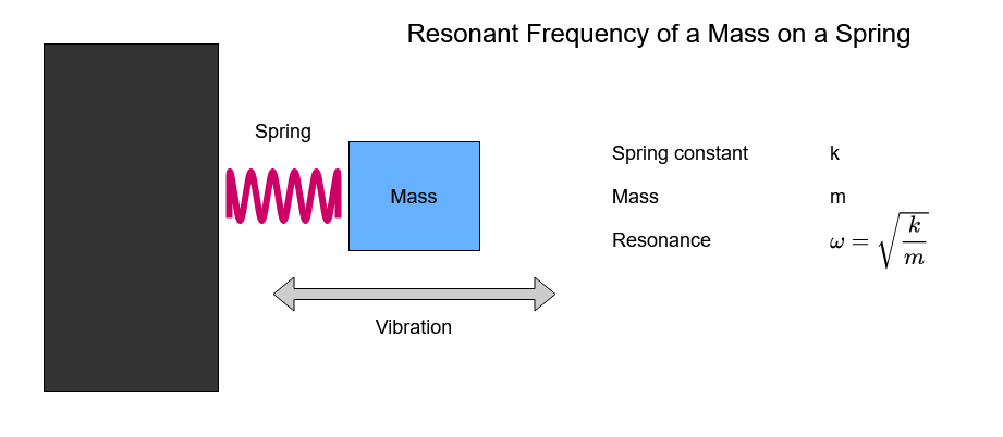
Before discussing the vibrations in machining let’s take a moment to define a few terms and describe what part they play. To think about the vibrations, consider a simple mass on a spring, like a vehicle on a suspension spring.
As the mass moves, the spring compresses and extends. The spring wants to be in the ‘middle’ so it works to reverse the movement. There is a frequency at which each mass & spring combination likes to move. The lighter the mass or the stronger the spring the higher that frequency.
There is usually some sort of damping taking place as well to reduce the movement. The greater this damping the faster the mass will stop moving when the force is no longer applied and the smaller the maximum amplitude of the movement if we continue to excite the mass at the resonant frequency. This is why old cars bounce up and down quite easily but new cars with working shock absorbers don’t.
Chatter, Vibration & Resonance
In traditional milling machines the phenomenon of chatter is relatively well understood. Machine, tool and workpiece deflections interact with cutting forces to excite a resonant vibration in the machine, thus producing the characteristic ‘chatter’ sound and other issues. Various rules of thumb exist to avoid or manage chatter such as keeping tool deflection due to cutting forces below 0.001” or plotting stability lobe diagrams of your machine and tool combination.
This is not a simple process and there is a range of ways in which your machine can vibrate in these undesirable modes and affect the cutting performance.
At one end we have high frequency vibrations, in the range of our high speed spindles’ rotational speeds where relatively small masses, such as cutters or parts of the workpiece, vibrate on very stiff ‘springs’ such as the deflection of the carbide cutting tool or a wall in the workpiece.
At the other end we have lower frequency vibrations where relatively heavy parts of our machine assembly vibrate against less stiff springs. One example of this is the Z carriage and spindle assembly vibrating on the drive belt ‘spring’.
Vibration Interacts with Cutting Forces
When the machine is cutting we have a series of things going on, the cutter is rotating at a target speed, being fed through the workpiece at a feed rate and has some depth (axial) and width (radial) of cut, all adding up to the cut we are taking (or trying to take).
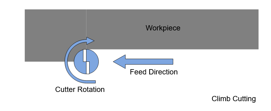
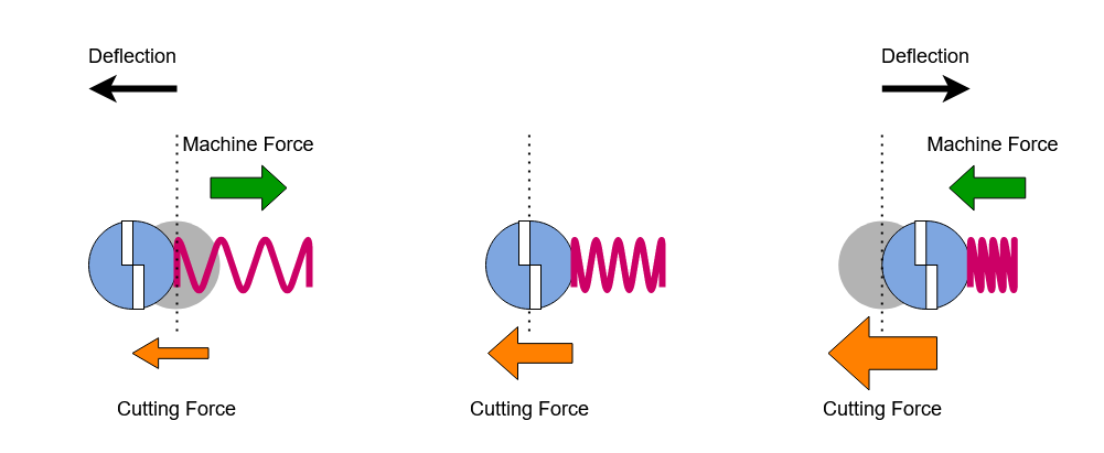
Once this cut starts, the cutter produces forces between the spindle and workpiece as it cuts, these forces on the cutter are shown, simplified, for a climb cut below. These would be inverted for conventional cutting.
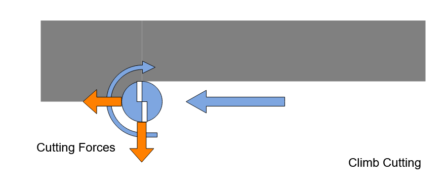
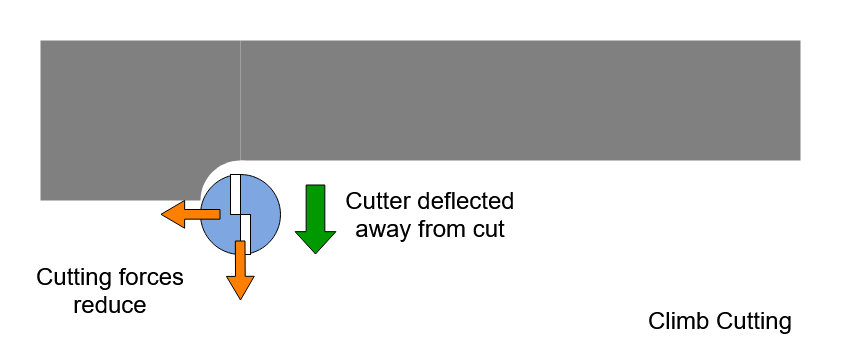
These forces inevitably deflect the cutter and workpiece some amount. When the cutter deflects away from the cut, as caused by the cutting forces above, the engagement reduces and thus the cutting forces. This machine then tends to spring back into the cut. If the workpiece deflects we have the same outcome.
When the machine swings back and deflects the cutter further into the cut, the engagement increases and the cutting forces increase, in this case pushing the cutter back away from the cut.
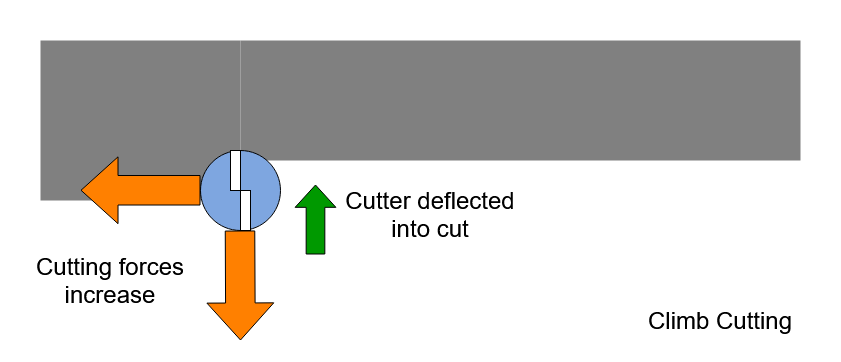
So we have a system where the deflecting forces are affected by the deflection. If this happens at a frequency at which the tool, workpiece or machine can resonate then we have a positive feedback system which can rapidly achieve a large displacement. The problem with these resonance modes, especially when they have little damping, is that once excited they can be hard to escape. They can develop a lot of energy and will continue to feed themselves with energy whilst the cut continues.
There is a famous video of the Tacoma Narrows bridge demonstrating why resonance can be bad.
Worse, vibrations also leave variations in the cut surface which may trigger the same vibration on the next pass of that cut. Returning to our vehicle analogy, once the road starts to washboard, it can be very hard to get away from that vibration.
Shapeoko Resonance
There are various well understood methods and tools for larger machines, from test cuts through to specialised test hardware which measures the cutter and machine resonances. These identify problem frequencies and provide feeds & speeds or charts to avoid them. This knowledge is less well developed for ‘hobby grade’ machines.
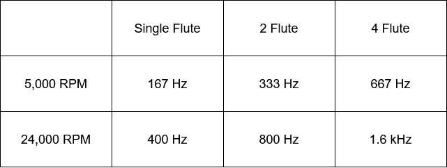
So, what sort of frequencies might we expect on a Shapeoko? For vibrations triggered directly by the cutter rotation at spindle speeds we’d expect to see frequencies somewhere in the range of 200Hz to 2kHz.
Vibrations at these frequencies are generally not visible to the naked eye, when you see a speaker cone moving it is bass frequencies, not midrange.
However, in addition to simple spindle frequency vibration we also have the lower frequency modes which are not directly responding to spindle speeds but instead build up in the machine as resonance. Going back to our simple mass on a spring, we can do some simple calculations to find out what sort of frequencies we might see on the Shapeoko.
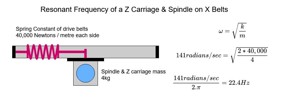
Let’s take one element of the Shapeoko, the Z carriage and spindle and isolate it from the rest of the machine. We will assume the spindle is deflecting left to right on the X axis rail opposed by the spring of the drive belt. Taking the values from my machine we get an approximate resonant frequency of 22Hz which is consistent with the visible resonance modes I have observed on my machine.
This vibration has some damping, primarily the rolling resistance of the V Wheels. This is perhaps another reason why high V Wheel pretension seems to help the machine?
To try to improve this performance, we might add mass, say a water cooled spindle instead of a trim router. Unfortunately, the outcome is more complex. The additional mass lowers the resonant frequency and increases the amplitude when the resonance does occur. However, at frequencies above the resonance it will reduce the amplitude of vibrations.
Digging a little further we find the source one of the large differences between the SO3 and the XXL machine. Taking the X beam rigidity for the XL and XXL (which is addressed later on) and using this as the spring for the Z carriage assembly vibrating backward and forward;
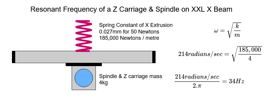
We see that we have a resonant frequency of about 34Hz. However, if we take the standard size SO3 machine with the shorter X beam, we have a much smaller deflection for the same force;
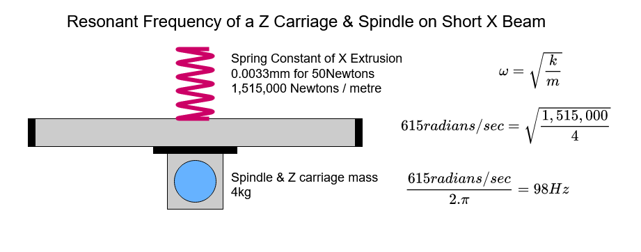
This higher spring constant gives a resonant frequency almost three times higher than the long X beam and suggests that the trigger feeds and speeds for this mode would be quite different on the standard size machine.
Deep vs Wide Cuts
One common observation about the both the Shapeoko and Nomad machines is that to achieve the maximum cutting rate (MRR) one should use a shallow but wide cut instead of a deep but thin cut;
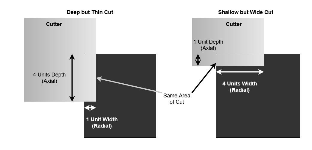
We know that in a resonance mode we have feedback between deflection and cutting force. Taking two cuts with the same cutter engagement, one deep, one shallow. If we allow both cuts to deflect horizontally by the same amount, we see that the shallow cut only sees 20% extra engagement whilst the deep cut sees double the engagement and therefore cutting force.
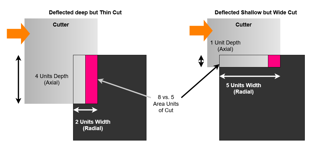
Also worth noting here is that with cutters with a helix angle (i.e. not straight flute) the deeper cuts will also create significant vertical forces to excite the coupled Z and Y nodding deflection (again more on that later).
Shapeoko as a System
We can look at the main parts of the Shapeoko as a connected system of masses and springs.
Here is a simplified diagram which illustrates some of the main components in which I have measured deflection. On the left we have cutting which creates force between our workpiece and cutter, the forces and their resulting deflections and vibrations then travel to the right, through the components of the machine until we reach the mounting base.
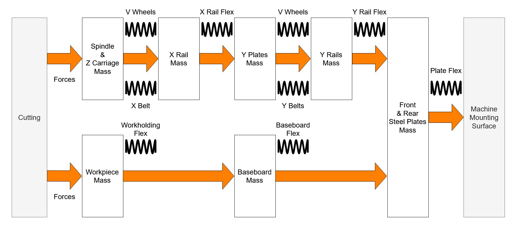
This system is unfortunately quite complex to model and analyse, however, modern computer simulation tools can provide some excellent insight into this. Hopefully somebody with those skills will have something to say about that.
What we can do now is look at this system and identify that we have several large sources of deflection close to the cutter and that these are likely to be our major targets to reduce slack, improve rigidity and, if possible, increase damping;
- Z axis and spindle rotating due to V Wheel radial deflection
- Z axis and spindle nodding due to V Wheel axial deflection
- Z axis and spindle translating left-right against belt tension
- On the XXL machine, the bouncy baseboard