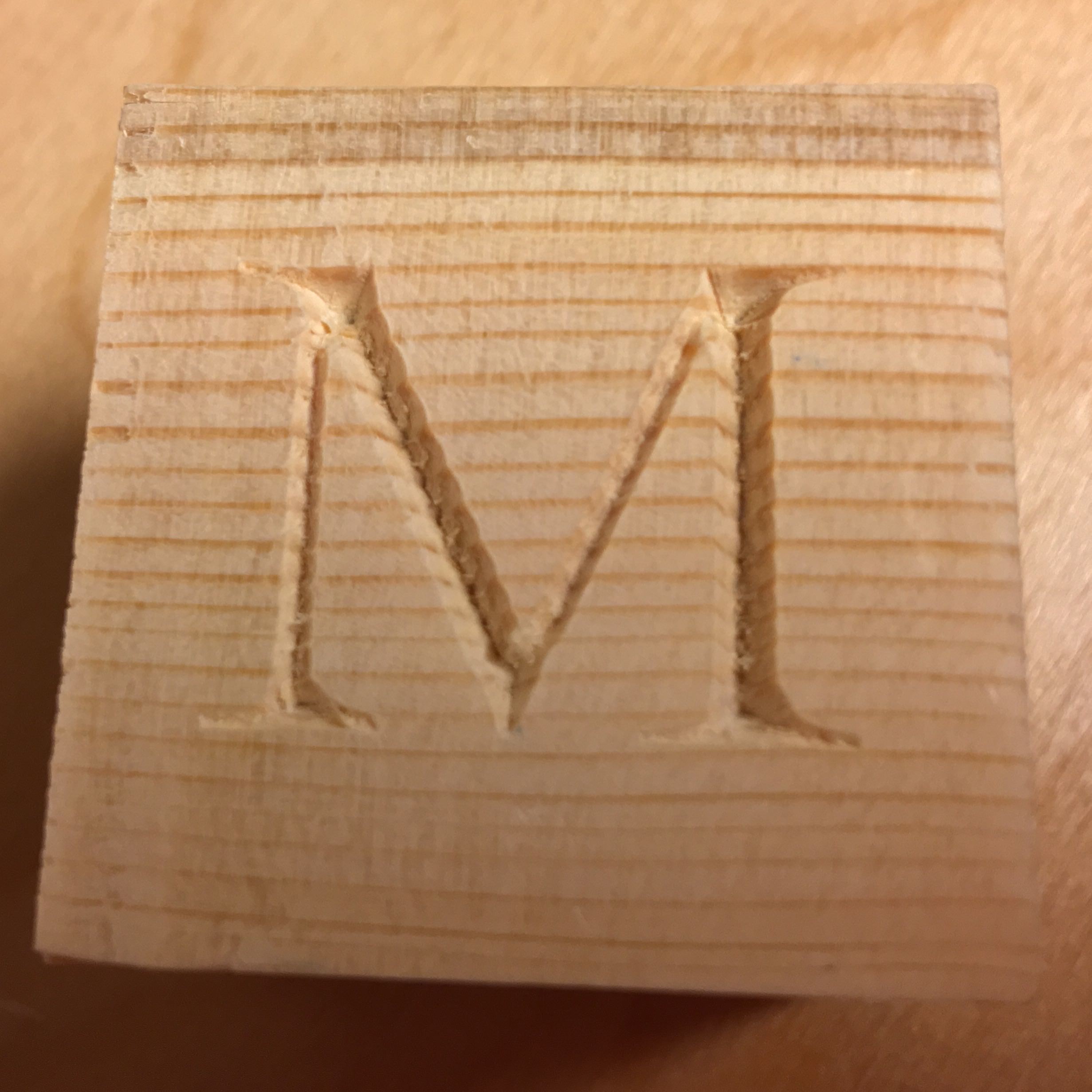
I’m starting to use my Shapeoko 3 to do some engraving and I’m finding that the quality I get is not the same that I see from other users. I’ve tightened up my Z axis plate (which had a little play) and now it slides smoothly without any play and the quality has increased a lot but I’m still getting the following two problems. This is better explained with images:
In the above image, you can see that the borders of the letters are bumpy. Almost like every time the cutter ran into the wood’s grain, it shifted a little. It doesn’t happen on all the cuts but it is mostly visible in the upwards diagonal cuts. Also, the bottom of the V-groove is not tidy. Some debris is left after the cut which can’t be vacuumed; it’s still attached to the wood.
The cutter I’m using is brand new and these two were literally the first cuts it made so I doubt it is dull. The other V bit I have shows the same kinds of cut defects so it must be either a GCode programming error or something I messed in my machine’s tuning.
For the above-mentioned test, I used douglas fir 1 1/2" cubes. For software, I used Carbide Create and Carbide Motion.
You brought up the first two things that came to mind for me, namely the bumps matching the wood grain and the possibility of a dull cutter. You might want to try a different g-code sender, like UGS, just to eliminate that from the equation. Maybe feeds and speeds are an issue here?
Agree that Pete (@Winters636) is on the right track w/ feed and speed.
That said, Fir is not the greatest stuff to cut for holding a crisp edge — additional things to try:
roughing clearance and a finishing pass — you could fake this out by holding initial Z zero higher by a bit, then lowering it for a second pass
sharper / HSS endmill — best practice here is carbide for a roughing pass, then finishing pass w/ a nice sharp HSS endmill
a hardwood w/ a finer grain which will hold detail better.
a different software program to generate the paths — I doubt F-engrave would be better, but the Vectric folks are supposed to have well-optimized CAM for this which results in crisper files
I’m using a DW611 at it’s lowest speed setting (1).
Depth per pass 6.908mm
Stepover: 5.715mm
Feed rate: 100mm
Plungerate: 80mm
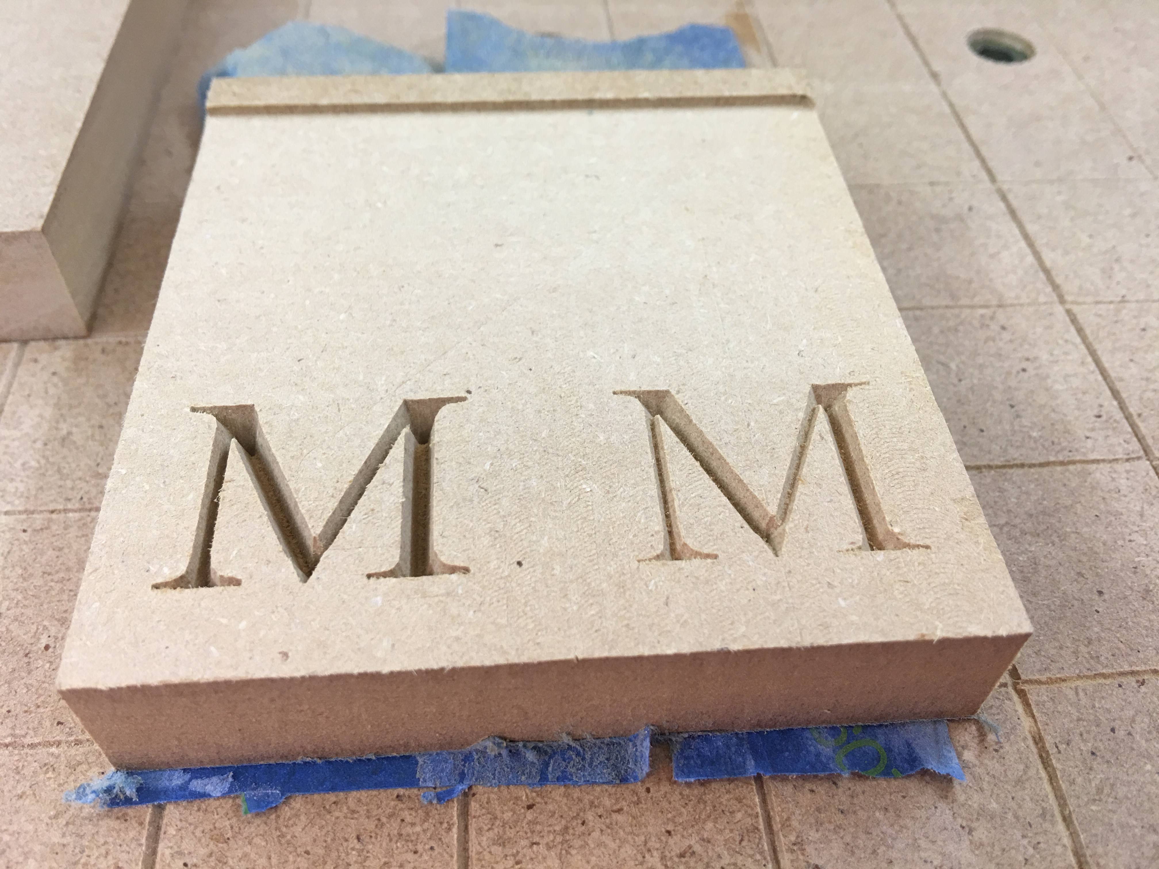
Wood choice: Hmm… I suspected douglas fir wasn’t a good choice. I was so fixated on this issue that I didn’t think of testing the cut on MDF.
roughing pass, then finishing pass
I haven’t had much luck with carving with two bits. To be honest, I haven’t tried it after installing the homing switches. I need to study the coordinate system in Carbide Motion better (I’m not always sure which coordinates I’m seeing).
Changing tools is explained pretty well in the following tutorial. After homing then jogging to where you want your job’s origin to be - then zeroing all - you can always get back to that position after a tool change by clicking Rapid Position button. You have to reset the Z origin though because the tool height will probably be different. After you’ve done it once it should become clear.
I would first look into trying another material. One of the best things I have found to clean cuts is a wire brush (just a quick tip for future) Also what bit are you using? It almost looks like it’s stuttering, but I’m guessing it’s just grabbing and pulling more then cutting clean which would mean either feed and speed or sharpness of bit or a combination of both.
You should be going much faster then 100mm I’m guessing for a wood. with maybe 1.5 on the router setting you should be nearly at 1524mm if you meant inches then it should be closer to 60 ish plus or minus 20. I use 60 IPM for most of my VCarve stuff with good success rate. May slow to as much as 40 or speed as much as 80 depending on how the material goes.
The cut is much better though the shape is so-so. This is probably due to the tool path generated by Carbide Create. As suggested earlier in this thread, a software dedicated to carving will surely yield a nicer shape.
But yeah, douglas fir didn’t seem like a good choice for this kind of cut.
Based on that image it would appear to me that one of 3 things is wrong.
This picture is a clear indication that the PATH is cut too shallow. Here are some things to think about.
The Z height is set incorrect (When zero was set it was a bit too high above the material)
-This can happen although not often the issue something to remember
The angel of the bit is slightly less then what you entered in the software.
–I guess this depends on the source quality of the bit but if it’s less then the cut would not be deep enough.
The Z belt may have skipped on the first down cut.
–If this happened the rest of the cut would be shallower then it should be.
Although none of these seem obvious, I’m betting that it’s one of these 3 because the bottom line is the cut is shallower then it should be and that points to the above 3 possibilities.
I wouldn’t put it past the V-bit not being a true angle, I have had a few Chinese ones as much as 2 degrees off!!! Of course you would need a sine block to check it but just be aware if it is off it will not clear as much as it should.
@rogwabbit I’m absolutely sure that 1 and 3 haven’t happened but 2 could easily be the problem. I bought these bits from Easel (https://www.inventables.com/technologies/bit-set-for-v-carving) and they could easily have the wrong angle. I don’t have anything to measure this other than the digital angle finder that I use with the table saw. I’ll make some kind of jig to measure this though I don’t expect it to be very precise.
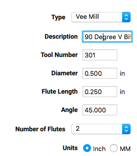
The other place that I could have fudged the settings is in Carbide Create itself:
Somewhere in the video tutorials it said that the Angle setting should be half the actual bit angle. Maybe if I play with this number I could do some test cuts and find the sweet spot for this bit.
Based on the comments on this thread, looks like the 30 degree cutter was more closely up to spec and the 60 not quite (but much better than my other 60 degree one that I tried on the first tests)
I have found that it is always important to test carve in MDF just to make sure all is o.k. Secondly, I had the same results as you when I used a 60 deg bit. Changing to a 90 deg bit using Oak made a big difference. Most of the time I use the suggested rates set in the VCarve portion of Carbide Create and it seems to work well. Pine, and Poplar aren’t as good for lettering it seems. A lacquer coat before cutting helps some of the splintering but makes it necessary to sand it off so your final finish is not goofed up.
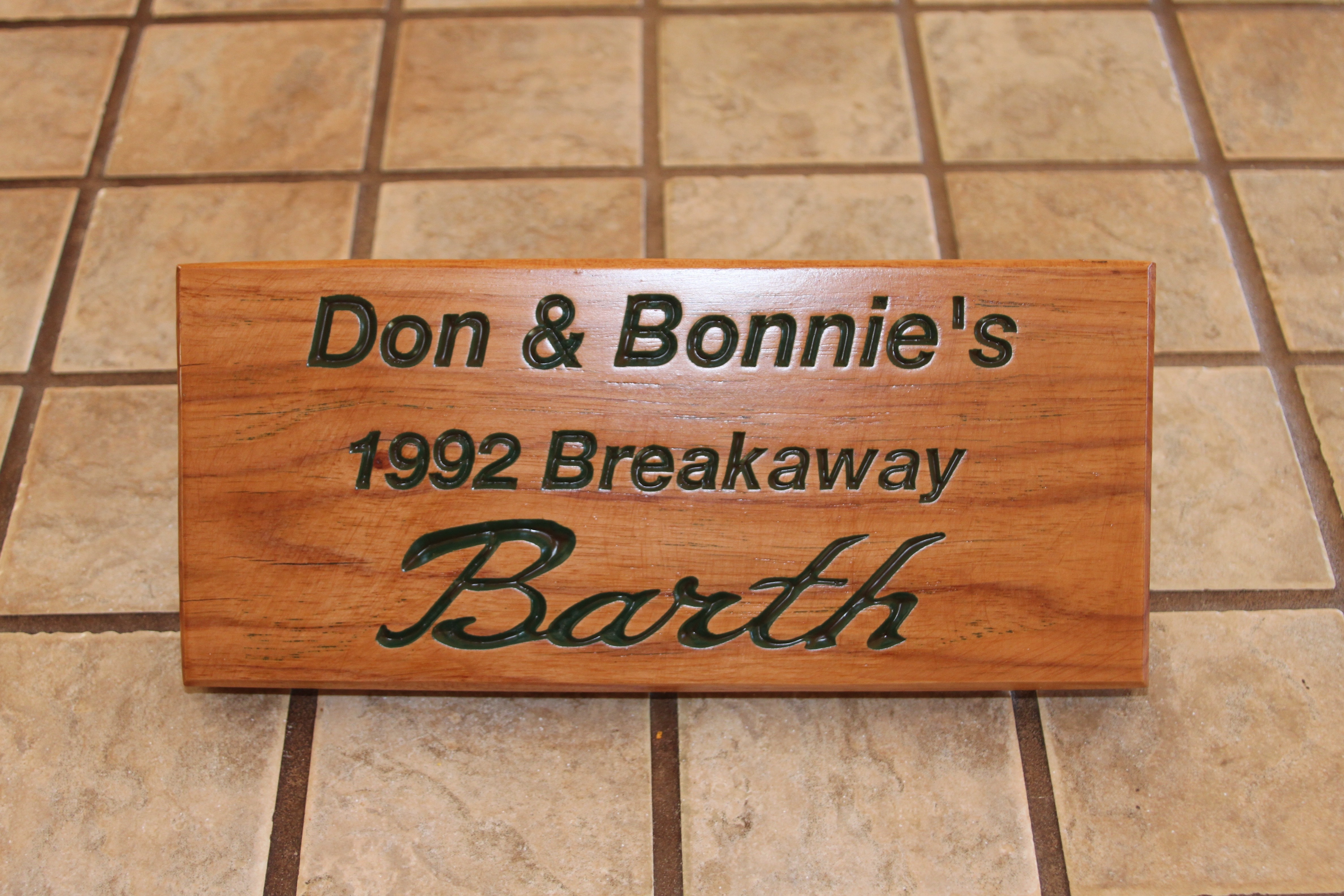
Here is a sign that I made using Red Oak. It is about 6" x 12". The Barth logo was imported into Inkscape then the .svg file was brought into Carbide Create for text insertion. I then painted the surface to color the letters, sanded it all off and finished with one of those one step stain/finish products.
Take your router bit and slowly lower it into a material at a known distance.
For instance set Z = 0 at the top of the material and then turn it on and slowly move the Z axis into a scrap material to any known distance shy of the full diameter of the blade but record the distance you moved the Z axis down.
Now measure the top of the hole as carefully as you can (it doesn’t matter if it’s mm or inches as long as its the same units as Z Depth)
Now the fun part open up calculator on your computer and make sure it’s in degrees and scientific mode.
Enter the Radius of the top of the hole (This is 1/2 of the measured distance)
divide that by the known z depth
Then use the tan-1 function
Then double that and that should be the angle of the bit.