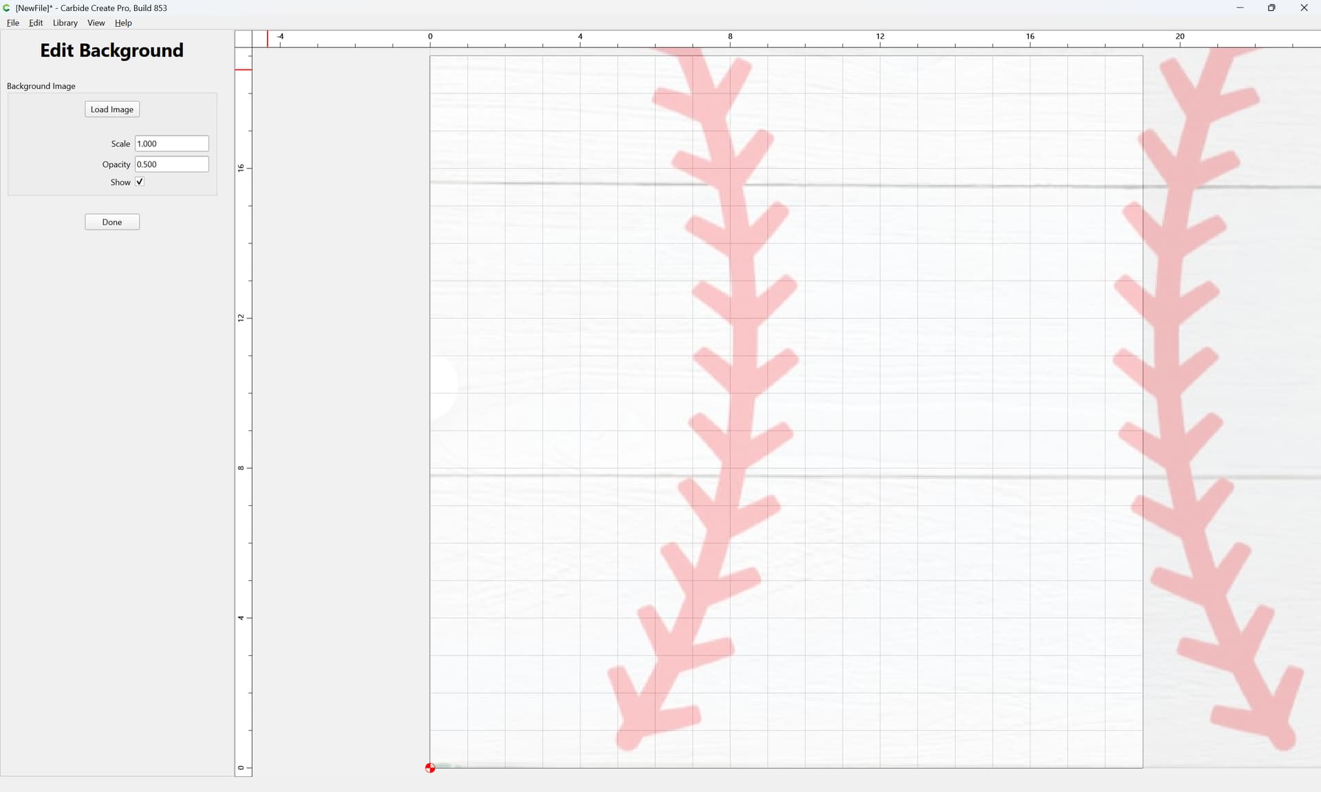
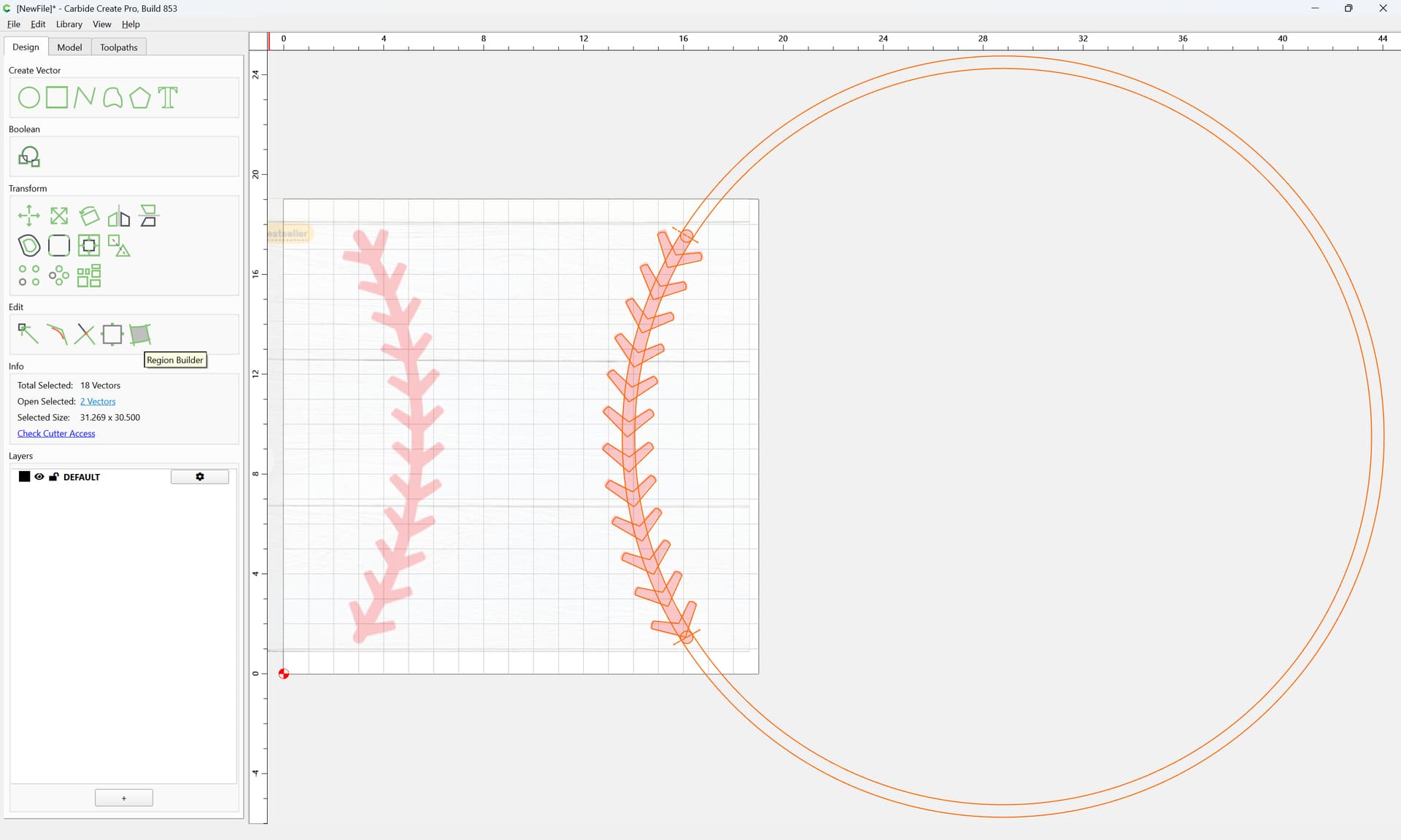
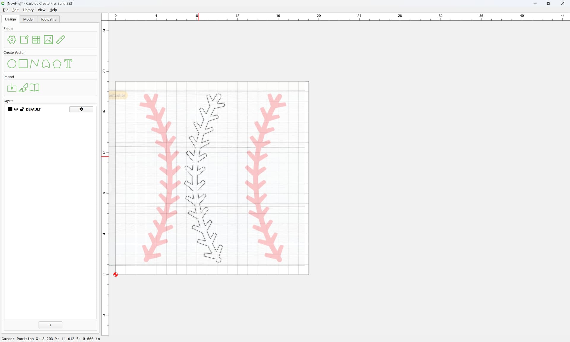
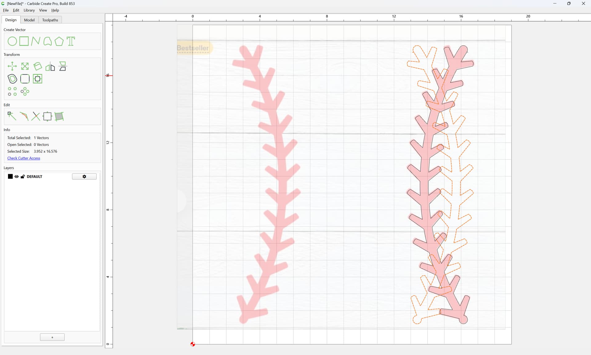
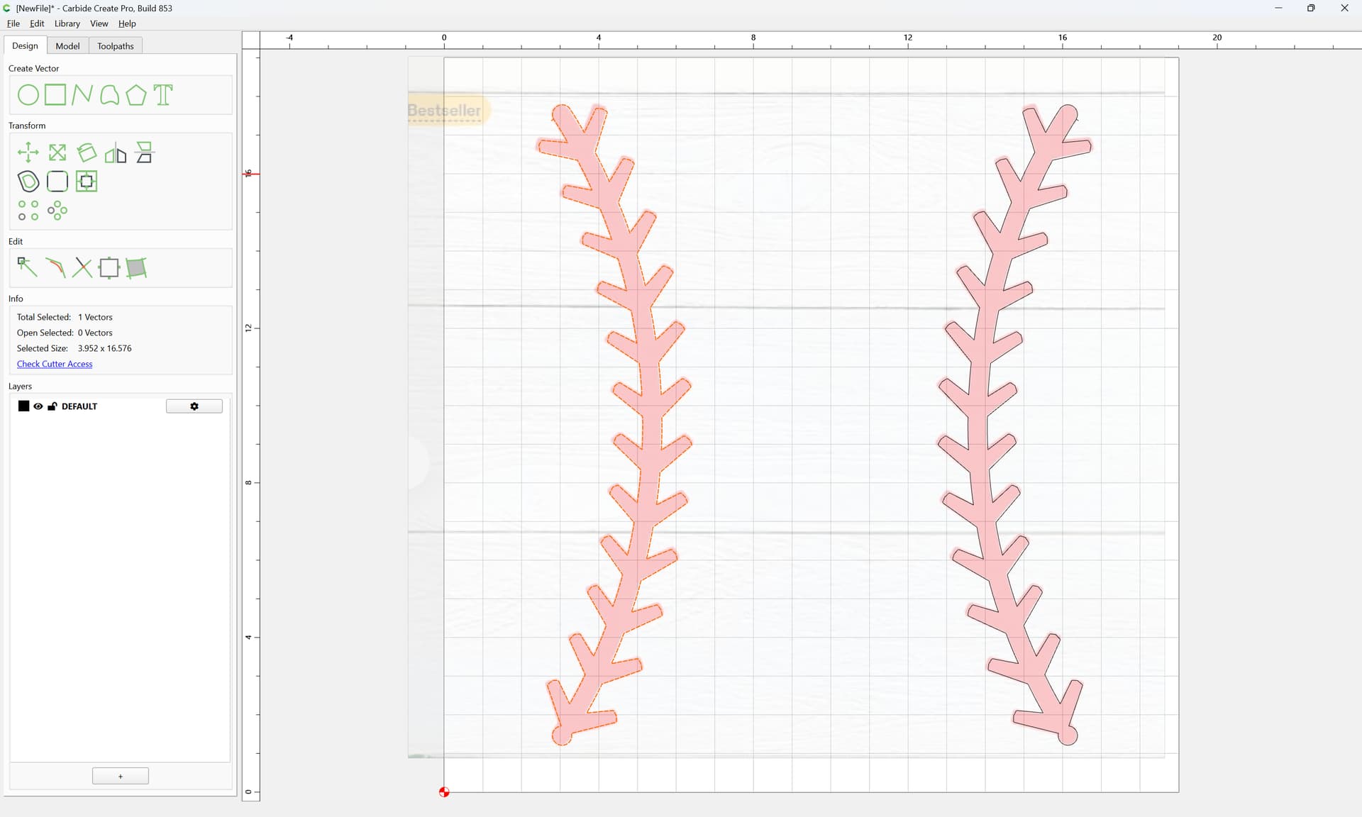
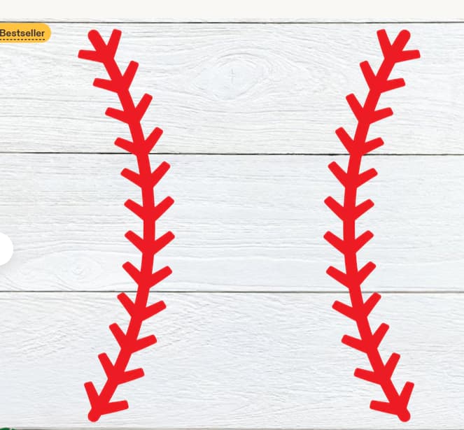
I AM TRYING TO PROGRAM TO PUT A SIMILAR STITCH PATTERN ON A 19" X 19" PIECE OF WOOD TO MAKE A HOMEPLATE FOR MY GRANDDAUGHTER. I CAN NOT FIGURE IT OUT
TOO NEW AT THIS
I AM TRYING TO PROGRAM TO PUT A SIMILAR STITCH PATTERN ON A 19" X 19" PIECE OF WOOD TO MAKE A HOMEPLATE FOR MY GRANDDAUGHTER. I CAN NOT FIGURE IT OUT
Stitches.c2d (76 KB)
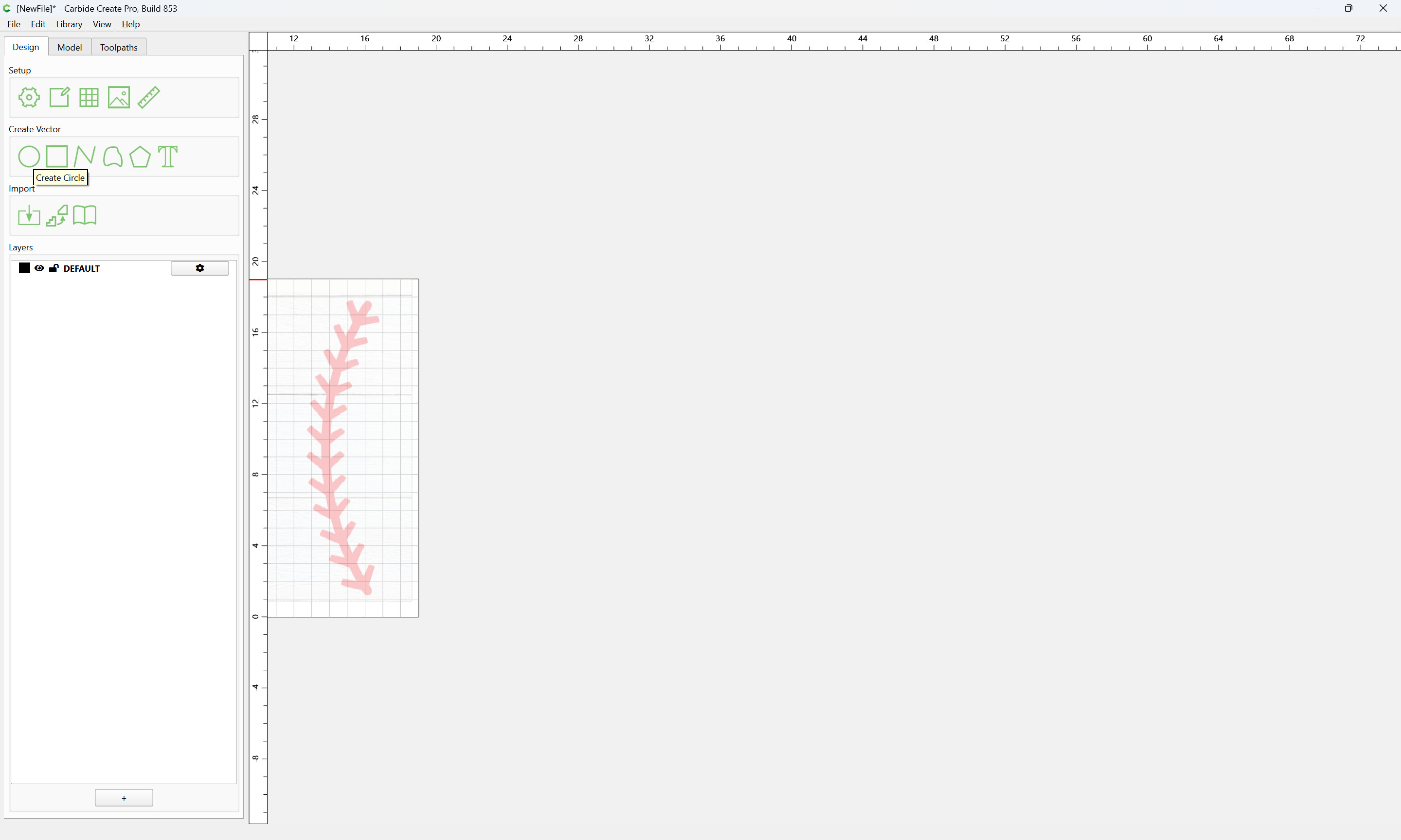
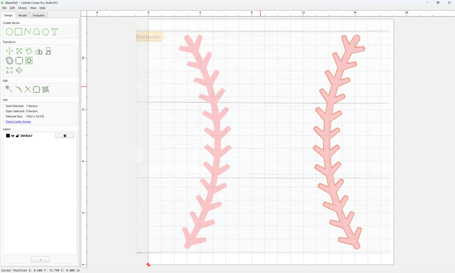
This is a straight trace from Carbide Create Pro. some paths had o be modified. Also understand that I didnt “clean” the path up.
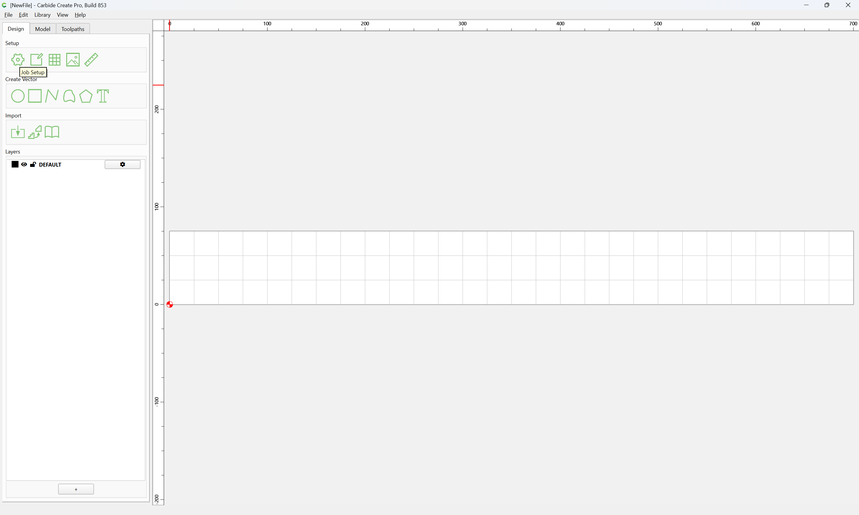
Launch Carbide Create:
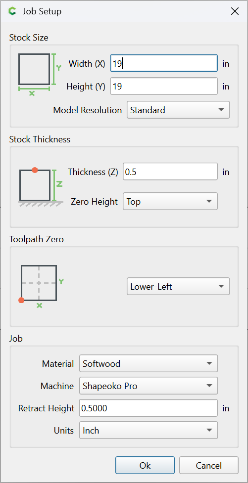
Job Setup:
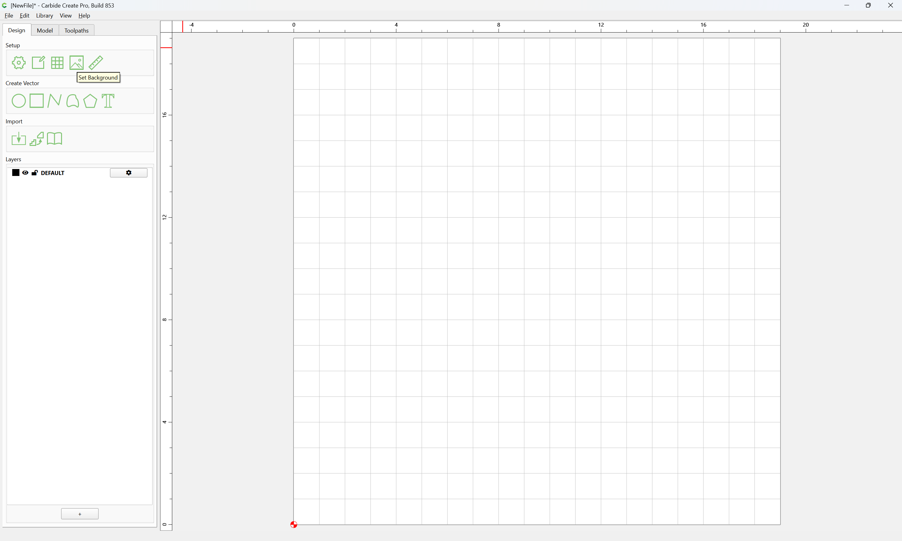
enter the appropriate dimensions, Ok
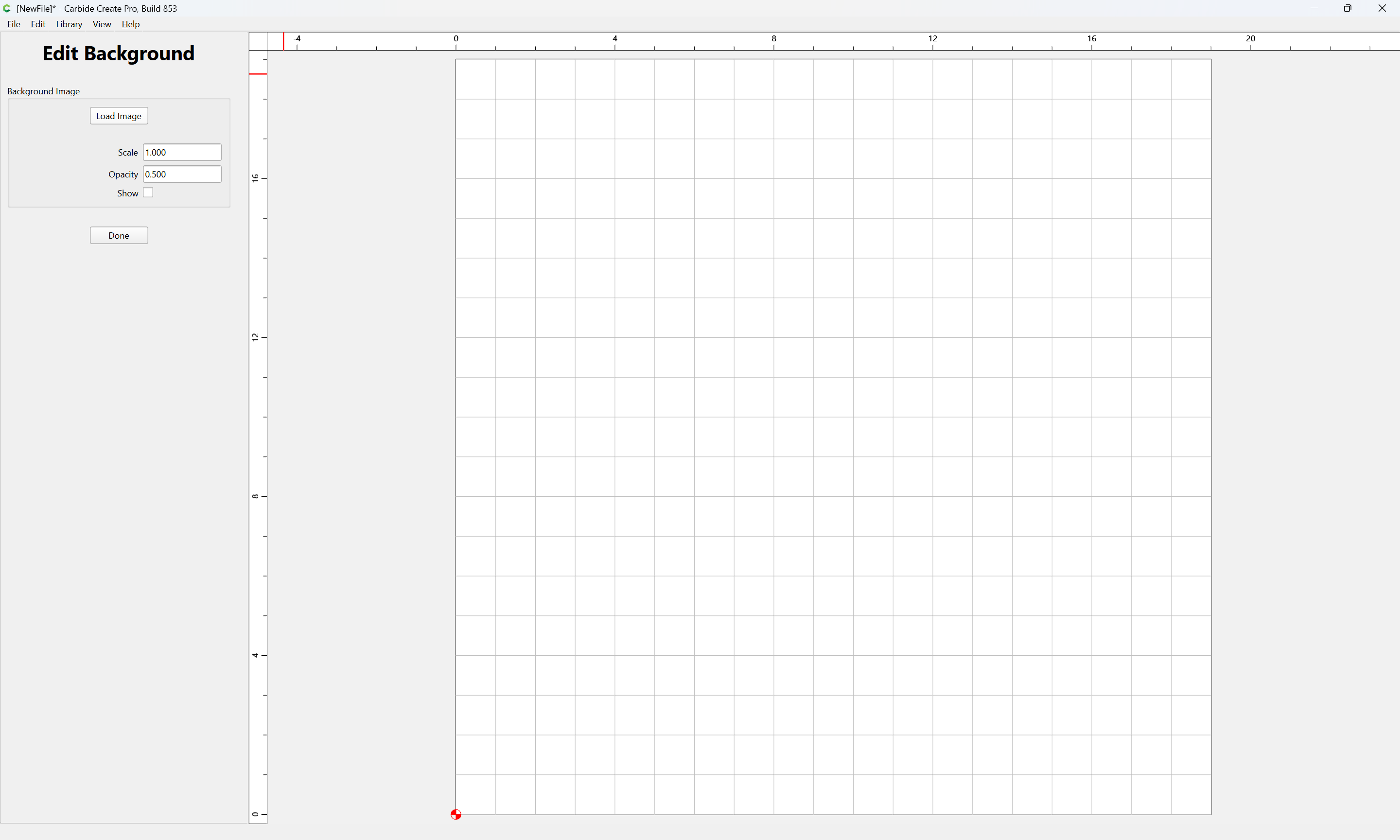
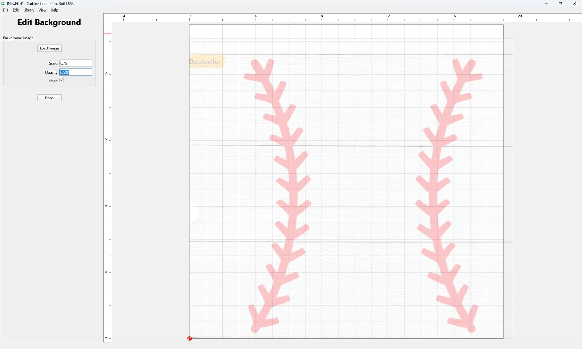
Set Background:
Load Image
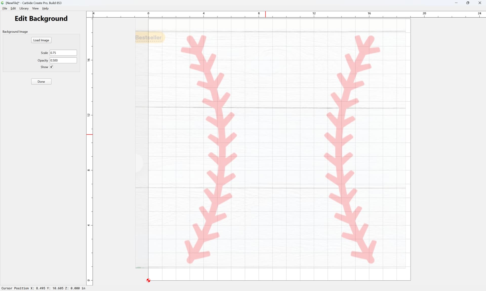
Adjust as desired:
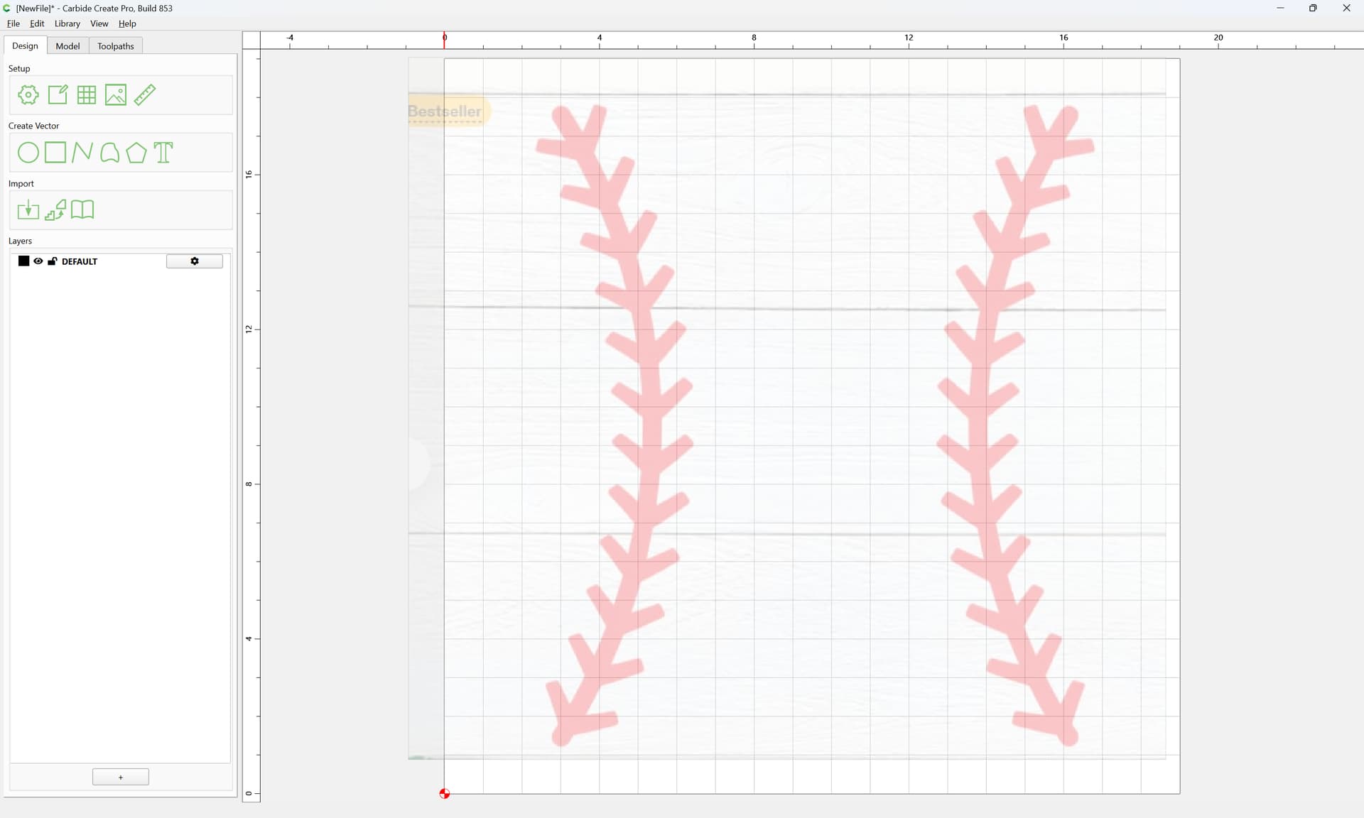
Done
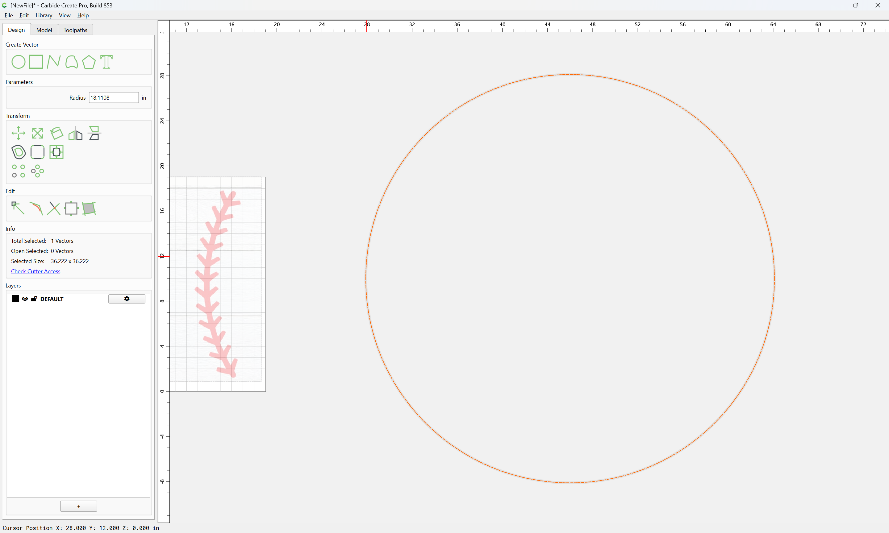
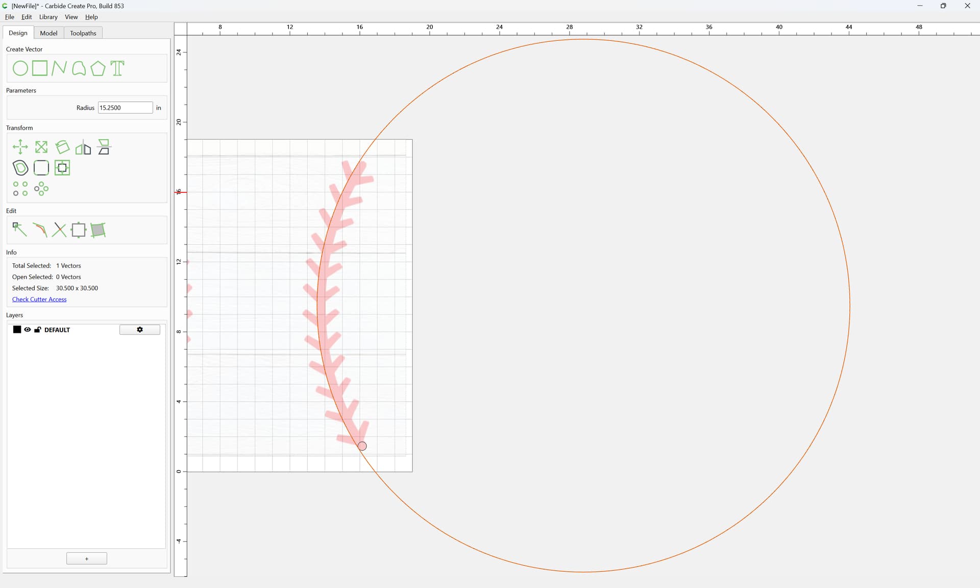
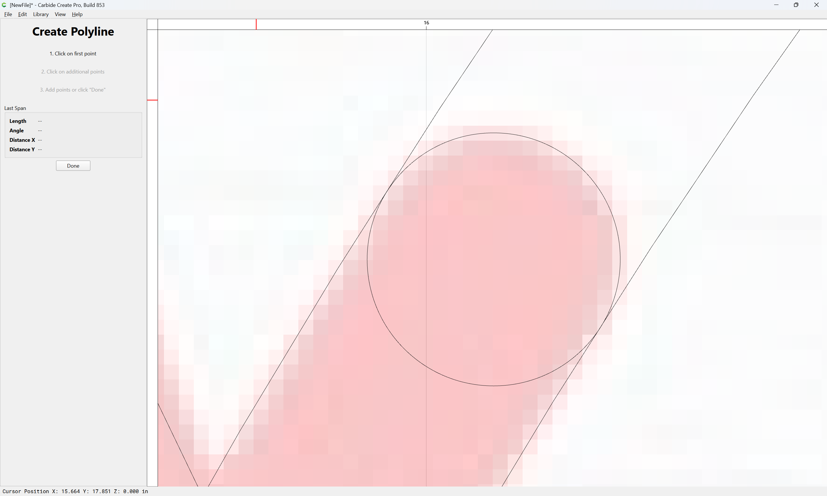
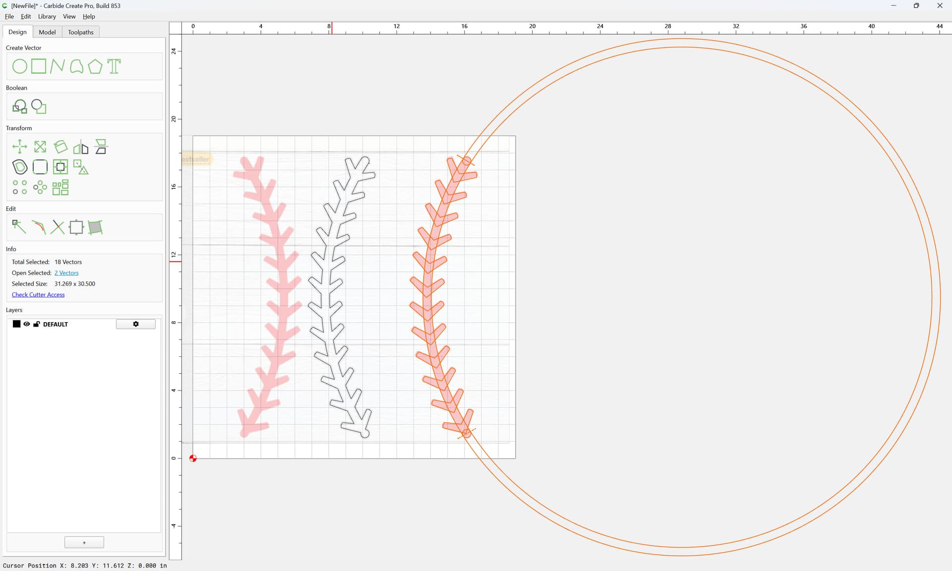
Since the design looks to be a part of an arc, zoom out:
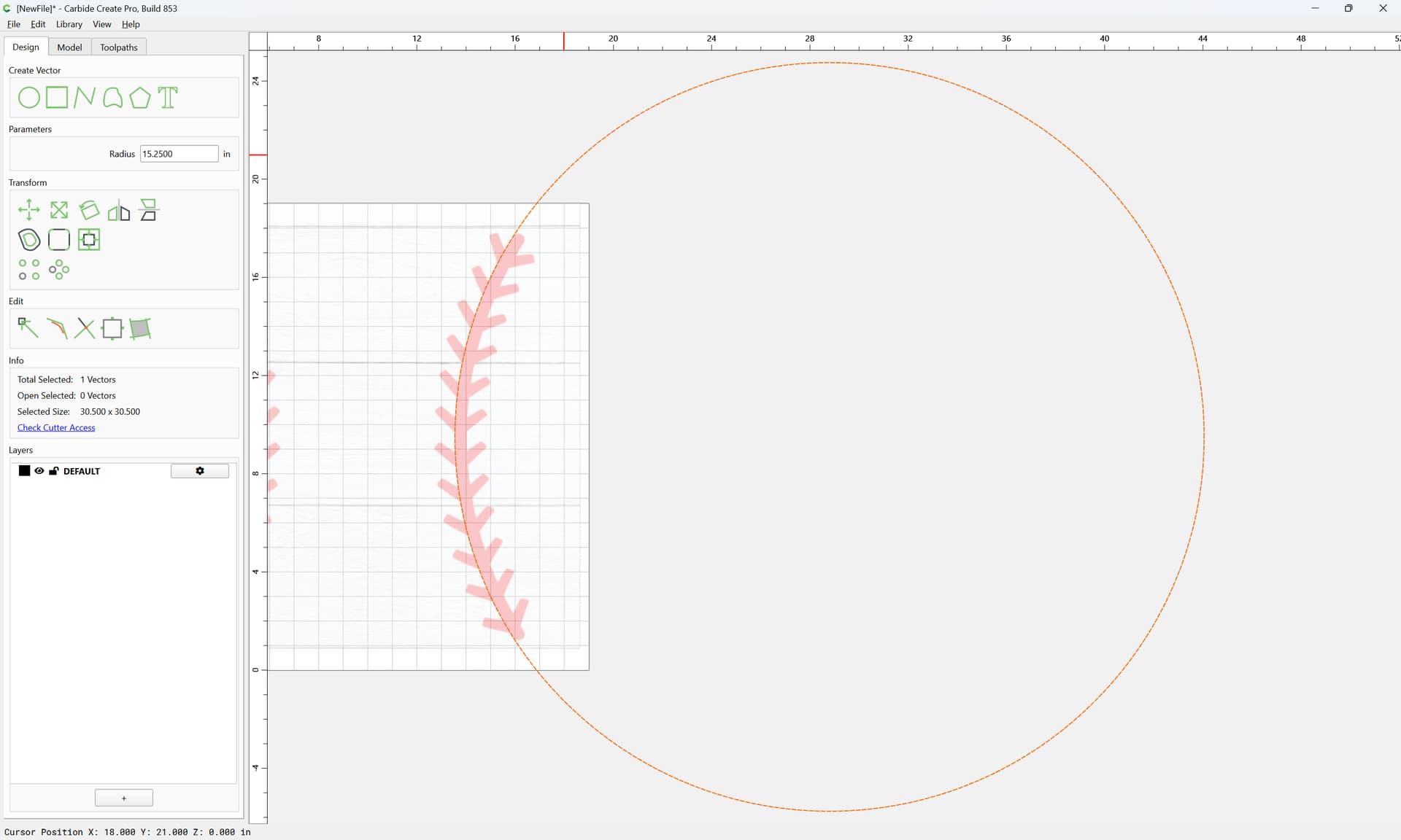
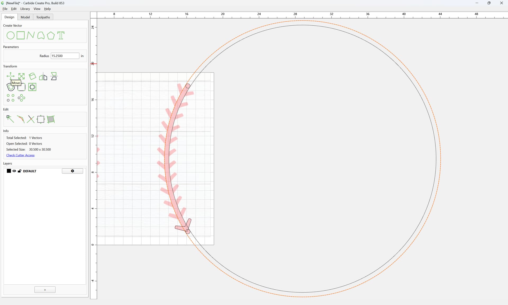
and draw a circle which coincides with one edge:
Adjusting as necessary
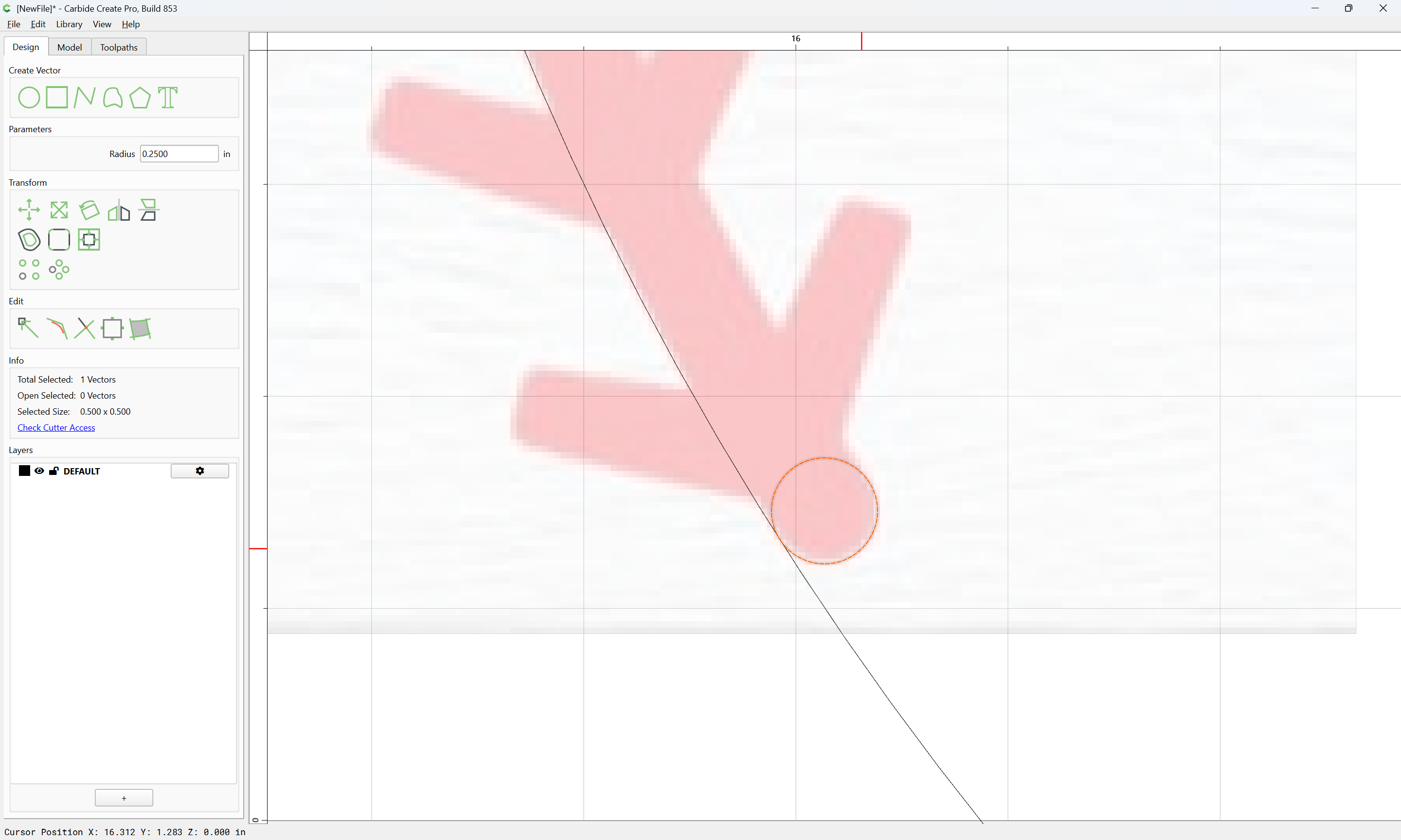
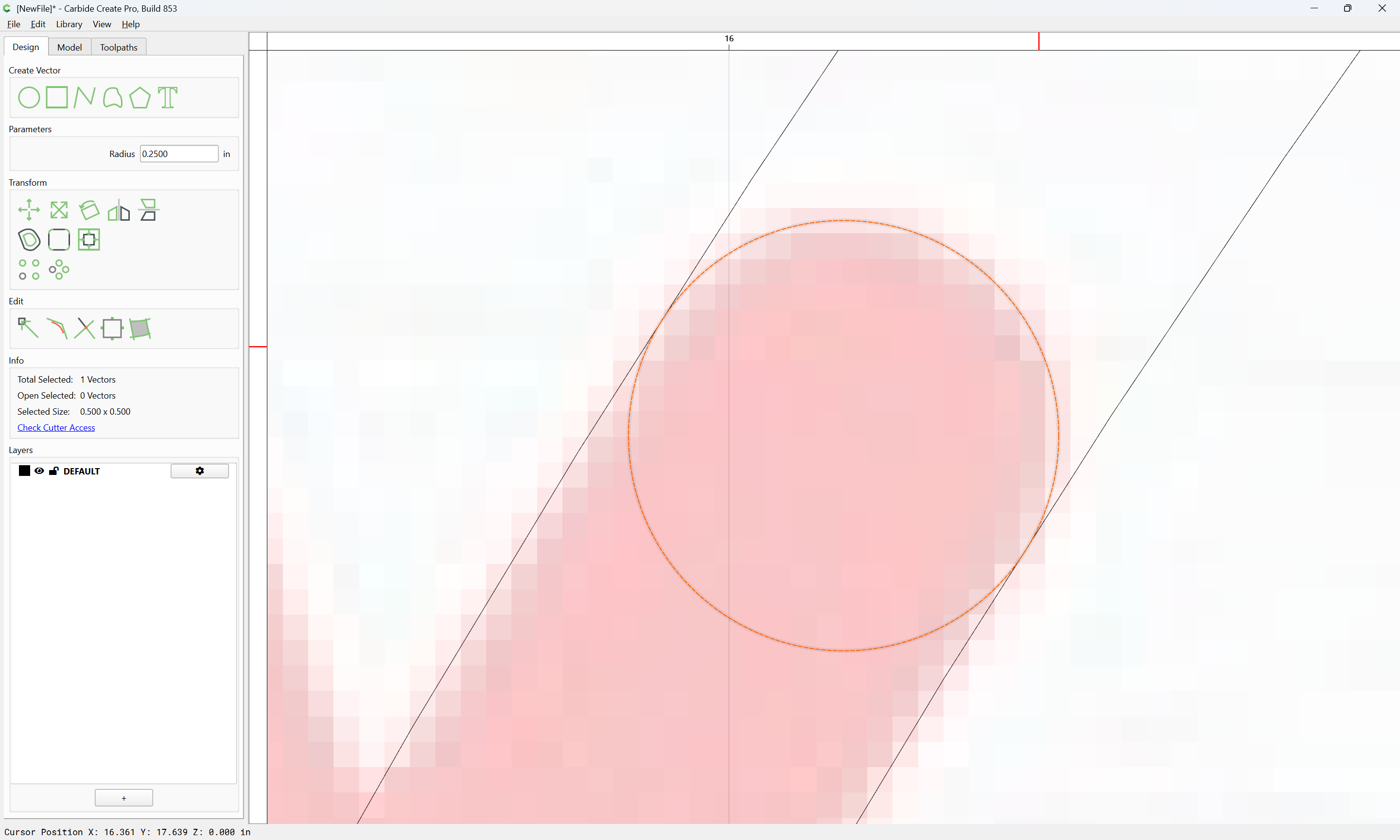
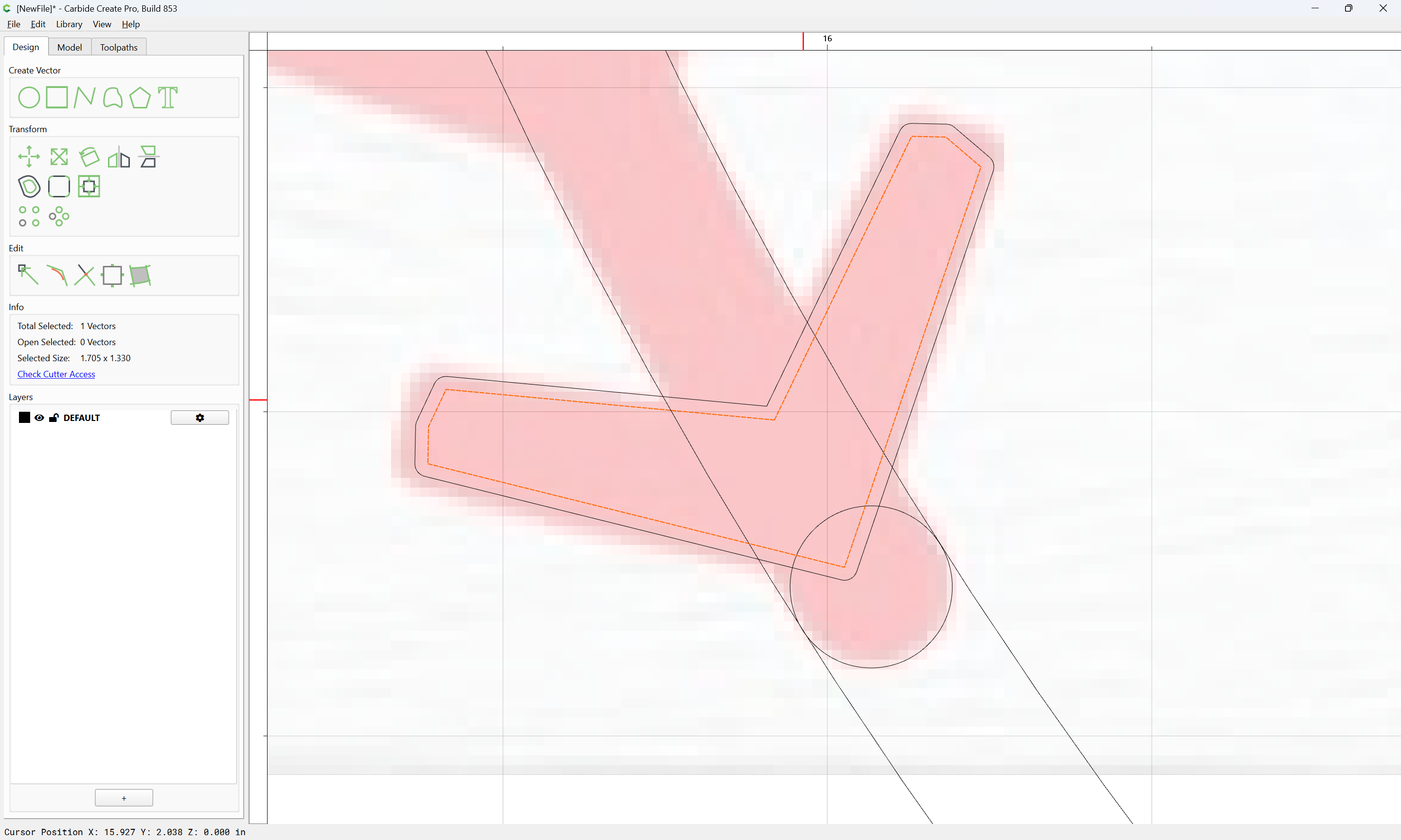
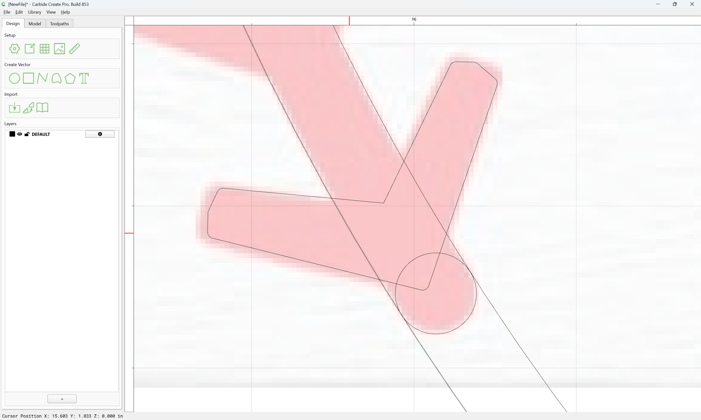
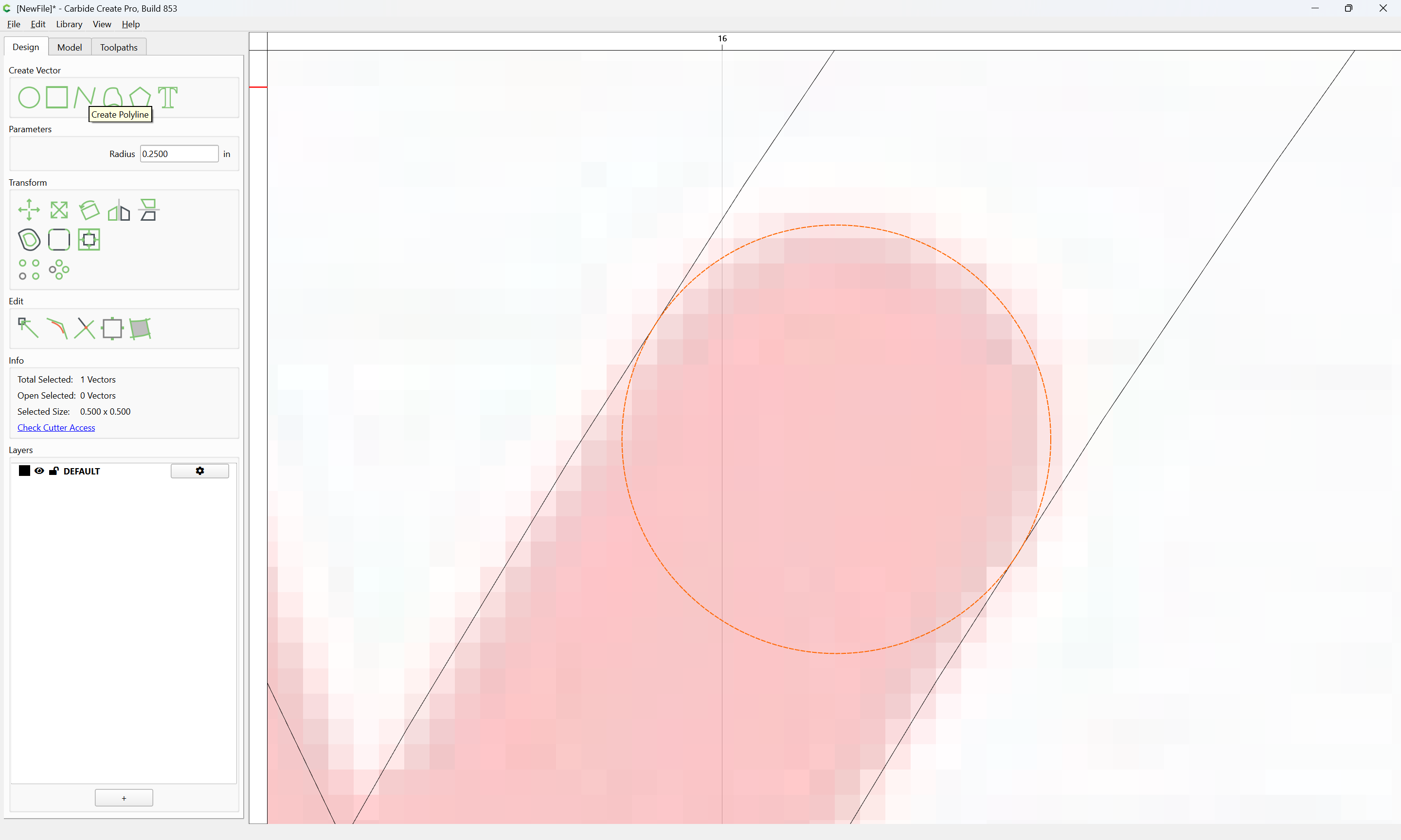
Zoom in on one end and draw a circle as a cap:
which gives us the dimension to use when we duplicate the circle:
and reduce its radius to get the other edge:
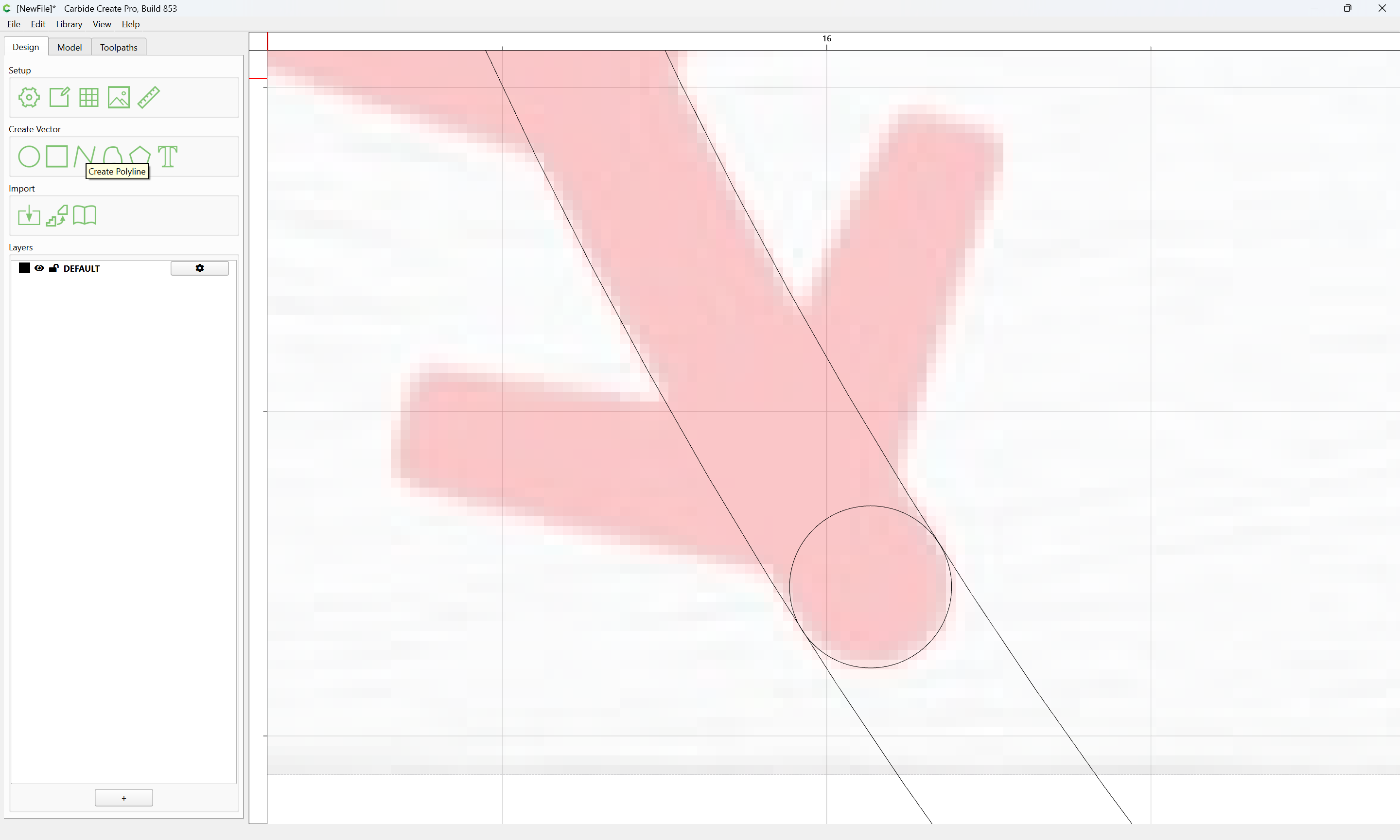
Duplicate the circle at the other end:
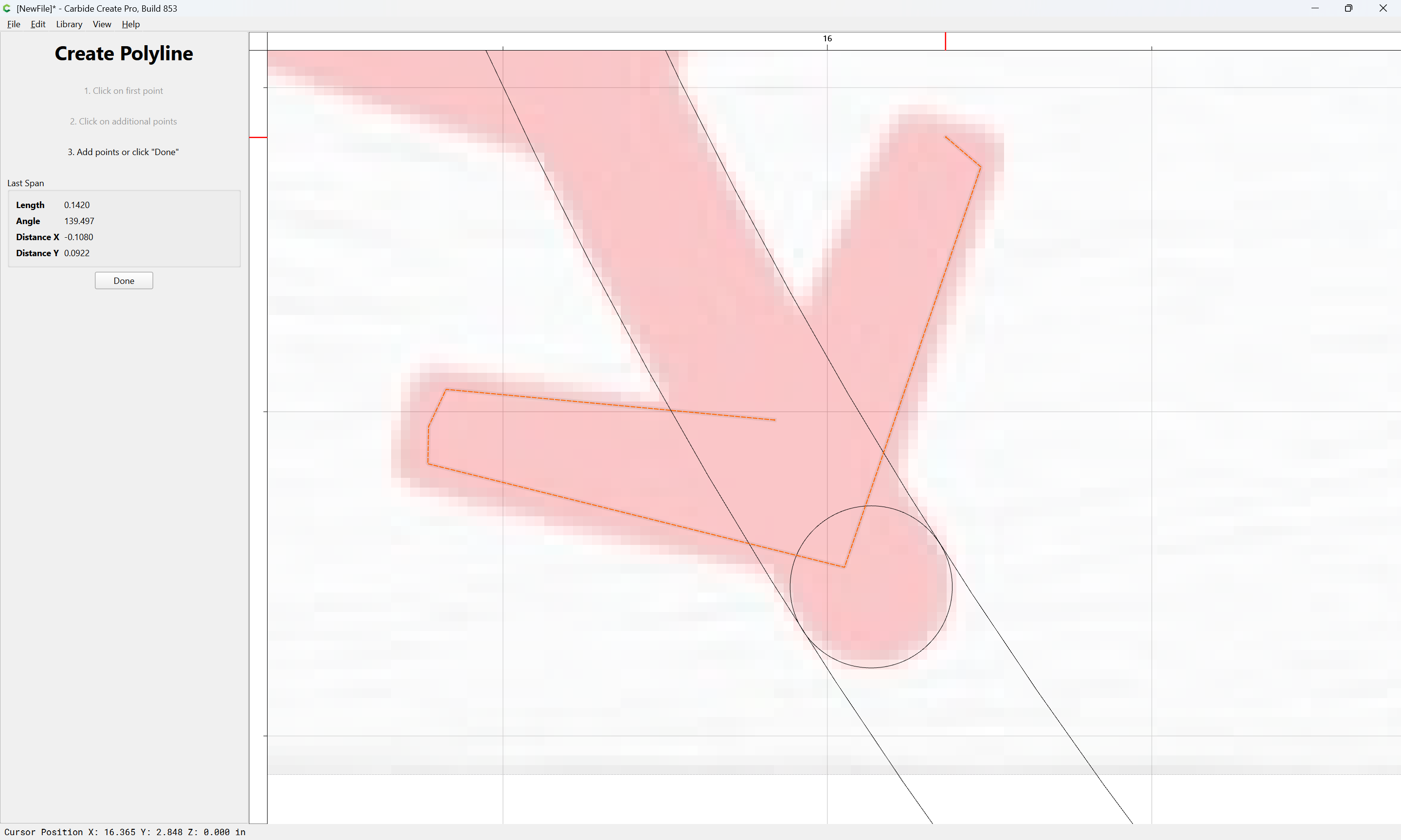
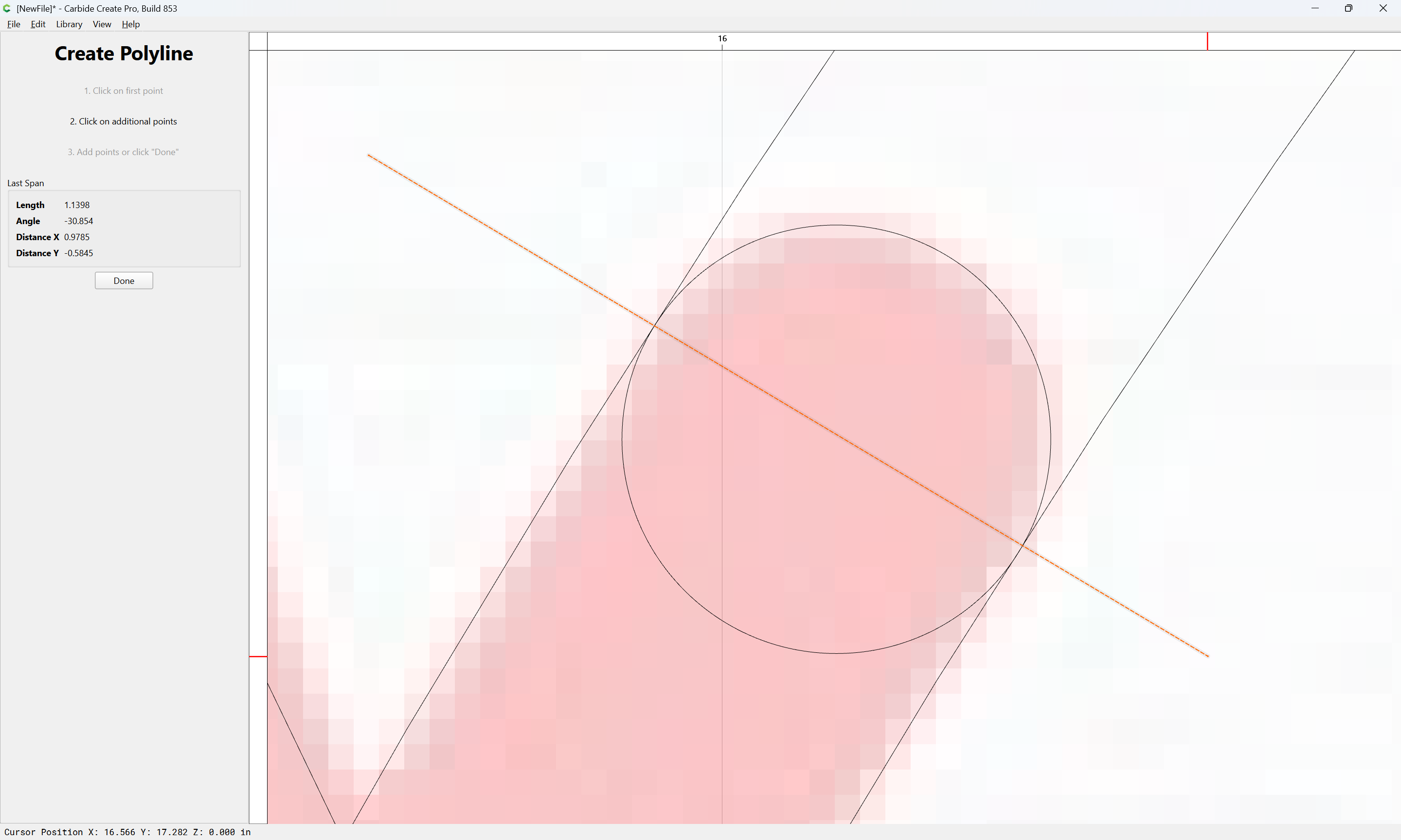
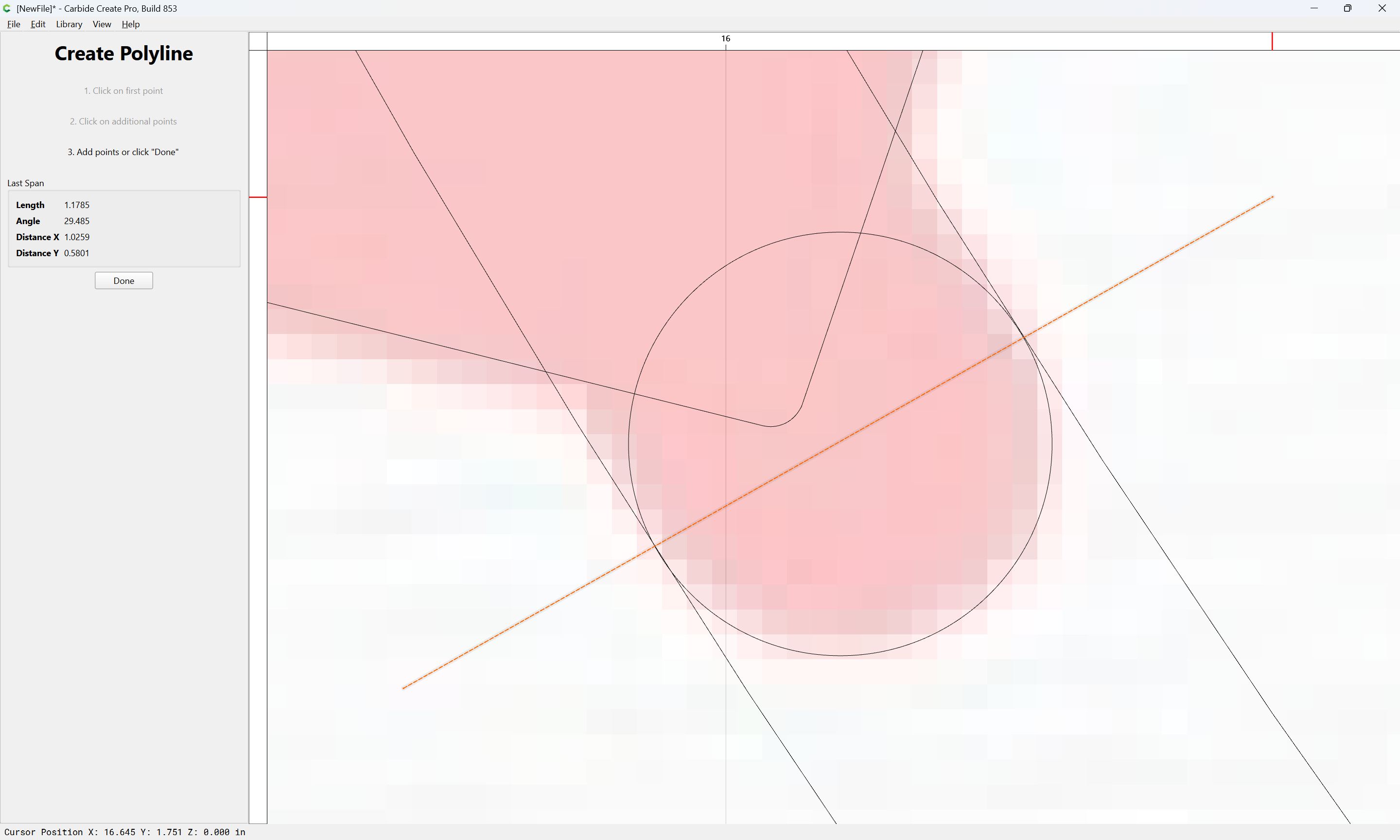
Then draw a stitch on each side:
If we draw with a slight inset to match the rounding:
Done
age|690x414](upload://j6EkBUEdxQH6SY2dO0E0mxyuNm9.png)
Select and delete the original line:
Then select one of the large circles:
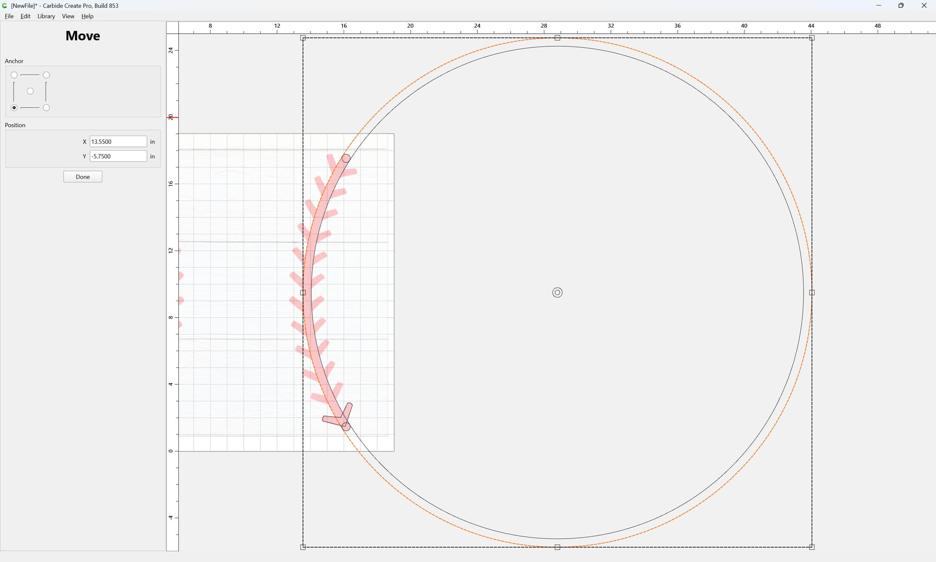
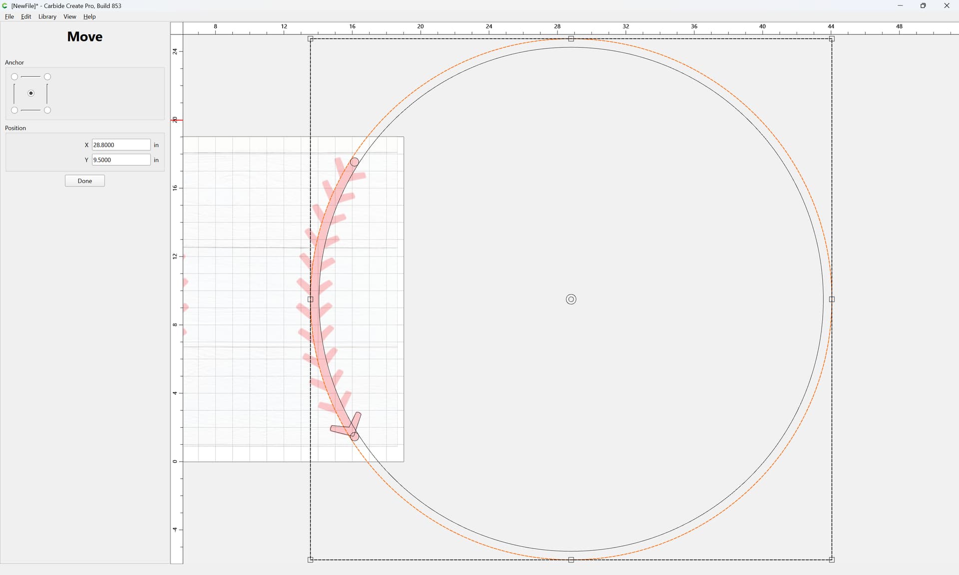
and select the Move tool:
and select the center proxy to get the center position:
X: 28.8
Y: 9.5
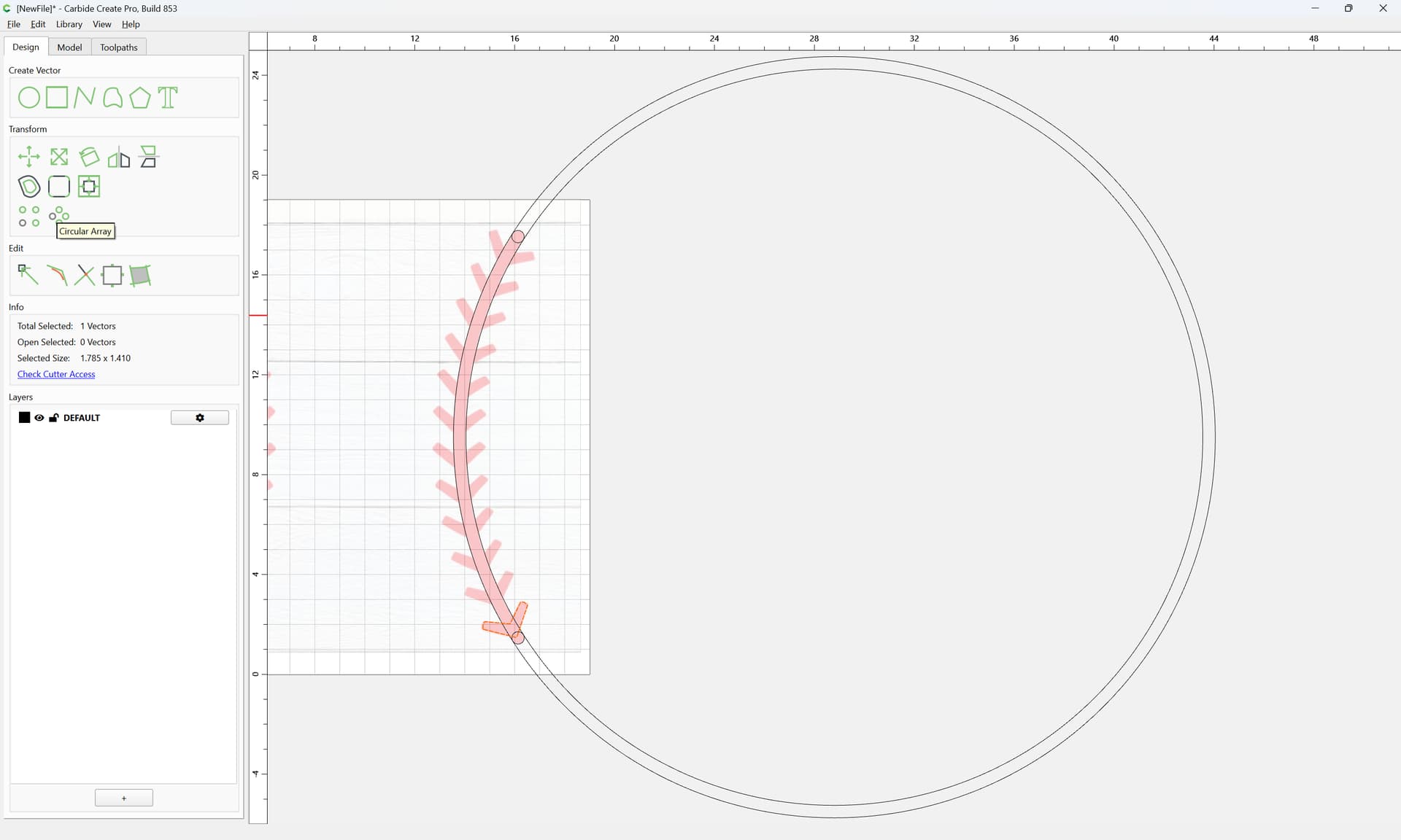
Then select the offset stitch:
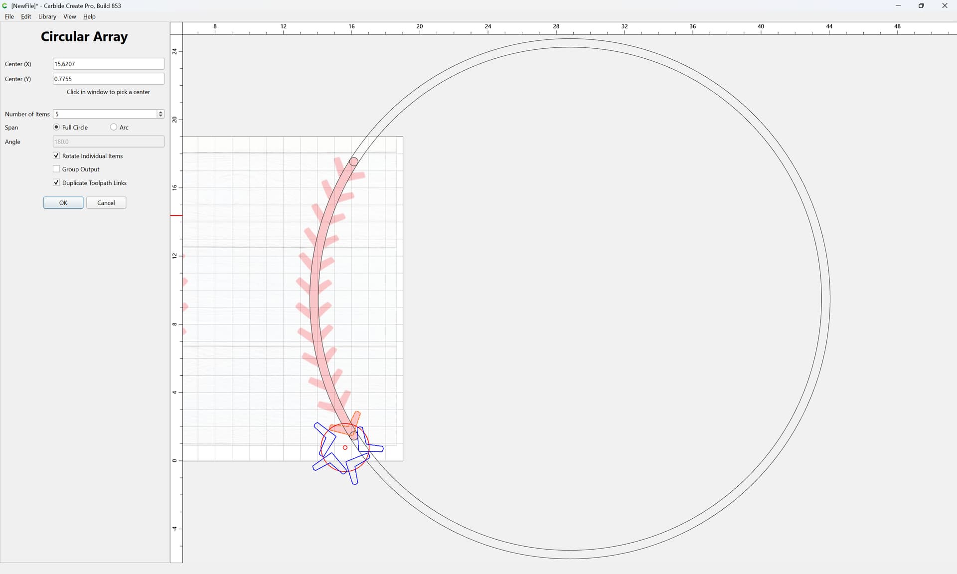
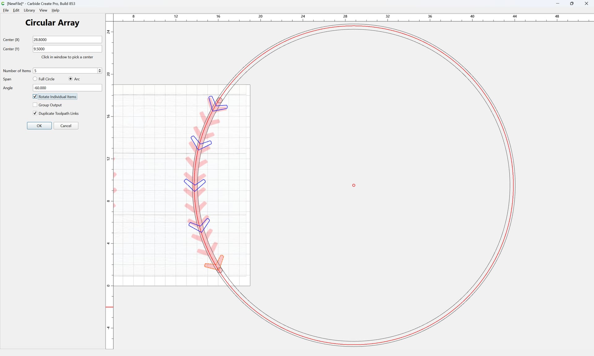
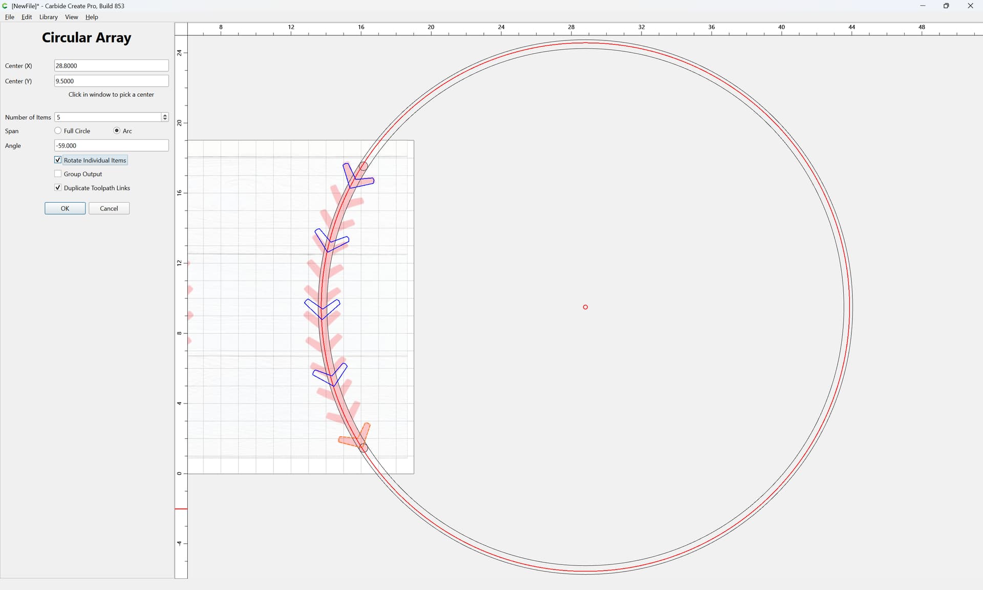
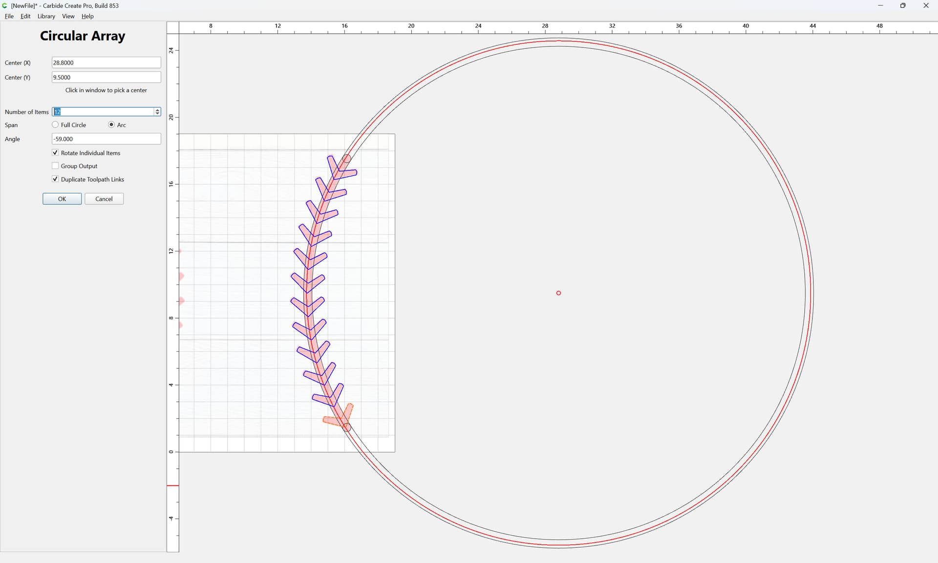
and use a Circular Array:
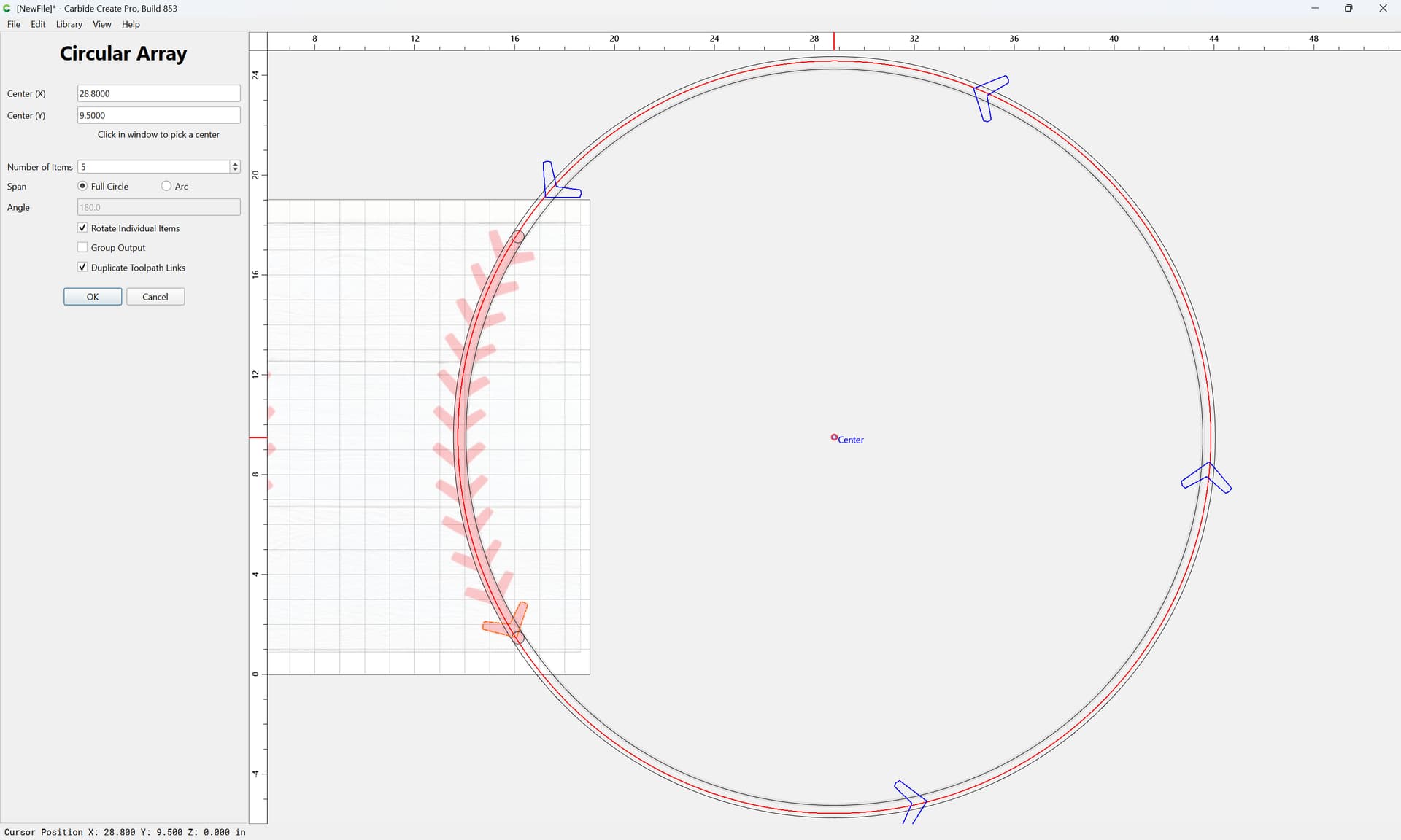
Adjusting the center position:
and the type (Arc)
and the angle:
and then the number:
OK
For each circle at each end:
Draw geometry which defines the ending:
Done
Select everything:
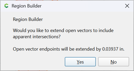
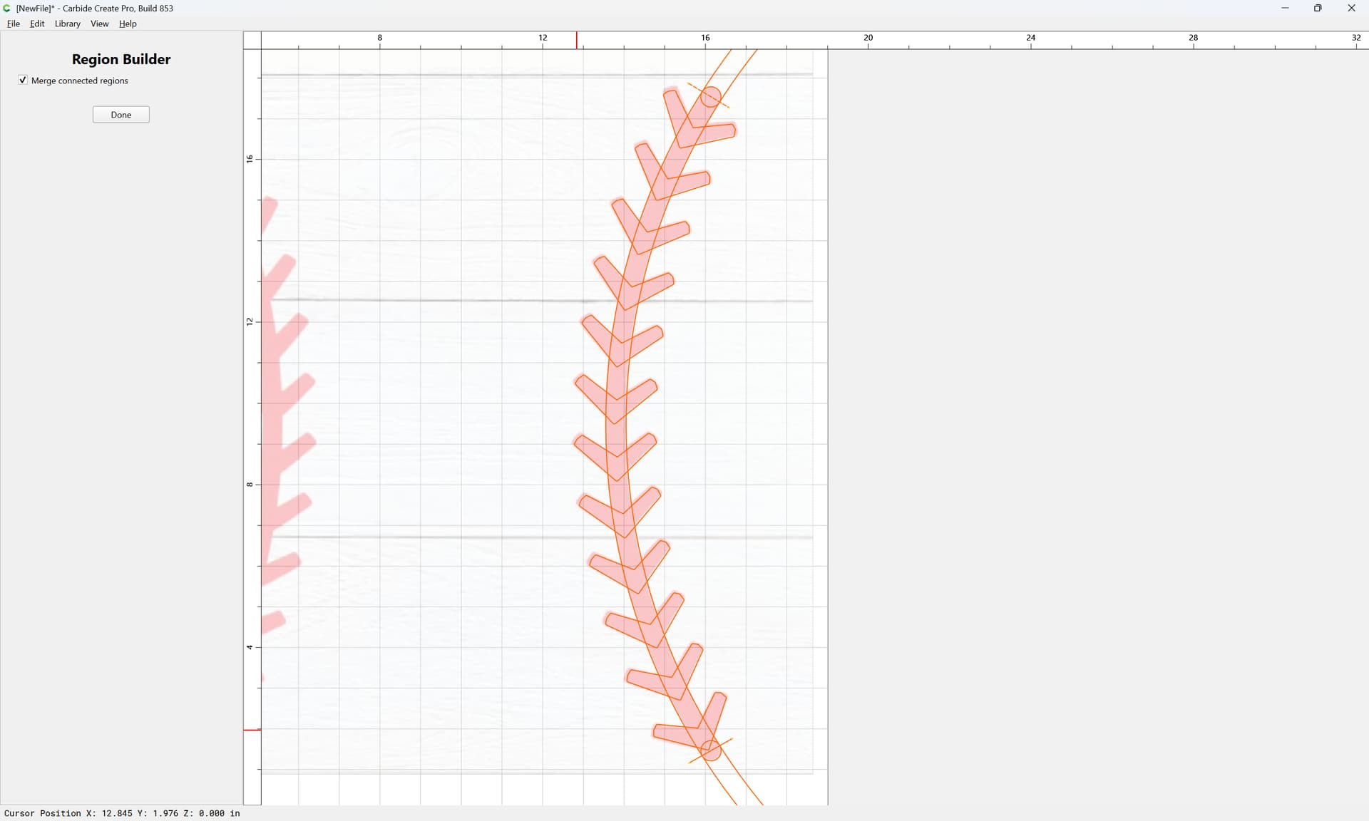
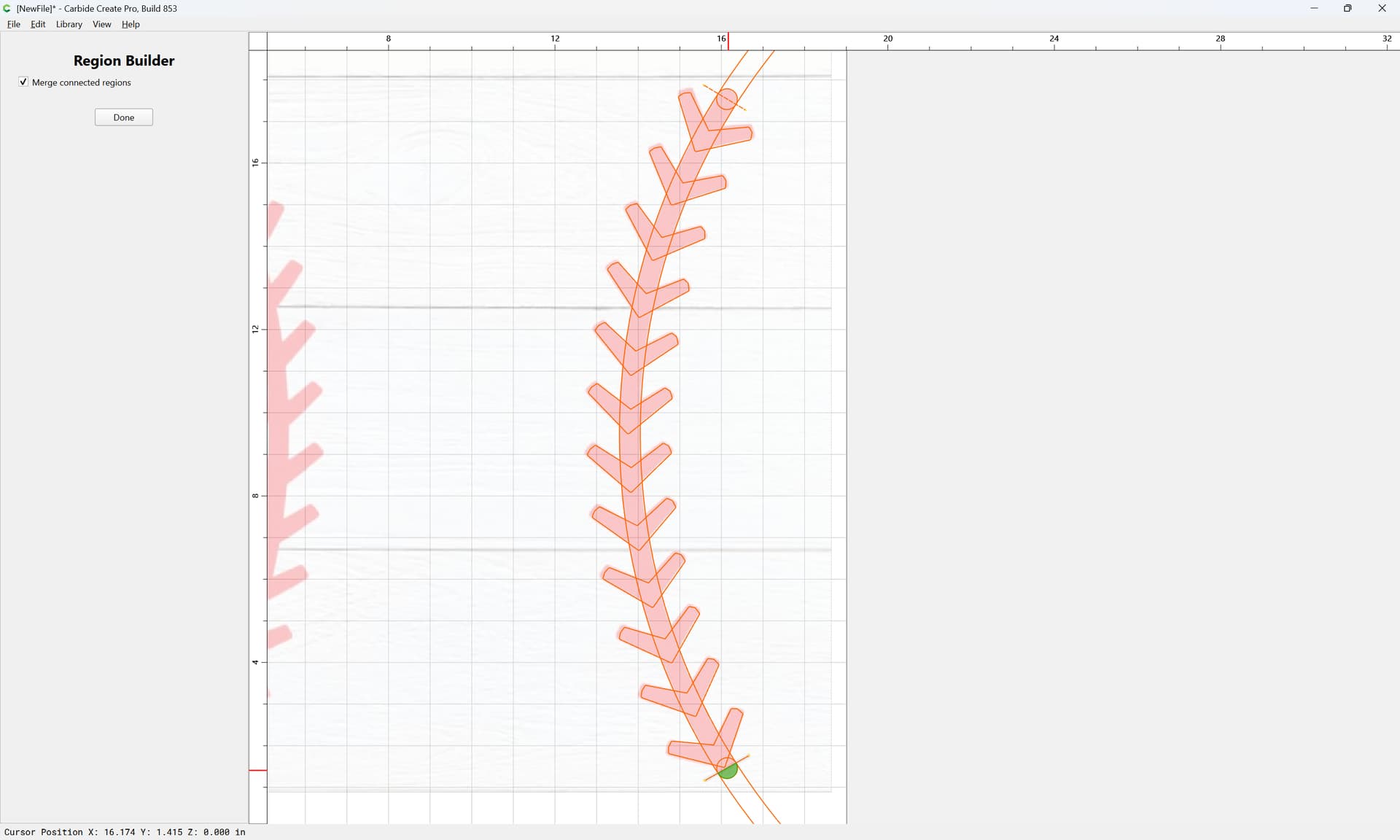
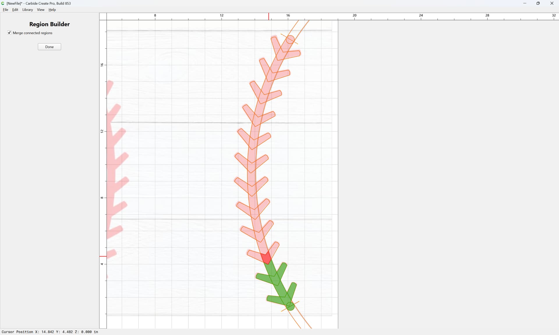
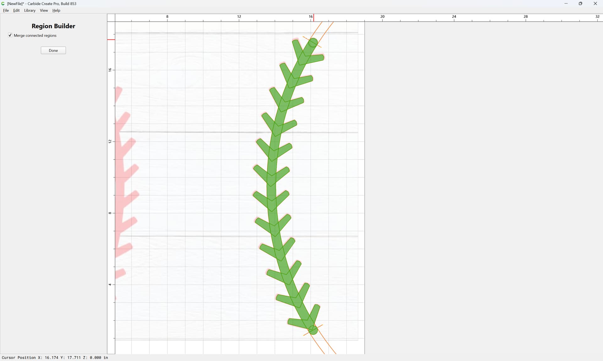
and use Region Builder to select the regions which make up the stitch:
Yes
Until one arrives at:
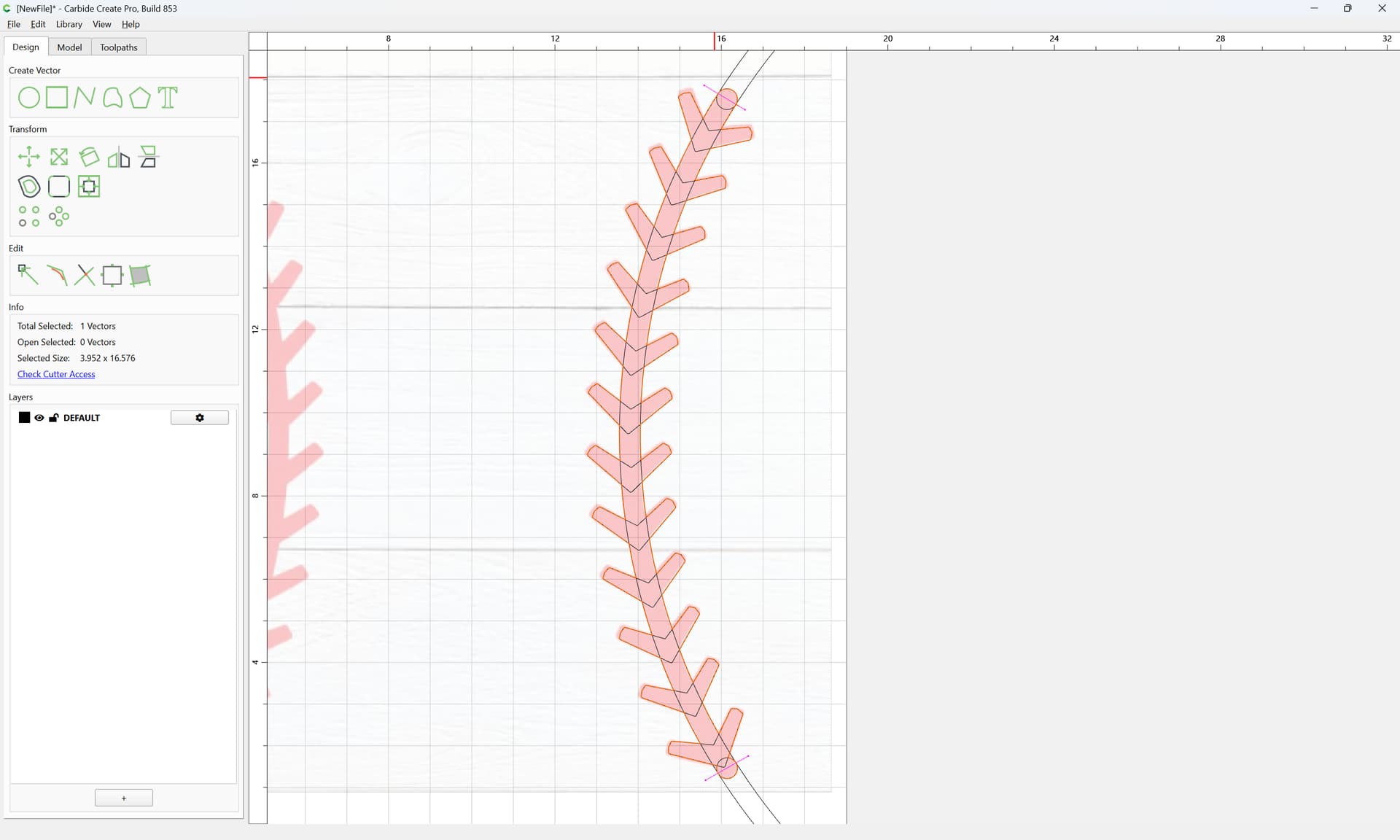
Done
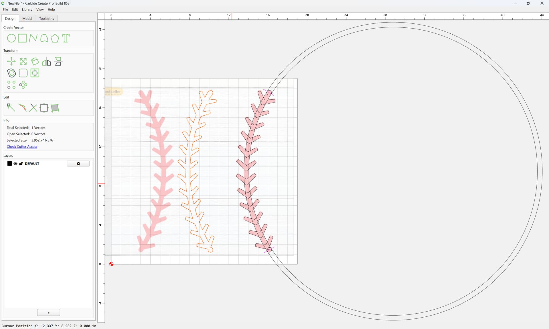
Move the resultant region geometry out of the way:
Select and delete everything else:
and then arrange:
Duplicate:
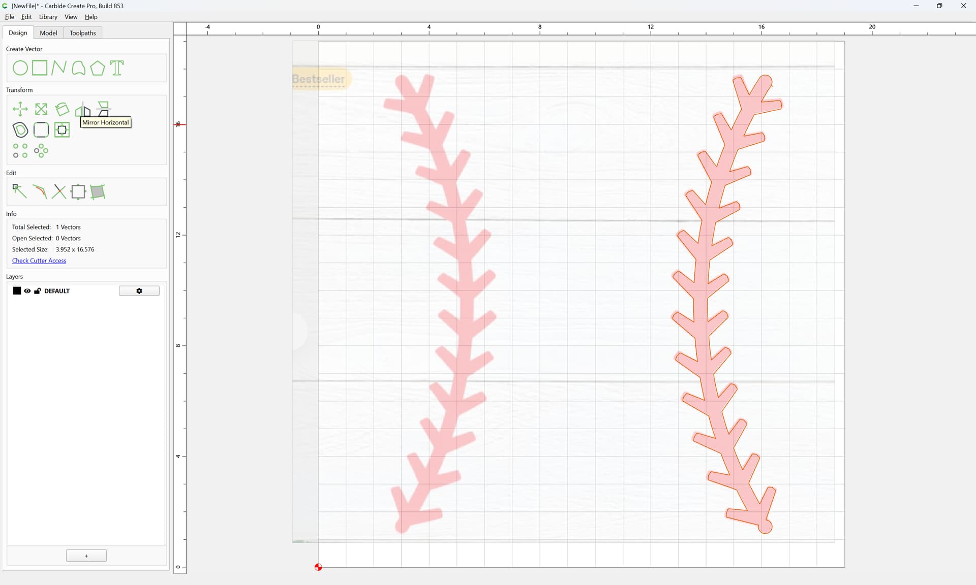
Mirror horizontally:
and move into position:
Attached as a v8 file.
baseball_stitches_v8.c2d (464 KB)
Excellent tutorial @WillAdams . I just traced the image and gave him the file like a dummy. Teach a a man to fish…
There is a baseball in the design elements library.
I used it on a home plate ring holder for the grandson.
Jim
Will, you never cease to amaze me with your knowledge and willingness to teach us.
Help again. I know it is a simple fix because I have done it already in a previous version. But after spending hours trying to figure it out again, I am asking for help because I am tired lol
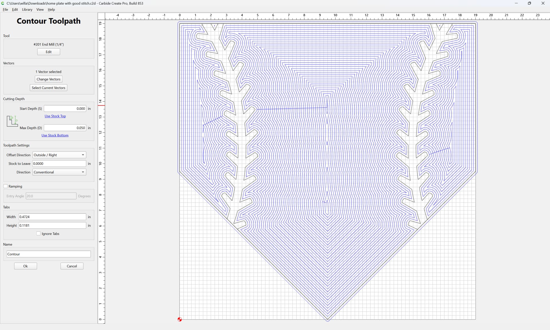
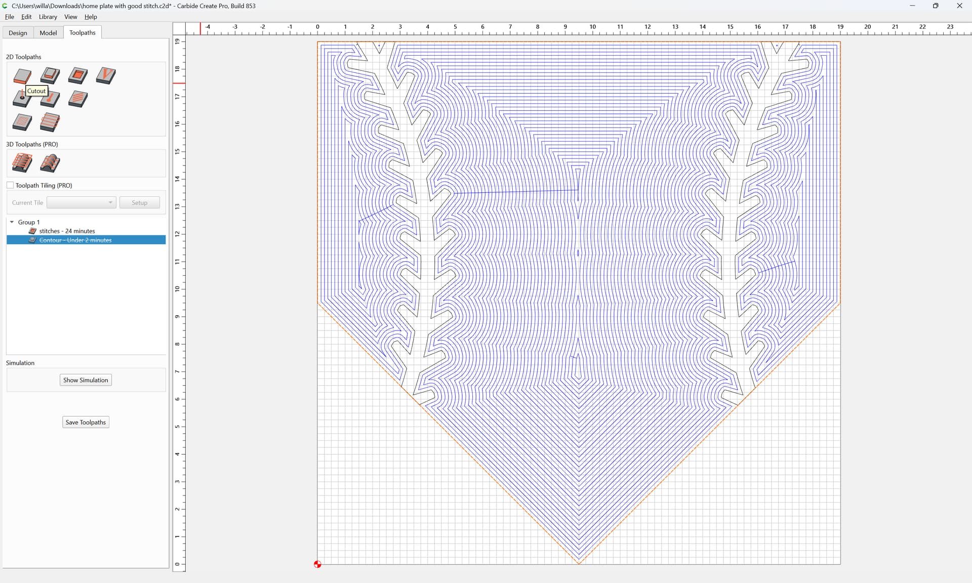
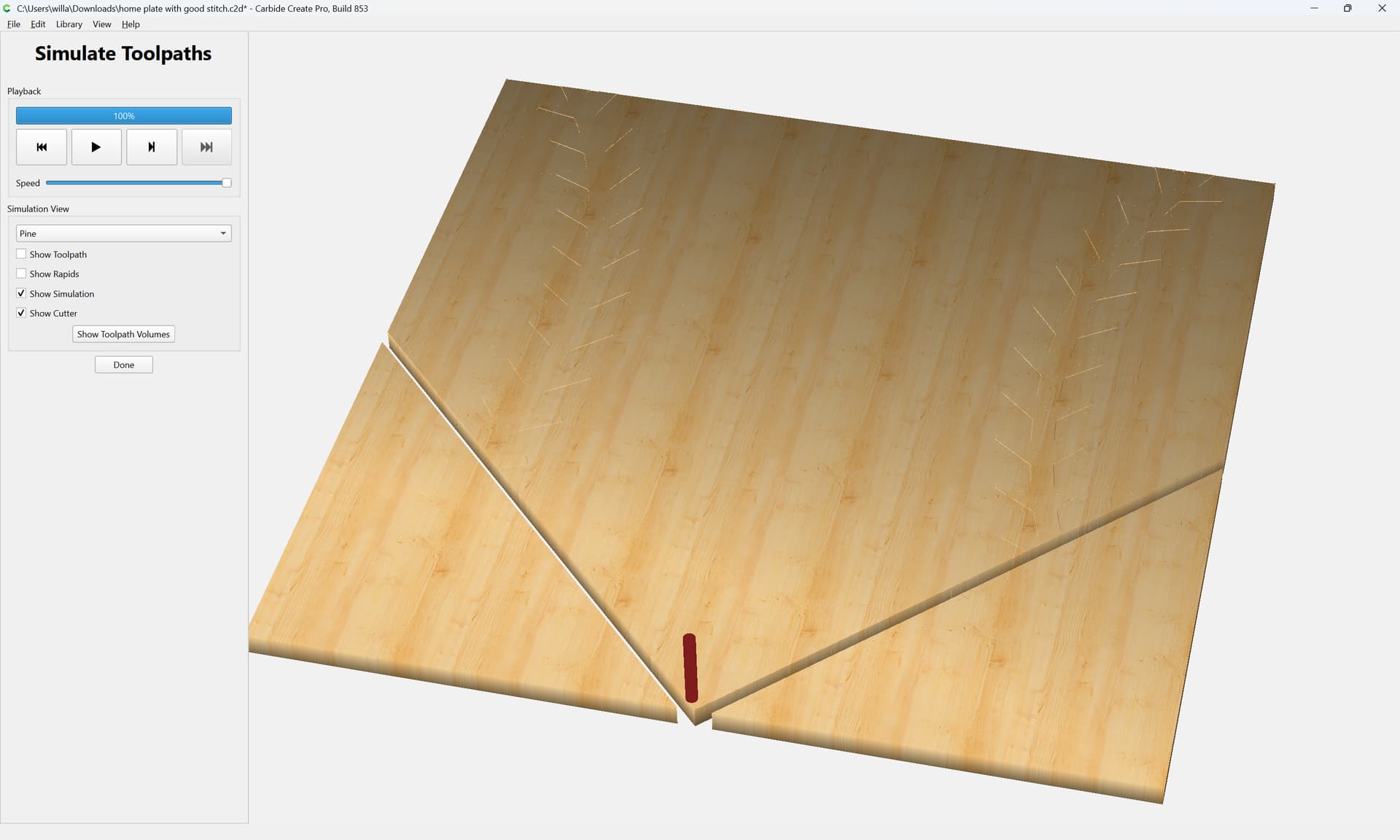
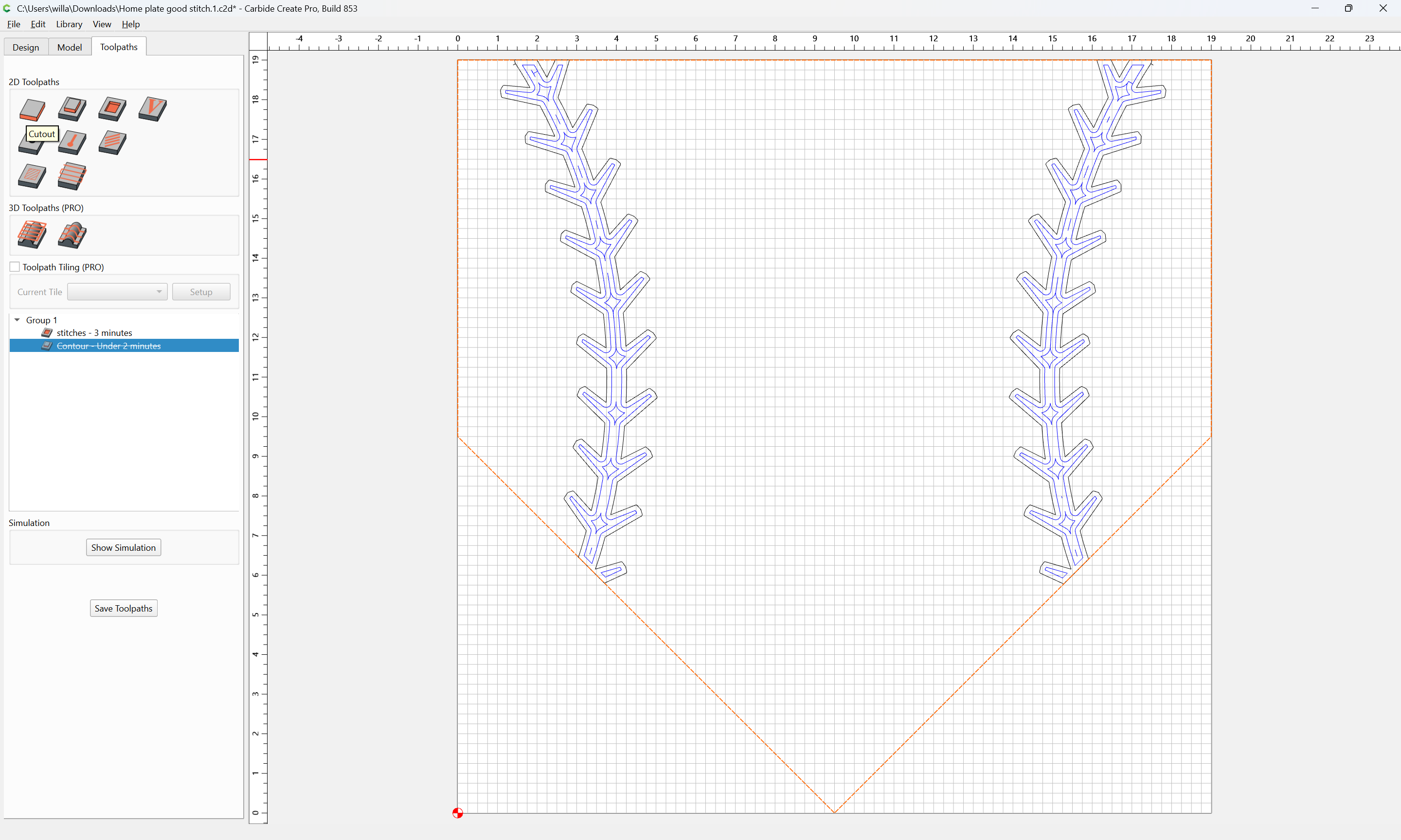
I have the stitches down to what I want and the home plate to what I want. But I need to have the home plate as an outside contour, but the program has it as pocket and I can’t figure out how to chanfe it.
home plate with good stitch.c2d (556 KB)
Try selecting the stitch vectors for the pocket.
I think that’s what you’re after.
Jim
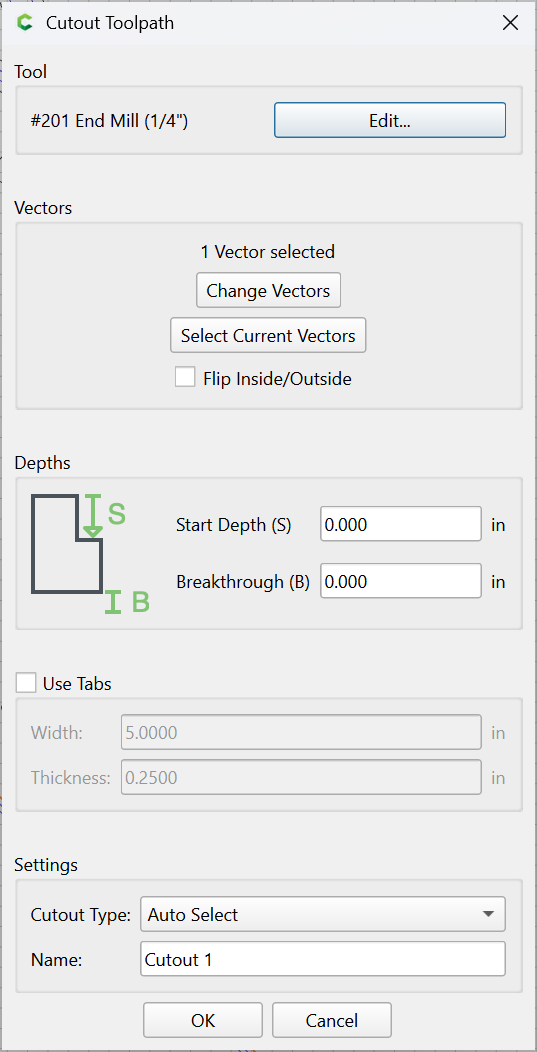
You seem to have an Outside toolpath assigned:
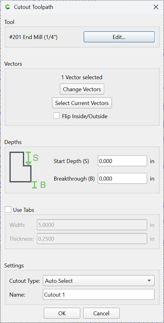
But, I believe you would actually want a Cutout toolpath:
Attached as a v8 file.
home plate with good stitch_v8.c2d (556 KB)
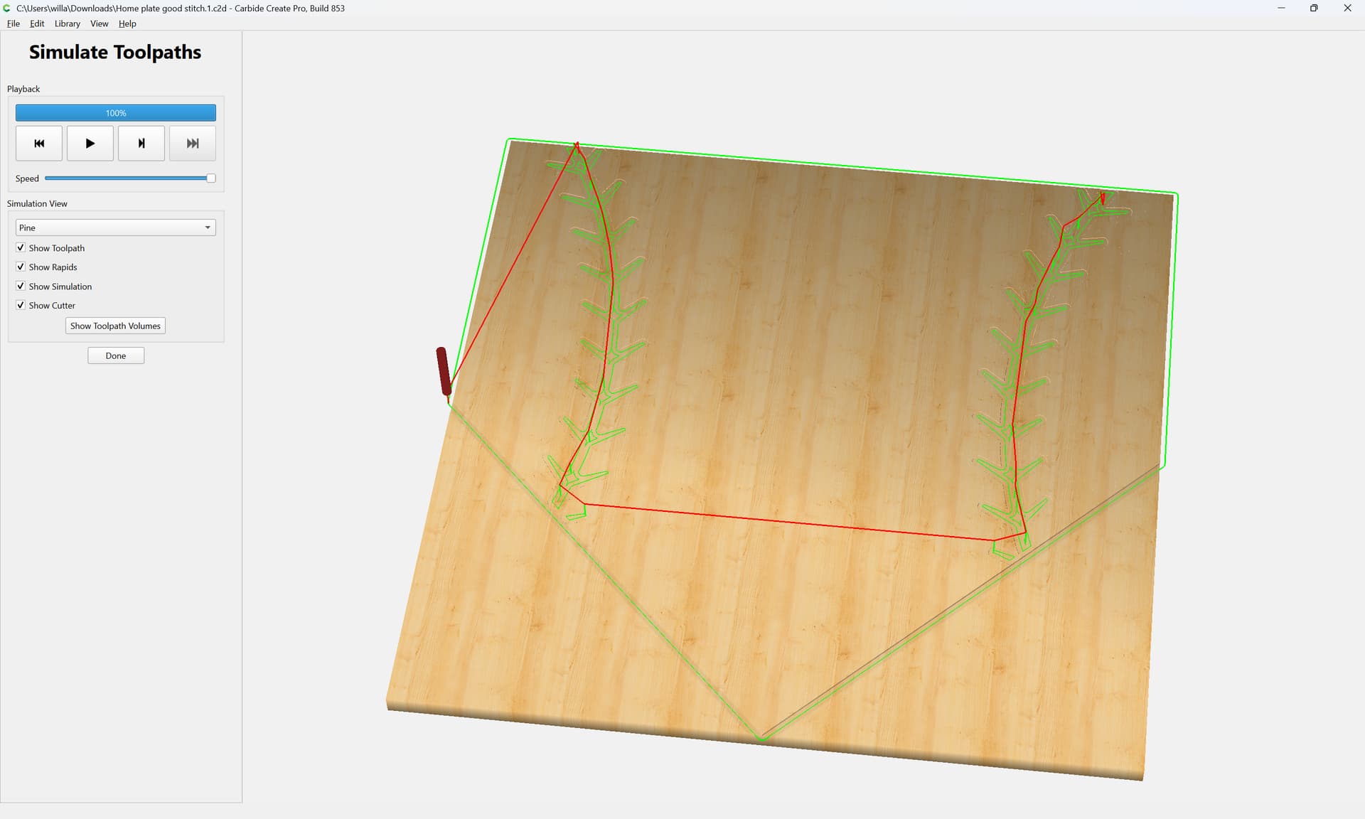
Looking at what you sent I believe it is backwards from what I need. The stitches are supposed to be pocketed and the home plate is then cutout.
The stitches are pocketed and work correctly as such. It is the cutout of the home base afterwards that is incorrect.
What’s not correct about the cutout? I looked at @WillAdams file and it seems the stitches are pocketed and the home plate is cutout. Please be more specific.
I sorry this is the file I had.
Jim
Home plate good stitch.1.c2d (480 KB)
The file I came up with.
Jim
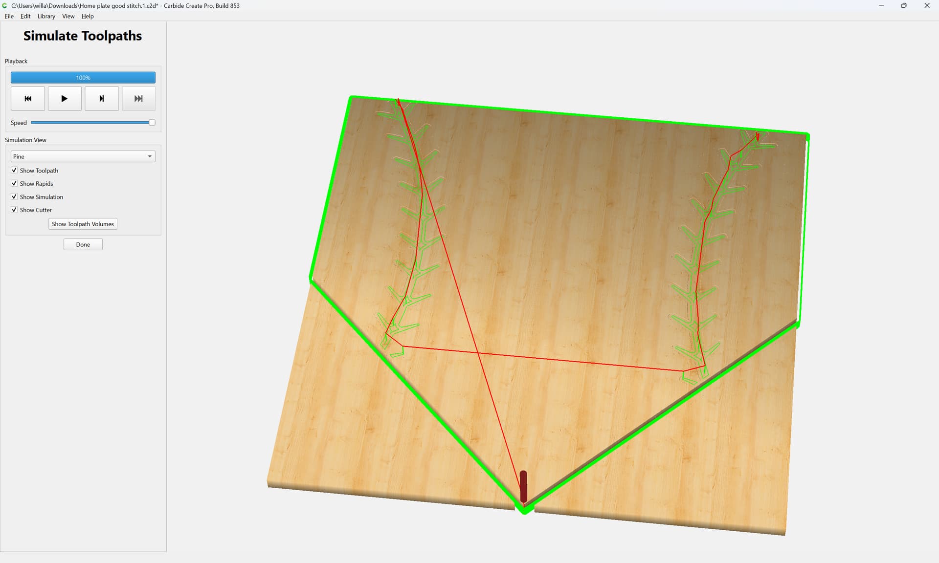
Your cutting out the home plate using a contour tool path. FYI there is a cutout tool path you can use. with that being said your depth on the cutout path is 0.05" with a stock thickness of 0.5" so no you will not cut through. Change the cut depth to the stock depth but if it were me I would use the cutout tool path function. Now that I think about it that’s kind of new so if you’re running an older software it might not be there. Also this may be a “Pro” feature but I’m not certain. change your cut depth and possibly add tabs?
Here’s a file Jim. I have more questions but I’ll explain the file. If it were me, I’m not going to waste time cutting then edges of the home plate that are square and not being cut (you have outside offset so only the front of the plate is getting cut). In this file I have a line marking the front of the plate and only that gets caught. The rest of the outside edges remain as-is meaning they are not getting cut. if you actually want to cut out the shape all around then either no offset or inside offset so then bit actually cuts the board. Make sense? I also fudged some of teh numbers so look close. .01 was made .06 for a deeper cut. Let me know if I helped or made it worse. 
For_Jim.c2d (492 KB)
I’m confused, I thought Jeff had a tool path problem.
I hope he found the answer in here somewhere.
I will try to be more detailed in my post from here on.
Jim
You’re not confused Jim, I am. Sorry about that. I was using your name instead of Jeff’s.
No worries, Shawn. More than once I have walked into a room
and had to ask myself. Self what am I doing here.
So, it’s all good.