Has anyone on here ever considered modifying their Shapeoko to a double belt system? (A quick search turned up nothing). I guess Bell-Everman owns the patent on this kind of drive, but there’s nothing to stop a person from modifying their own machines to use it. Manufacturer’s Link
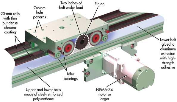
There was one user back in the SO1/2 days who glued his belts to the top of the MakerSlide, effectively creating a rack and pinion system — this is an interesting extension of that.
Interesting, pretty much takes belt stretch out of the equation. Only problem I see is getting upper/lower belts to align well. I mean it may work really well in CAD, but with our machines and all of the tolerances, it may add up to a jamb in real life. I’m sure with super tight tolerances and purpose built belts it could be done, just don’t see it with our machines. Maybe I’ll be proven wrong, whose gonna try it first?
Edit: and as Will pointed out, this is pretty much a rack/pinion setup, not sure of the advantage (maybe less backlash?), but more complicated.
Those are good points. I don’t have any real world experience to back, just what I’ve read. This guy did it with a Mostly Printed CNC machine (which I would imagine is a little looser on the tolerances than the Shapeoko) and off-the-shelf GT2 belt:
I think the advantage is that you could increase your feedrate (say, in a production type situation) without worrying about belt stretch or losing as much accuracy in the stock configuration. It also might lead to increased repeatability. Also, I think it would help if you were considering extending your rails. For example, if you had an 8 foot bed, belt systems have a clear disadvantage compared to lead screws or rack-and-pinion systems. But the cost goes up dramatically. What if you could get comparable performance to a rack-and-pinion system, but with the low cost of a belt system.
If I ever get around to doing this mod, I’ll let you know.
One thing which I think they did on the X-Carve forums was to glue belts together (back to back?) — lots of experimentation over there, and @edwardrford published a set of prototype machine designs which have some pretty interesting concepts in them.
The positional accuracy loss due to increased backlash doesn’t seem to be too much of a problem for the folks on the other side of the house that have tried it.
Generally a patent means exactly that you can not make your own. However for the purposes of this discussion you could buy a complete set of ballscrews and convert your machine easier than implementing this. Very high belt tension and it does not like dust or particles of wood in the works so to speak. We have used them on packaging machinery at high speed very effectively.
As I understand it, a patent just means you can’t sell it. If you’re building it yourself, for your own use, there’s no infringement.
And after a quick google search to check myself (you know, before I wreck myself), I have once again discovered I was wrong. It turns out, US Patent Law is quite clear on this. No exceptions for personal use.
I have experience with this kind of setup. If you go to this kind of setup you can’t tension the belts the way shapeoko was intended. Both belts are fixed at both ends, with the top belt having a “loop”. The motors are attached in some slots so that they can be moved to create the necessary tension. I have been thinking of doing this myself as i tend to think that it would greatly reduce belt stretching and increase belt life.
However as someone i think mentioned earlier, ball screw is probably the way to go. Also there would be concern for there being enough clearance for the second belt. The v-groove rollers and the bearing rollers are really close together so there is the worry that the bearing rollers could start riding “on” the belt and cause some serious binding.
Initially i had wondered why shapeoko hadn’t done this in the first place as it would be a huge advantage over the current setup. However it also make the adjusting of the belt tensions more complex and would definitely cause people more grief.
But yeah. The bottom belt would be glued down as it will never move. The top belt would simply lay on top, meshed, and clamped down to keep it from shifting in either direction.
In the DIY setups I’ve seen, they’ve added an extra roller in between the motor pulley and one of the bearing rollers. The extra roller is on an eccentric nut so that you can adjust the tension that way. Having looked a lot more closely at my S3 since I posted this, I think you’re correct that there isn’t enough clearance between the roller bearings and the rail for two belts. But, if you were brave enough to modify your end plates ever so slightly, it could be done.
Absolutely. It’s been on my mind to do that ever since i assembled it. It would be well worth it I’m sure. I just havent had mine long enough to possibly be bothered with the belts stretching. I’m having too much fun trying to learn it still.
I’ll have to take a look at the DIY setups. It doesn’t look to me like there is enough room for a belt tensioner pulley.