Since it seems to have been decided that you cannot manually turn on the VFD and then move it via Carbide Motion, is there a recommended way to trim a fence using the VFD to ensure it is perfectly parallel to either the X or Y axis of the 5 Pro? I would like to just do something simple like Carbide3D shows in their own video here - https://youtu.be/ViVkQIEvRiw?si=e7Ih-o2u44hfm57E - with the hardwood fence in the left (black) T-slot. With the other spindles, it would be easy to just manually trim the fence to be perfect as shown around 1:20 in the video. With the VFD, the cut seemingly must be made via a program. However, you also can’t seem to just cut a straight line with the Carbide Create and Carbide Pro combination. You have to cut a rectangle. Is the suggestion just to program in a very narrow rectangle and hopefully miss all the metal surrounding where the cut is to be made? Seems like a 2 minute, simple task with a regular spindle turned into something more difficult and risky.
You could do a single line with a contour tool path.
Thanks, I’m seeing that now. Since I’m trying to cut something at the left-most reach of the spindle, how would people suggest doing that? My first thought is essentially to create a new design with a stock size a little larger than the wasteboard kind of like when surfacing and the origin in the bottom left. Then, draw a single line on the left edge from the origin straight up to the top-left edge. Next, set up a Contour cut for that line with the offset set to outside/right (not sure about this one). Then, set the origin of the 5 Pro to the front-left corner as far left as possible without the bit being over the black t-track in the frame. Finally, cut and watch closely to make sure the wasteboard or frame metal isn’t damaged. Thoughts?
Edit: Maybe the width of the stock size doesn’t matter as long as the line in the design goes from the bottom-left origin straight up, and the origin is set correctly on the 5 Pro itself to align the bit as left as possible to make the cut.
I wouldn’t push it to the extreme left unless you really need the space. You might want the capability to recut your fence later in case you mess it up at some point.
One thing that I wish I did on mine was find a way to make it more easily removeable/replaceable and get it back aligned properly.
On Gen2 I am thinking about cutting the bottom side such that a portion of the fence itself drops down into the TTrack slot. Just having the bolts in there still allows for a slight left/right wiggle.
I guess an alternative could be spacers on the left side that would always keep it aligned without having to recut.
I have the 4 Pro XXL, so space is at an even higher premium than on your 5.
I like the idea of using spacers to the left to install then flush trimming the right with the spindle. Removing and re-installing would be easy with the spacers for precision. Good thought! ![]()
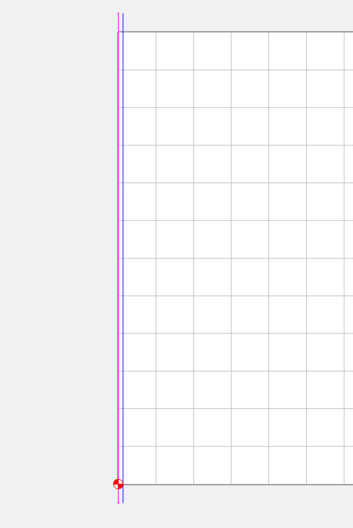
If you make a generic program to cut your fence you can reuse it. If your fence sections are about 12" like Kevin’s, make a 13" line that overlaps 1/2" on either end, from 0,-0.5 to 0,12.5. Create a contour toolpath on that (open) curve. You may need to switch left/right as it doesn’t know inside/outside on an open curve.
Now you can set your zero point to the front right corner of your fence, bump it over to the lift just a smidge, and run the program. If you have 2 like he did, move your cutter to the front of the second fence, don’t change the X zero, but change the Y zero.
If you ever need to reface them, use the same program setting your X zero another smidge to the left & take a few thousandths off.
Cheat:
You can do the small, medium, and long single jogs and the spindle stays on. Also, if you do the fast jog and let the soft limits stop it, the spindle stays on.
I use the contour toolpath on the line with a pattern that allows me to surface some of my pieces to be machined. The path is just a back and forth move that steps over half the distance of the cutter. This idea escaped me until Will pointed it out to me and then it was like a light bulb popped on in my head.
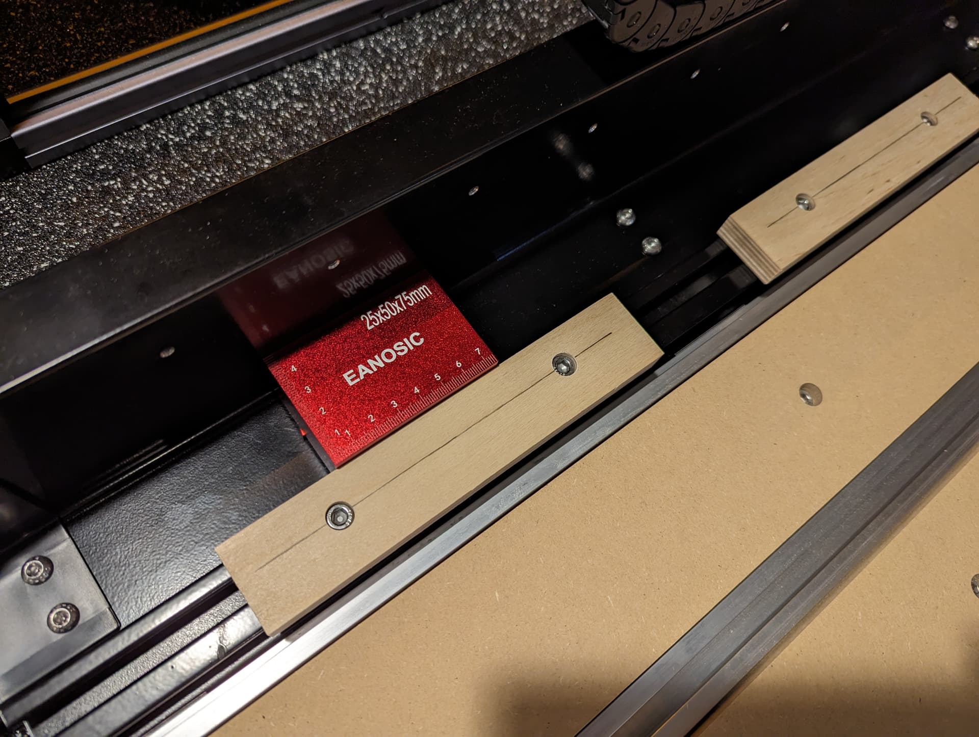
Good call on the spacer idea. There is definitely some play with the tee nuts as you mentioned. One note for anybody else looking to do something similar with their 5 Pro - the corner where the frame goes from horizontal to vertical (where the red spacer block is sitting) is rounded. So you need to elevate your spacer by about 6mm or 1/4" to get it to sit square against the vertical part to achieve proper accuracy.
This topic was automatically closed 30 days after the last reply. New replies are no longer allowed.