Bird house with cedar tiles

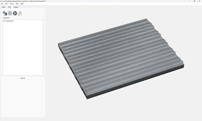
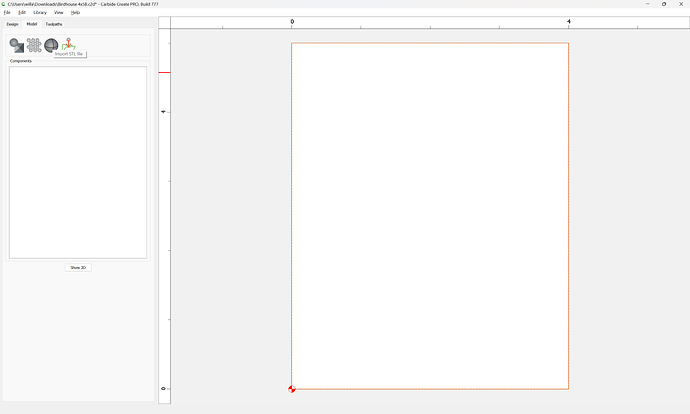
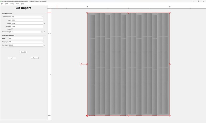
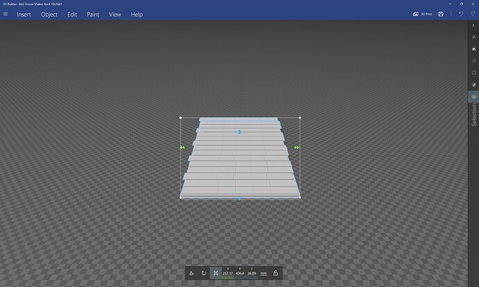
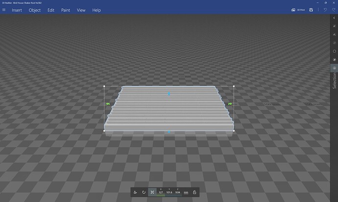
Given an STL file:

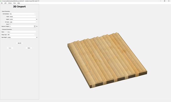
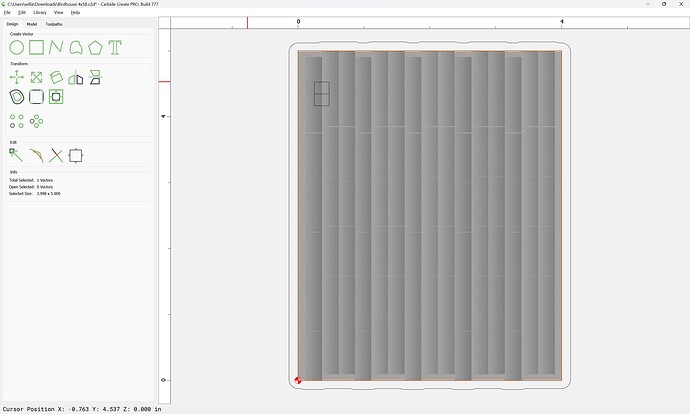
which is to be used to effect greater verisimilitude in a birdhouse:

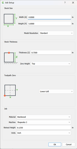
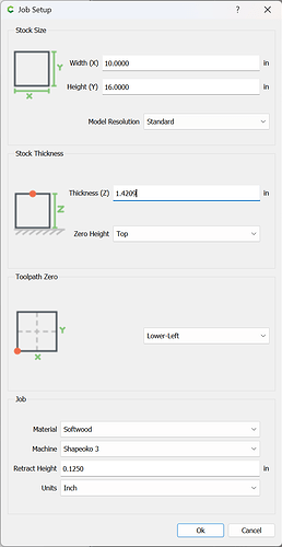
the first question is why use 3/4" thick stock:

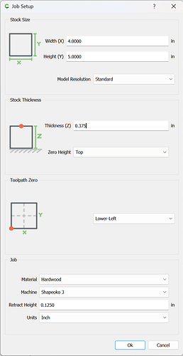
reducing that to match the thickness of the model (3/8")

has us cutting away much less material.

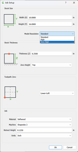
A further consideration is that the Model Resolution was set to “Standard” — increasing that to “Very High” and re-creating the design:

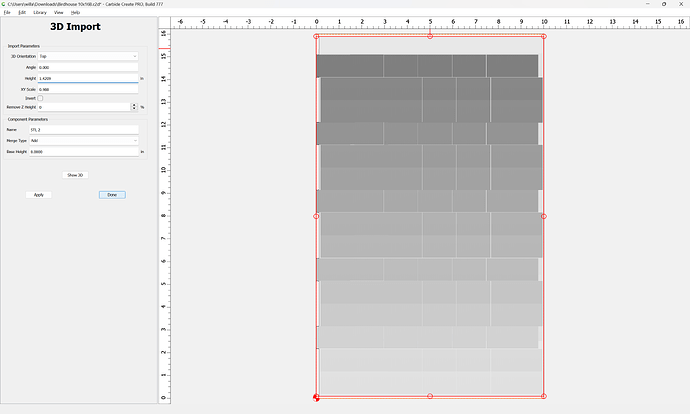
and a further consideration is proportion — presumably we want the model to be imported at actual size, so we rotate it (or the Stock dimensions could be flipped):

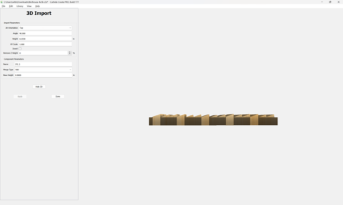
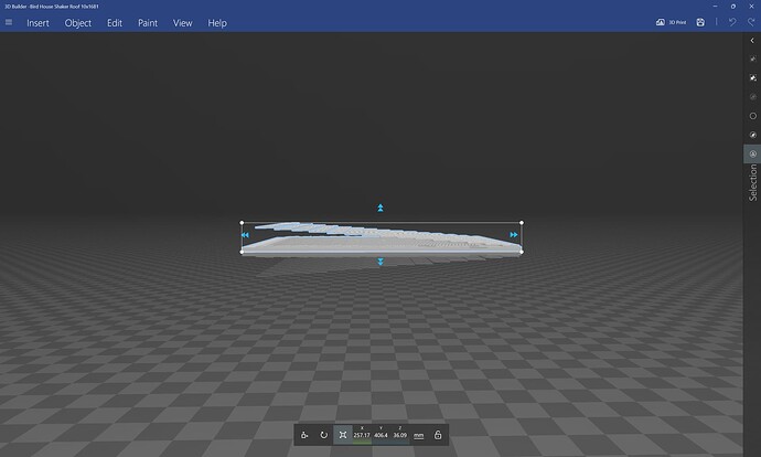
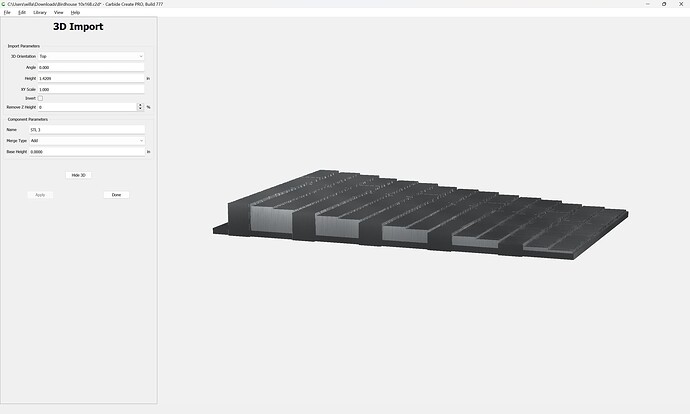
One concern here is that the model has vertical faces:

and it will be necessary to use tooling which will not interfere.

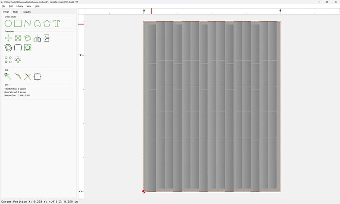
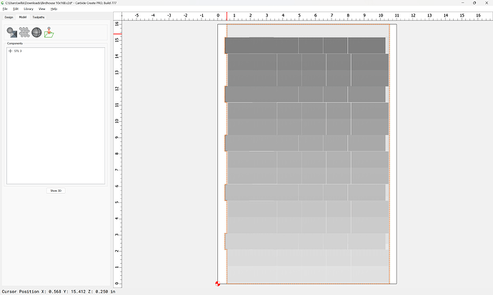
To actually cut out the part, it would be best to select the auto-traced geometry:

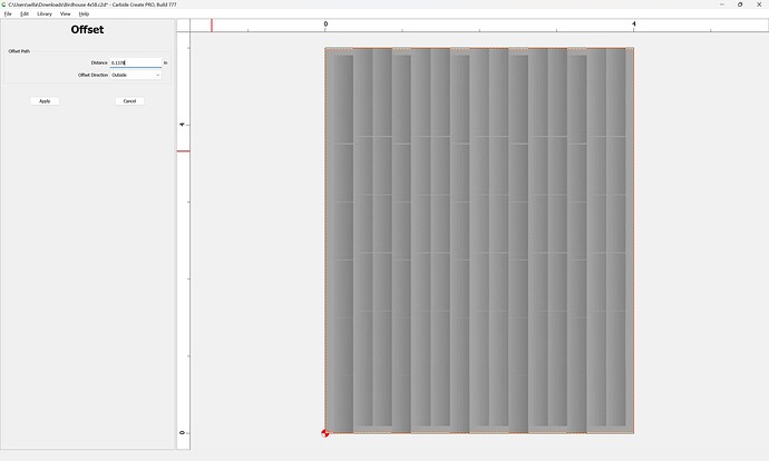
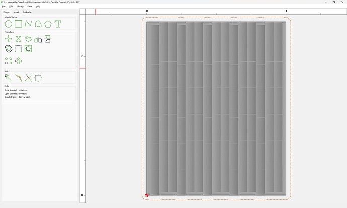
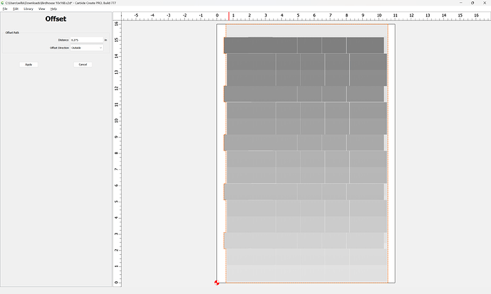
and offset to the outside by tool diameter plus 10%:

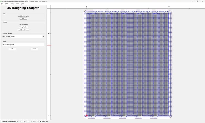
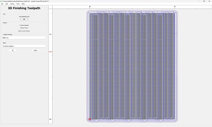
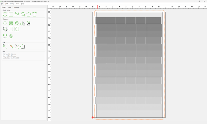
Edit the toolpath to change the associated vector and select a suitable tool for roughing:

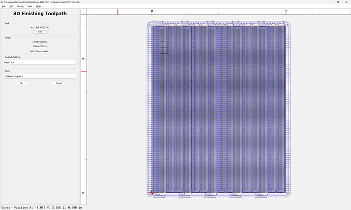
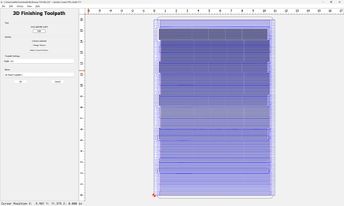
and finishing:

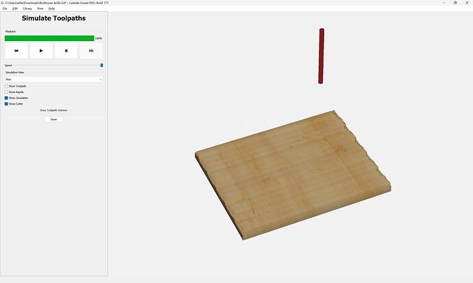
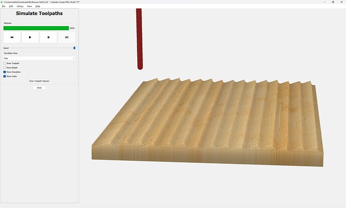
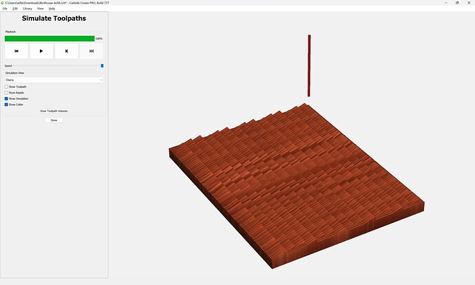
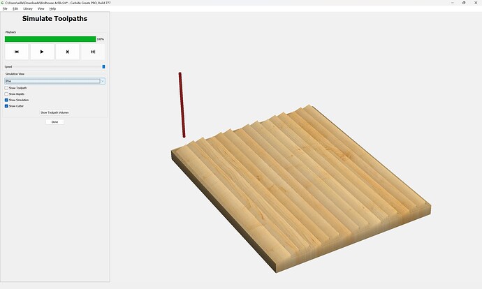
which gets us a bit closer:

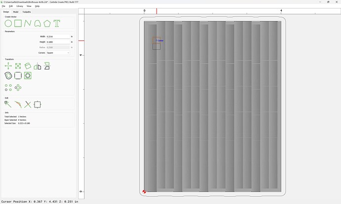
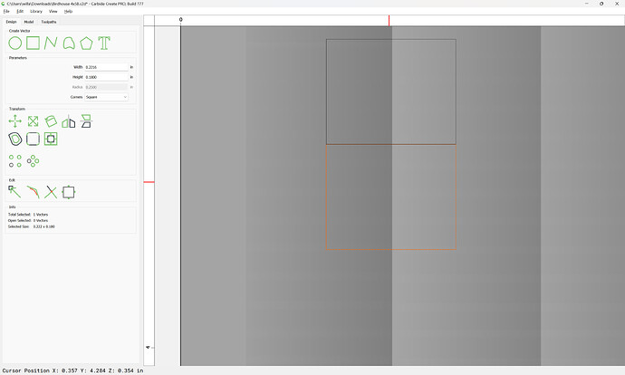
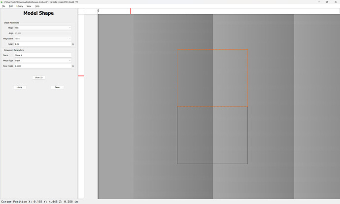
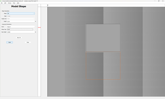
For a final result we will need to determine the height of the edge of the “shingles” — this is most easily done by drawing in a pair of rectangles:

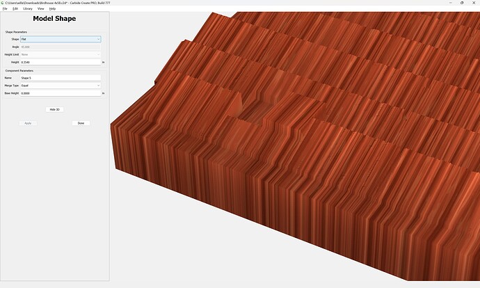
and then model each to a thickness to determine/verify this height:

and the height difference is ~1/8"

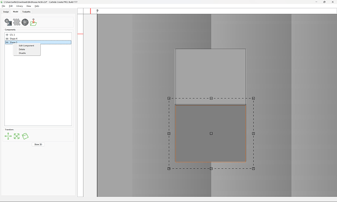
So, any tooling used must have that length of shaft/cutting flute equal to the diameter, which means that for Carbide 3D tooling we cannot go down to a #121 which only has a Cutting Length of 0.0625" — the #111 with its cutting length of 0.25" will work — after deleting the measuring models:

Since the #111 is just one size smaller than the #102 used for roughing we merely need to change to the traced surrounding geometry:

which gives us a quite good result at the default stepover:

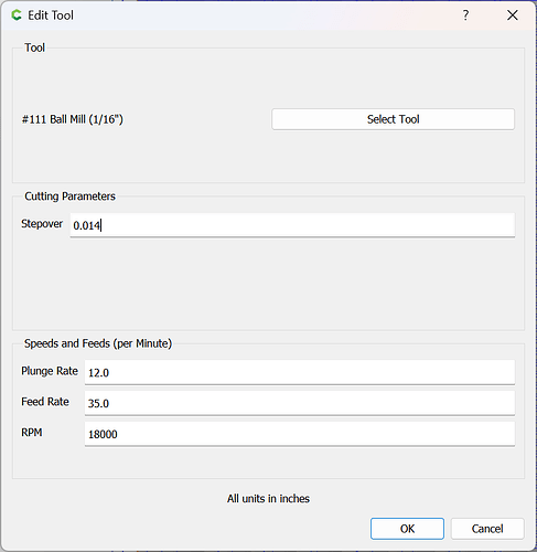
If desired, that can be increased:
3 Likes

Great tutorial, William. Thank you.
I went right away and re did my work, including cleaning up the stl file on tinkercad.

The smaller test file, 4 x 5 inchez we are practicing on turned out good.

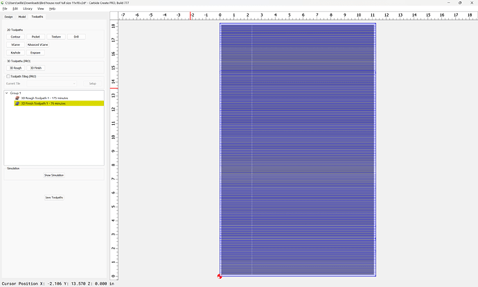
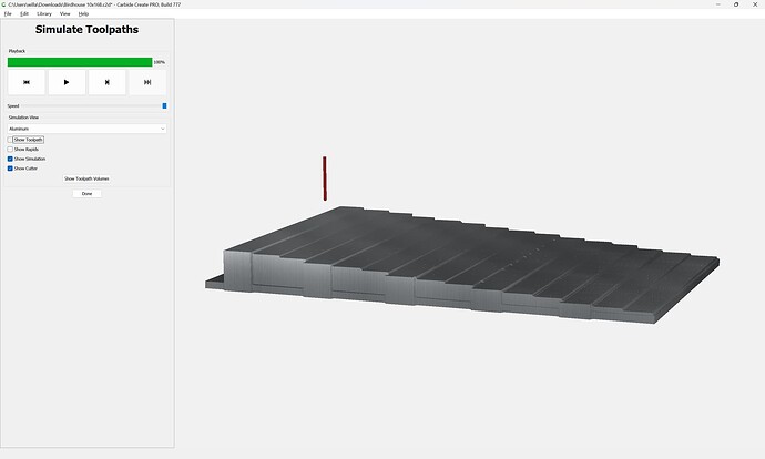
Now, I tried setting up the full size version, 11 x 18 inches. Right at the simulation, I can see the tool path going just around the piece and not doing the rough cut w the .25 end mill. And it did just that in carbide motion. Making holes at the four corners, pausing and instructed to load the 1/8 finish bit.

What did I missed at set up?

I was thrilled to make my first 3D cut ever w the test piece.

Please upload your .c2d file and we will try to look into it with you — the same technique outlined above should work for it.

The larger file is much the same:
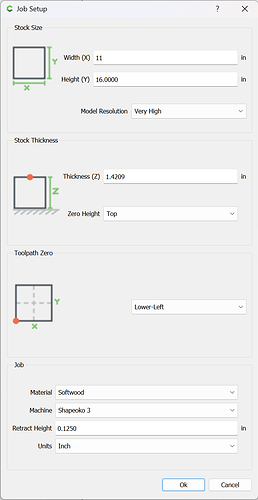
Adjust Model Resolution to “Very High”

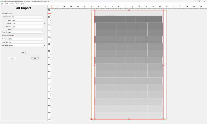
Verify the model’s dimensions:

Note that this model seems a bit different than the one before:

so the Stock Thickness has to be adjusted as well:

And also the width:

Select the auto-traced perimeter:

and offset to the outside by endmill diameter plus 10% — note that the model is over 1" thick, so a long-read endmill will be needed to model around it:

For the Finishing toolpath select the auto-traced geometry and select a tool which will be able to cut along the tallest vertical surface:

Note that a #102 may not be able to make that cut — it only has 0.5" of cutting flute length.

The resolution has been set to “Very High”. However, I am not seeing the Pro V7 3d rough tool path cutting across the board.

It worked on the smaller test cut we did last week.

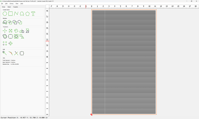
Bird house roof full size 11x18.c2d (380 KB)
Birdhouse roof full size 11x18.nc (73.0 KB)

You have doubled-up geometry:

Deleting that:

allows the 3D Roughing toolpath to be generated as expected.

1 Like

Thanks William for you help and patience. I am running on a deadline and need to get my 3D projects done by the week. I’ll get back to the tutorial after I am done. For the meantime, I will be using the Vectric VCarve Desktop to complete the projects.

This topic was automatically closed 30 days after the last reply. New replies are no longer allowed.