Brass 464 D6 cubes

Another ~1 day project so we’ll keep it short and stick to the details:

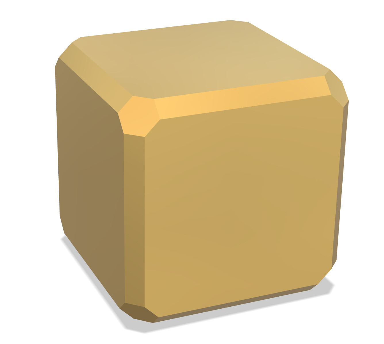
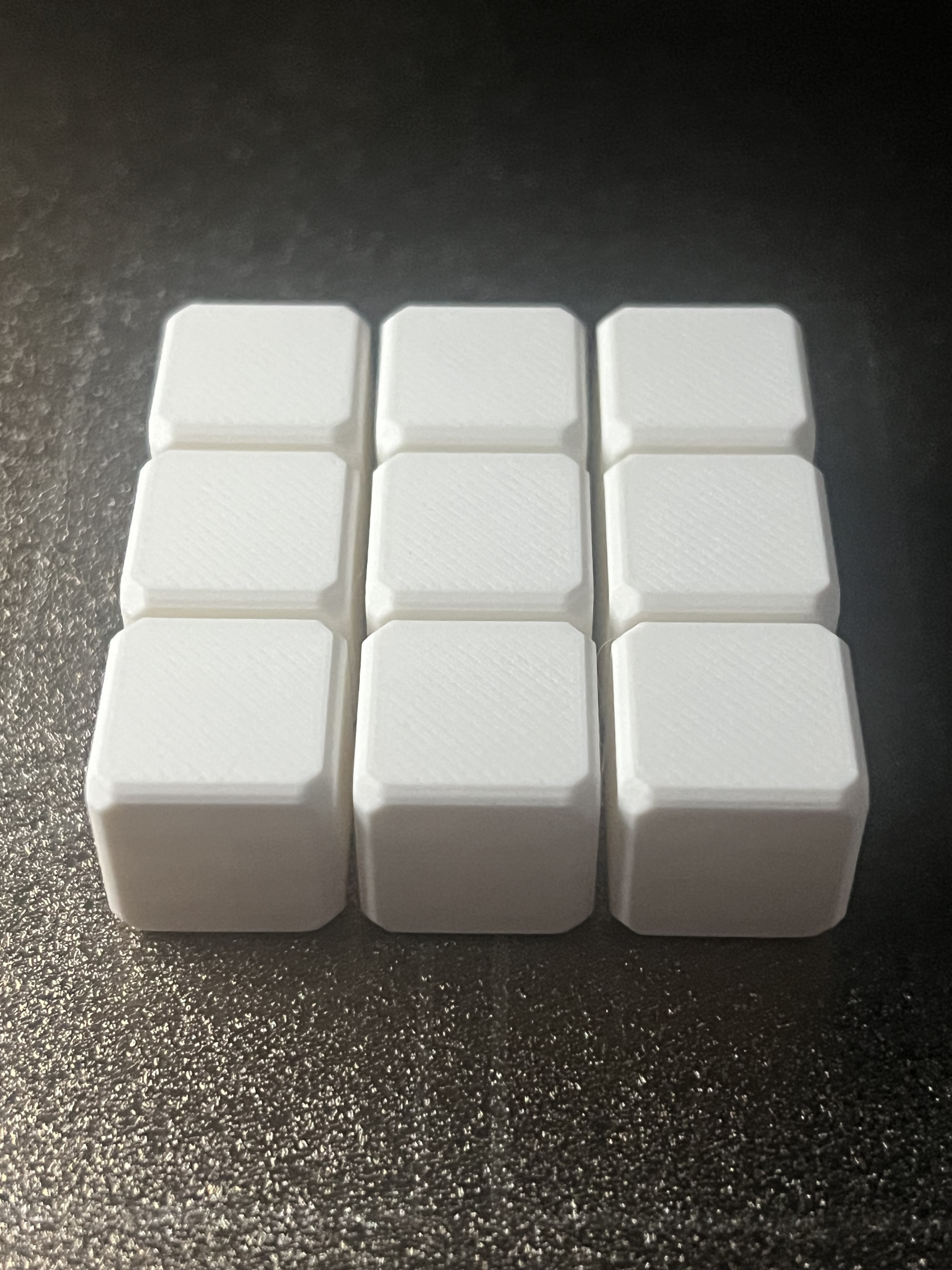
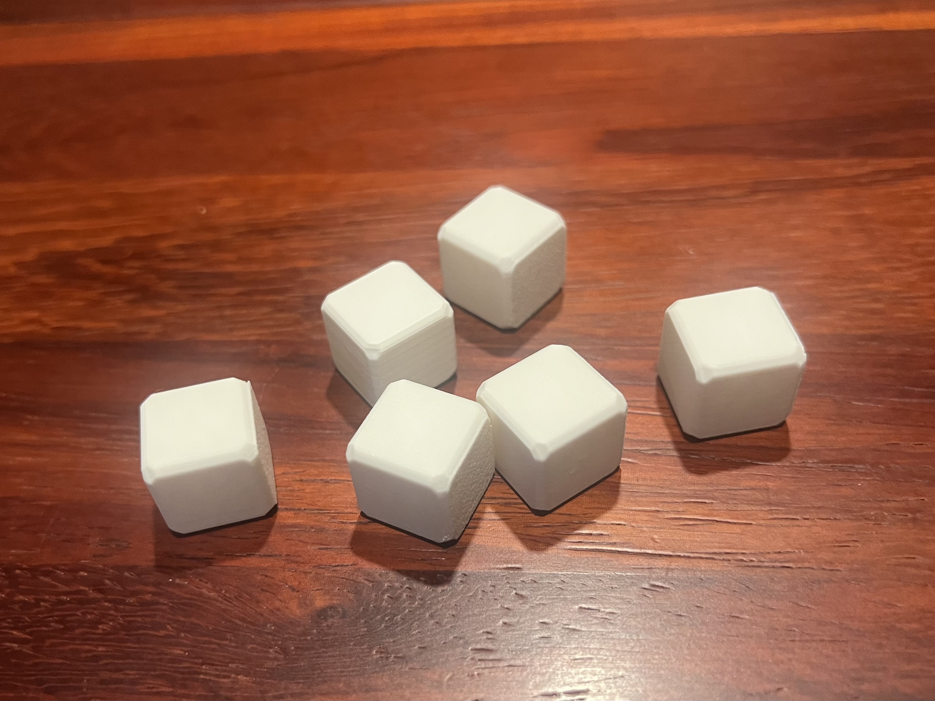
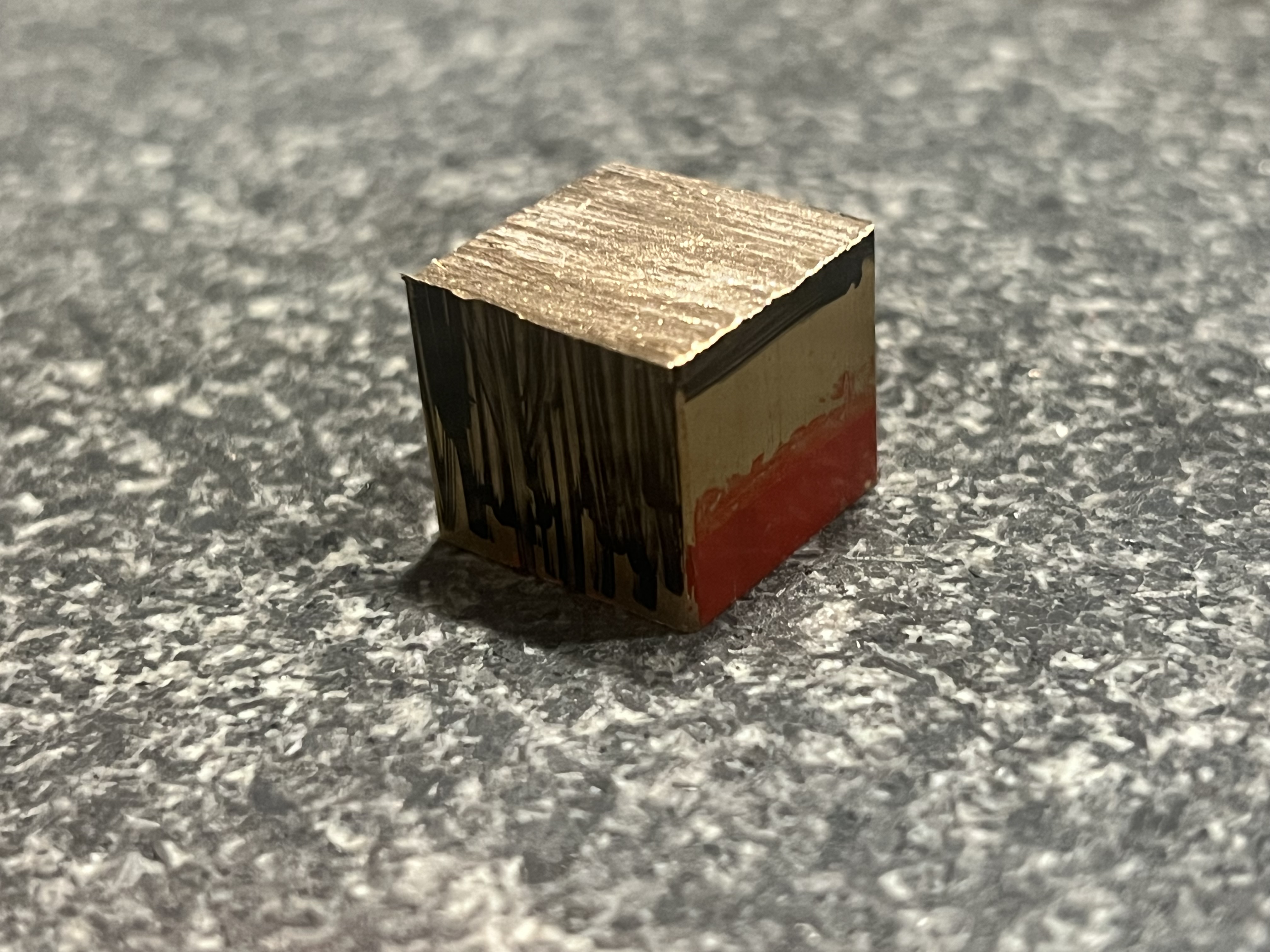
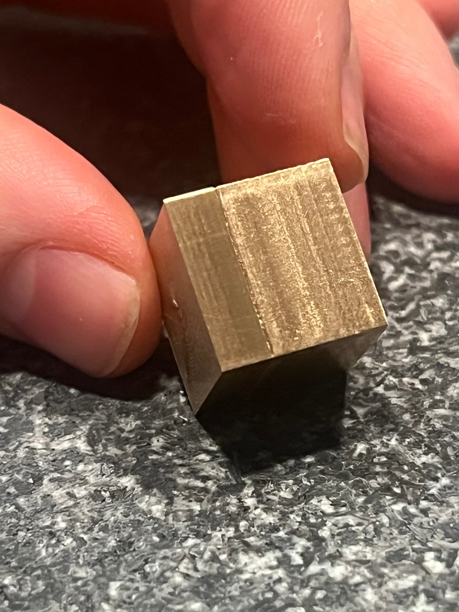
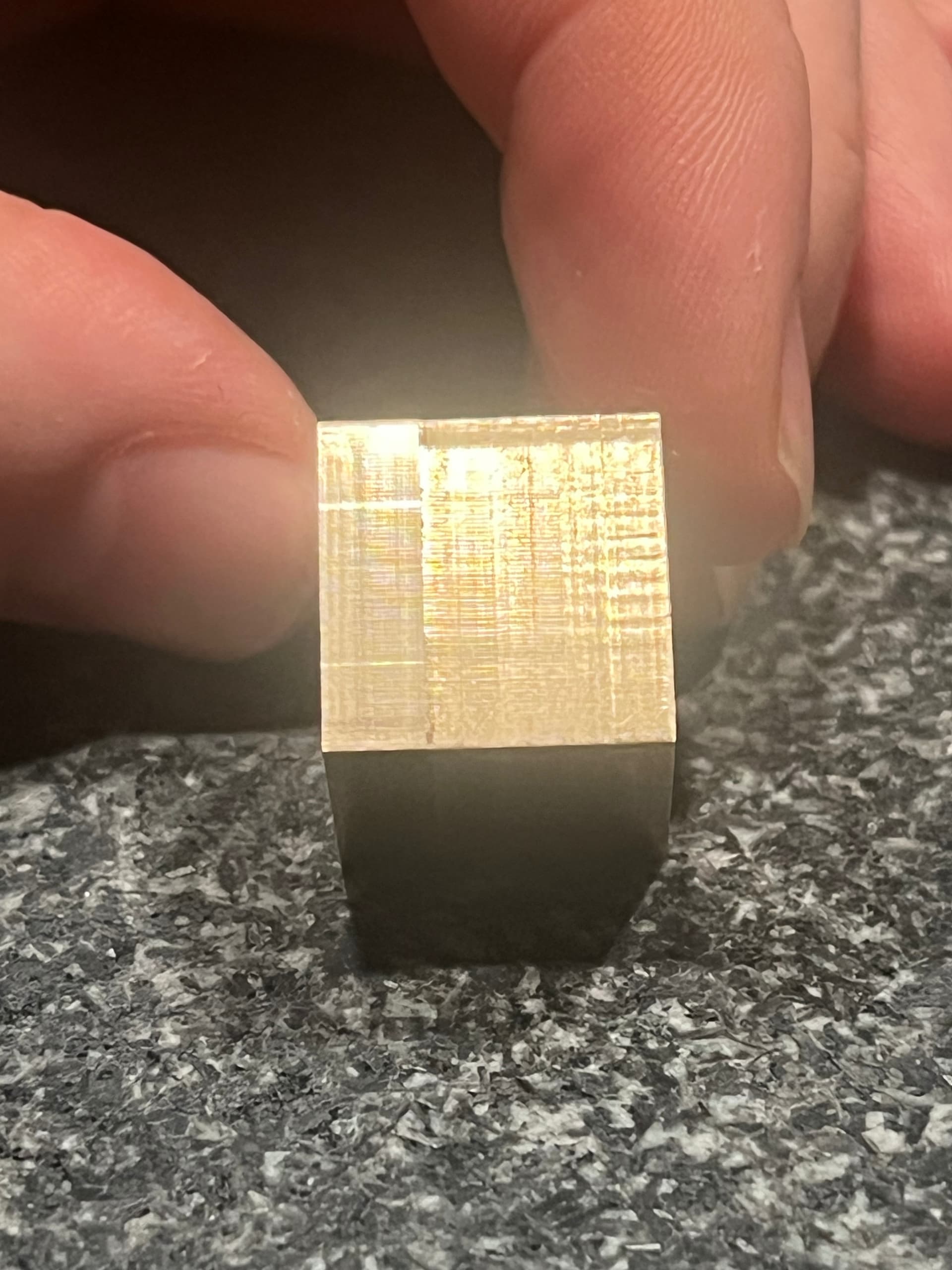
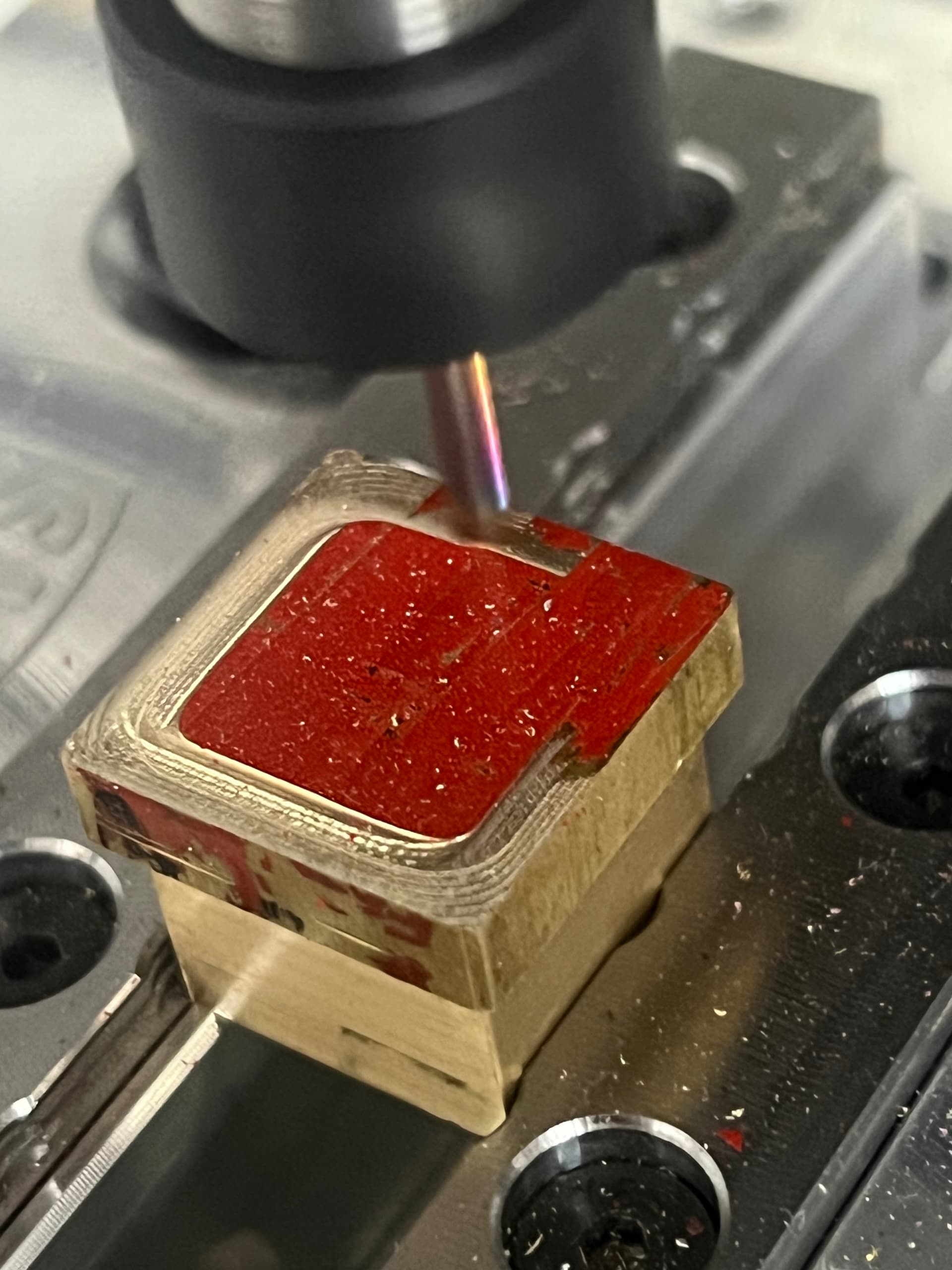
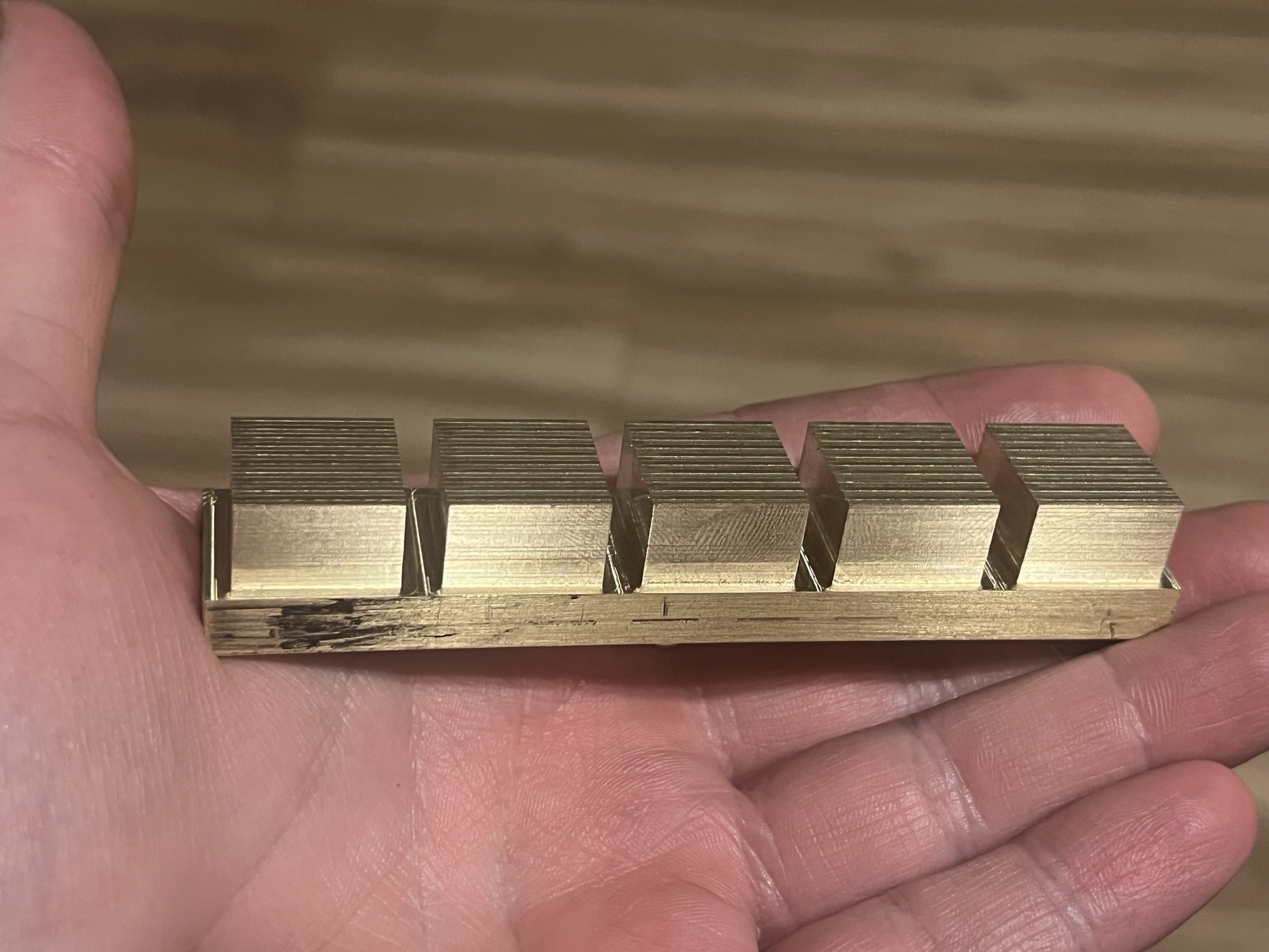
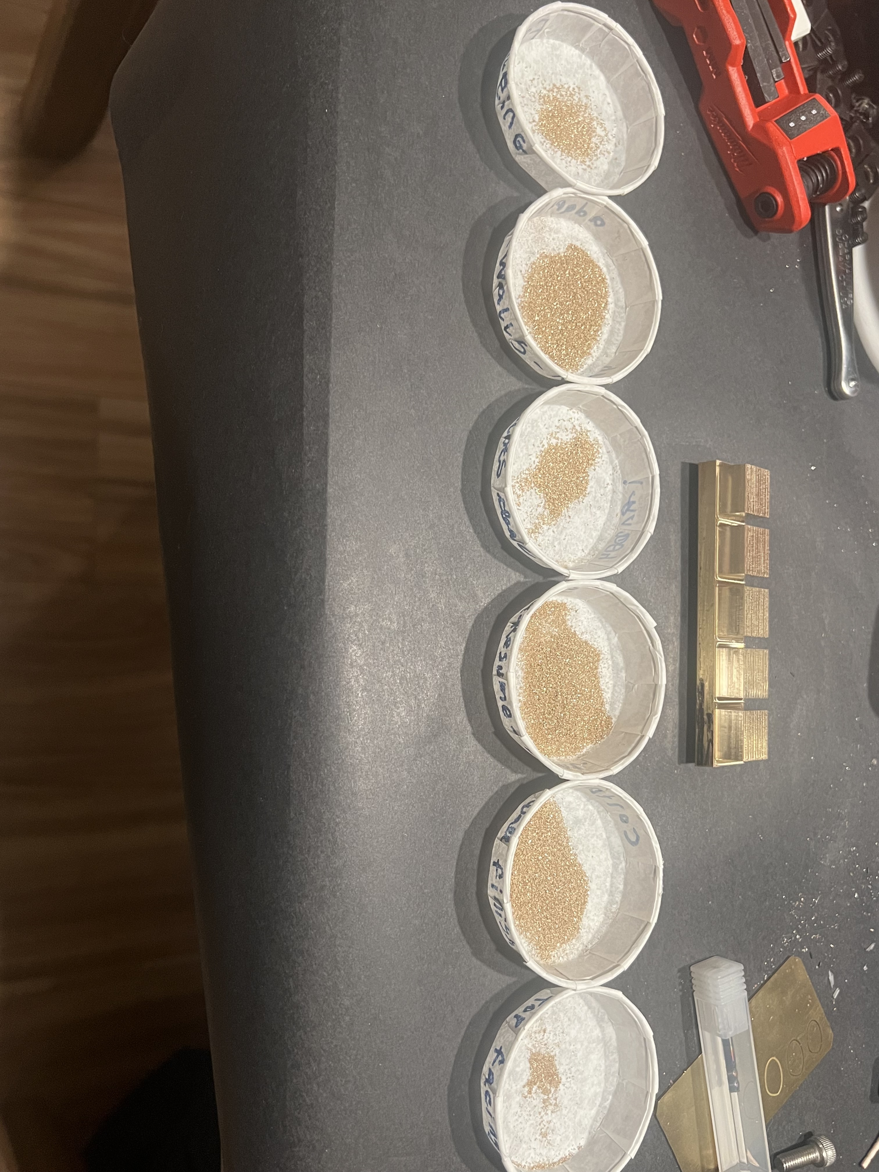
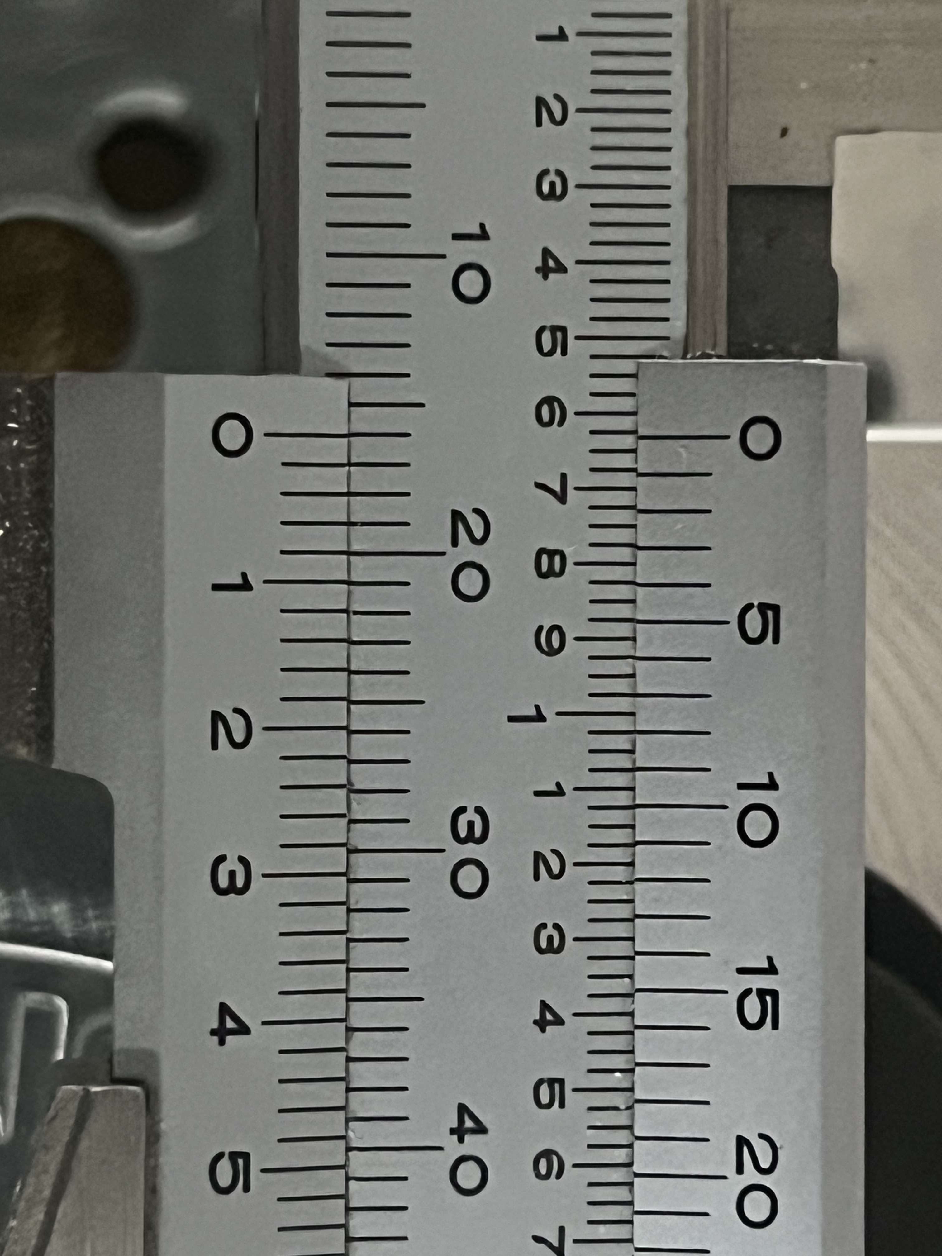
Goal: Make a set of 16mm cubes to serve as the base of a dice set.
Raw stock: 3/4"x3/4"x1’ 464 brass bar

Considerations:
Brass should be lead free as these will be high touch items. I could coat the items and use free machining brass to achieve reasonably low exposure but I want to work with 464 anyway so it works out.

Reference for starting point: Previous post from Maihyo DEYLAN CRAWFORD

Material sourced from McMaster-Carr:

Material 464 Brass
Shape Sheet and Bar
Appearance Plain
Thickness 3/4"
Thickness Tolerance Range -0.006" to 0.006"
Tolerance Rating Standard
Width 3/4"
Width Tolerance Range -0.006" to 0.006"
Yield Strength 22,000 psi
Fabrication Cold Worked
Temper H02
Temper Rating 1/2 Hard
Hardness Rockwell B55
Hardness Rating Soft
Heat Treatable No
Certificate Material Certificate with Traceable Lot Number
Specifications Met ASTM B21
Straightness Tolerance 1/2" per 10 ft.
Density 0.304 lbs./cu. in.
Surface Resistivity 39.9 cir. mil-ohm/ft.
Melting Point Temperature 1630° F
Modulus of Elasticity 15.0 ksi × 103
Thermal Conductivity 67 Btu/hr. × ft./°F @ 68° F
Elongation 19%
Material Composition
Copper 60%
Tin 0.8%
Zinc 39.2-39.7%
Warning Message Physical and mechanical properties are not guaranteed. They are intended only as a basis for comparison and not for design purposes.
Length Tolerance Plus
Length 1 ft.
Additional Specifications SDS
RoHS RoHS 3 (2015/863/EU) Compliant
REACH REACH (EC 1907/2006) (06/14/2023, 235 SVHC) Compliant
DFARS Specialty Metals COTS-Exempt
Country of Origin Germany, India, Mexico, Netherlands, South Africa, or United States
USMCA Qualifying No
Schedule B 740721.0000
ECCN EAR99

A lead-free alternative to 485 brass, 464 brass offers good weldability, strength, and wear resistance. It’s widely used for marine hardware, pump and propeller shafts, and rivets.

2 Likes

Further considerations: The alloy in the starting thread was not mentioned so I’ll assume it is free machining 360.
Comparatively 464 seems to be less machinable so I’ll start with backing off the starting recipe a bit and see how that goes.

2 Likes

And obviously for further reference there is the Brass Material Monday video

2 Likes

I like the look of chamfered edges and accidentally made a hexagon on the truncated corners.
Truncating and chamfering is an attempt to both facilitate rolling and soften the forces involved in corner collisions.

To make sure I like this in the hand, I printed a small batch. These will also help a lot in terms of visualization when coming up with a storage box.


I actually printed a few different edge and corner variations. Rolling light plastic is not terribly indicative of the feel when rolling solid brass…but as a comparative test it’s great.
From a few rolls of each variation, we can make some assumptions and decide which will likely roll best in brass.

4 Likes

We call this “progress” not only because a bar is roughly a cube. We also made progress in our hacksaw technique. The blade only wandered about 0.2mm cutting without a guide. That’s pretty decent compared to previous free hand cuts.

Kerf of a hacksaw would let me cut an additional ~3 dice compared to just cutting most of the way with the Endmill in the first operation.

That said, it’s just not worth the time. I’ll likely end up chaining/patterning the cube through ~8” of the bar. This piece is just to test and dial in the recipes and strategies.

2 Likes

Remember kids, model your fixtures (and your raw stock). Also don’t bother taking the time to render for a low effort forum post when visualizing is not the focus :upside_down_face:

Realistically though, modeling the fixture allows higher end CAM packages to verify allowances and belt/suspenders checks for tool collision. It’s cheap insurance once you’ve got your fixturing modeled once.

That said, I should have just drawn a square in carbide create and dropped two toolpaths on it (face and contour)…I would have been done with the first operation hours ago :sweat:

Sometimes(often) simple is all you need.

3 Likes

you’ll have to consider the other 5 operations per cube. how can you repeatedly reindex it, because surely you don’t want to set your zero 6 times per part right?

Maybe that’s a custom milled soft jaw for that vice?

2 Likes

I’ll probably do a second op soft jaw that indexes all 6 dice. Then it’s as simple as lopping the top off and finishing the last bit of the sides that I could not get to :slight_smile:

I’m still considering how I want to attack the chamfering and corners. The current plan is to set up the chamfering with a square end mill in a third and fourth operation.

The corners…I’m not sure about yet. Maybe that’ll be another jig, maybe it’ll be finished on not the mill. We’ll see. All I know is that I don’t want to deal with any stepping at all (for no other reason than personal preference)

This is very much just the base of the dice set, there’s going to be a fair amount of hand finishing and antiquing that comes later anyway so it doesn’t need to be perfect.

Some observations from cutting op 1 test:
I went with an adaptive clearing tool path to push things a bit. I pushed it a little too hard, the cut went ok but the machine wasn’t thrilled about it. I’ll explain what I think might have happened further down.

Here is all of the info I thought might be relevant from my adaptive toolpath. (Formatting and Imperial unit conversion done via copilot, so if they’re wrong blame Microsoft :robot: )

Recipe Information:
Preset 464 Brass
Spindle Speed 15278.9 rpm
Surface Speed 152.4 m/min (500 ft/min)
Ramp Spindle Speed 15278.9 rpm
Cutting Feedrate 1164.25 mm/min (45.83 in/min)
Feed per Tooth 0.0254 mm (0.001 in)
Lead-In Feedrate 1164.25 mm/min (45.83 in/min)
Lead-Out Feedrate 1164.25 mm/min (45.83 in/min)
Transition Feedrate 1164.25 mm/min (45.83 in/min)
Ramp Feedrate 635 mm/min (25 in/min)
Plunge Feedrate 381 mm/min (15 in/min)
Plunge Feed per Revolution 0.0249364 mm (0.000981 in)
Tool Information Value
Flute Count 3
Shank Diameter 1/8" (3.175 mm)
Cutting Diameter 1/8" (3.175 mm)
Length of Cut 3/8" (9.525 mm)
Coating DLC
Passes Information Value
Tolerance 0.08 mm (0.00315 in)
Optimal Load 0.4 mm (0.01575 in)
Minimum Cutting Radius 0.3175 mm (0.0125 in)
Direction Climb
Maximum Roughing Stepdown 1 mm (0.03937 in)
Fine Stepdown 0.01 mm (0.00039 in)
Minimum Stepdown 0.0001 mm (0.0000039 in)
- -
Notes from testing As a “safer” aggressive cut I have since reduced Optimal load to 0.3mm and Maximum Roughing Stepdown to 0.5mm

Bonus Poll! It’s great to guess and check yourself against the hive mind. Vote to see the results (don’t worry about perception, your vote shouldn’t be visible to anyone)
And most importantly, if you feel particularly confident about your answer, please explain it in a reply. I know I’d appreciate it :grin:

Feeds and speeds opinion
  • Woah, maybe take the foot off the gas :face_with_peeking_eye:
  • You can go faster, pedal to the metal :racing_car:
  • Juuuuust right :sunglasses:
  • I do not know but I am interested to find out :slightly_smiling_face:
  • I am RichCournoyer. The geometry simply cuts itself from the stock under my gaze, no recipe necessary. :goat:
0 voters

And lastly, some photos of the chatter on just one side and some thoughts on why it may have happened

Lightbulb moment, my wife asked if the cube was crooked

First off, there were no good reference edges to work from. The bar is extruded and saw cut so I figure the best I can do is create the reference in the first operation.

While I pushed the little nomad to what I would consider “uncomfortable”, the sound was actually OK. Not great, but not terrible.
That is until it got through the facing operation and started contouring down around the edges.
Every time the cutter engaged on the left of the cube, I got a bit of chatter. I wasn’t really sure why considering every other side was sounding ok. The chatter wasn’t bad enough to stop and regroup so I figured I’d just let it finish the 4 minute operation.
Then about half way down the cube, the chatter stopped and the cut was beginning to sound…lighter. This again was odd but I was just thankful for the noise to be gone and finished up the cut.

Here is a photo of the obvious chatter marks, including the distinct lack of chatter midway down:

I’m sure if you know what you’re doing, the cause is obvious to you but I’m no machining master. Hell, I’m not even a journeyman :see_no_evil:
It wasn’t until my wife asked me if the cube was “crooked” that I think I figured out what happened here. The cube, when sitting on the raw cut edge is most certainly crooked:

Lo and behold, the chatter marks are only on the side where the less than perpendicular raw stock would have caused a greater than expected cutter engagement. I think this is demonstrated well with this grossly exaggerated little drawing:

From the front we can see that the blue “Endmill” on the right sees much less material than the orange “Endmill” on the left, even though they follow the same path (EG: they are the same distance from the final sketch geometry)
But we can also see that this condition lessens as the new “wall” of the removed material approachs perpendicular to the raw stock corner.

In this case, it does not matter. The newly exposed geometry is going to be square and parallel to the bed which will serve as a reference to finish the rest of the cube. In short, I think I just caught a bit of dumb luck…I don’t mind being lucky every now and then :beers:

That’s all the cutting I can do for tonight, let me know if you agree if my theory or if I’m missing something else that could have caused chatter on one side of a cube.

And hey, If you got this far, thanks for reading (Hi Julien :wink:)

2 Likes

Thanks for teaching me something new about the formatting features for posts. I’ve been here more than 5 years and I’ve never noticed the “Hide Details” drop-down tool, nor seen anybody use it. And there it is, hiding in the little gear menu:

2 Likes

I like the format and detailed info! I know climb cutting seems to be easier on the spindle, but I feel like it results in worse finish compared to conventional? I don’t machine metals so I don’t really know the proper way to mill it. Glad you found the root cause of the chatter. I was racking my brain on why it would do that on only one side and then I kept reading and you figured it out haha.

2 Likes

Finished up the top side/second operation of the test piece over lunch. So many easy lessons learned!

First: The chatter was certainly caused by the stock not being normal to the bed. I am certain of this because the little jaw inserts for my modular vice were just barely able to be wiggled by hand.
Which is waaaaay to much wiggle for any metal cutting, let alone aggressive cutting :sweat_smile:
Lesson: Double check your work holding. All of your work holding.

Photo for reference, the little black inserts were not tightened to spec:

Second: I backed off the aggressive cut just a bit and things went much smoother. I figured the biggest factor was limited torque, so I cut the roughing depth of the adaptive by half. My weak assumption is that depth of cut has a largely linear relation to required spindle torque.
With that in mind the goal was to go from “uncomfortable” to “probably fine” :slightly_smiling_face:

I also backed off the optimal load from 0.4mm to 0.3mm. That’s 25% shaved off but I don’t have any intuition as to how that should affect required spindle torque for a given cut (If you do, feel free to chime in and let me know!)

This resulted in much more consistent sounding cuts all through the operation and a much much better surface finish…how much of that is related to proper work holding, the world may never know :person_shrugging: (probably a lot though…)

Here is an example of the the comparative surface finish from both operations:

And a high reflection shot to really put my shame on display :melting_face:

I think it’s worth showing these kinds of results because at the end of the day…this is a perfectly usable part. The surface finish is purely aesthetic in this case and it passes the fingernail test beautifully (meaning I cannot feel the difference in finish when scrapping a fingernail across the surface)
The fact that I can achieve this as a relative novice in my garage over lunch is nuts. I’ve dabbled on and off for quite some time and that experience means a rarely break a tool these days but I can only imagine what someone doing this 40+ hours a week day in and day out could churn out in a day. [1]

Moving on, the flip operation was obviously misaligned but only along one axis. This makes sense considering the x and z axis were constrained by a fixed jaw that did not move.
With no stop or anything repeatable to speak of in the y axis, it was up to me to really dial in that new zero…which I did with reckless abandon because this is a test cut, I don’t care all that much.
Still, don’t expect to do a perfect flip and second operation without careful consideration for how you plan to hold your work and/or rezero :slightly_smiling_face:[2]

Lastly, here is a fun photo showing just how skewed the first op really was:

Later on I should have some “real” results to show for my efforts and we’ll go into how I plan on work holding and such for multiple dice at once.[3]


  1. Ok, you don’t have to imagine. There are a few folks on the C3D forums that demonstrate this perfectly and I’m totally not jealous at all about that…not a bit…maybe a little. ↩︎

  2. I did manage to get it within about 0.2mm though. Not terrible, especially since this will be post processed regardless. ↩︎

  3. Another fun formatting feature for ScottsdaleSteve, footnotes! for when a post is already too long but I still have more to say :speaking_head: ↩︎

4 Likes

Super quick update, I focused a lot on dimensional accuracy and surface finish. Not because it’s terribly important but because I wanted to actually tackle intentional tool strategies…instead of my usual approach of dropping an adaptive clear on it and hoping for the best :sweat_smile:

There were some interesting and unexpected results from some of the strategies employed. In hindsight the issues are obvious but they deserve a proper explanation I think :slightly_smiling_face:

I’ve also been convinced to be a bit more methodical in my approach. This time around I cleared chips after every op and collected them at the end of the op.
I hope some good magnification on the chips can provide a little insight as to what worked and what didn’t in the strategies I tried.

I’ll try to get the results together in the next day or two but here’s a small peak:

They are meant to be 16mm exactly. Not bad all things considered

6 Likes