Brushless Makita Mod (unsupported)

Might pass the value through an exponential filter. IE:

avgPulseLen = 0.85 * rawPulseLen + 0.15 * avgPulseLen

might even change that to:

avgPulseLen = 85 * rawPulseLen + 15 * avgPulseLen

and just keep in mind that the average is 100 times the actual value. This prevents floating point math. I am using this value to check a look up table for the RPM so as long as I scale the values in the lookup table accordingly it wont be a big issue.

1 Like

Sounds like a computationally efficient and sensible plan to me. I suspect you’ve done quite a bit more programming on the Arduino type CPUs than I have.

1 Like

No actually. I do however work with Real Time processes in the telecommunications land. Things like you have 500 microseconds to update some critical value otherwise someone’s phone call hangs up. I have to assume every single phone call is someone on the phone with Emergency Services so disconnecting them is REALLY bad. As such I spend most of my day thinking of how to squeeze every last cycle out of a server.

2 Likes

Well I clearly forgot how to Math last night. Have to divide by 100 to keep the equation balanced. Division is worse than floating point multiplication.

Multiply by 0.01 :slight_smile:

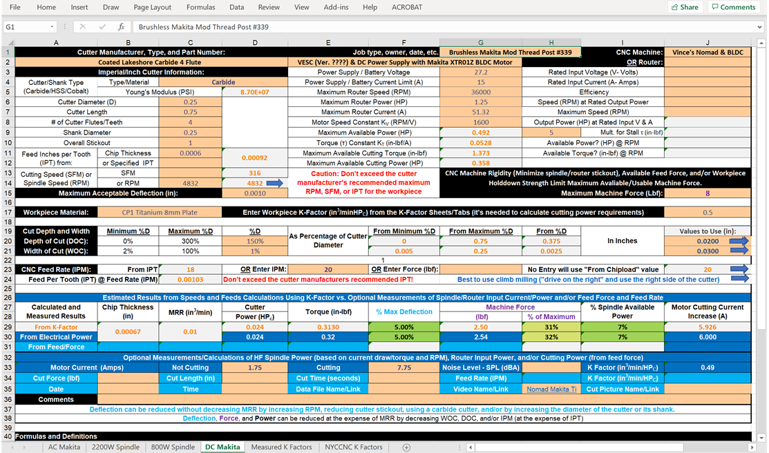
OOPS - I discovered some errors in the recently posted SFPF workbook’s “DC Makita” Speadsheet. Here’s what the corrected version looks for your “Nomad Makita VESC Titanium” video.


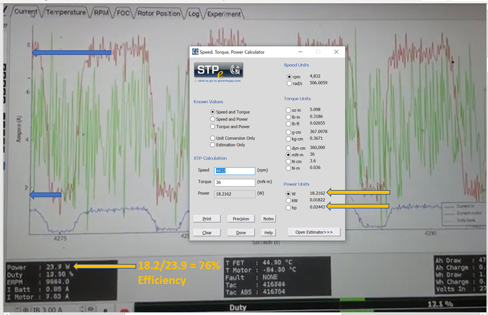
Using cutting current increase is the most accurate measure of cutting torque/force and power because it’s directly proportional to torque and isn’t impacted by inefficiencies.

So I remembered I had an old 3d printer with a RAMPS board. Attached to the RAMPS board is a Arduino Mega. It is overkill for the job, but it is 5V and will work as a replacement for my Nano till the actual Nano Every gets here.

I tried adding exponential filtering to the pulse length values. Unfortunately for it to be effective at preventing the minor RPM jumps it was causing about five seconds of delay. Hopefully it is just noise on the line and shortening it will cause it to go away. If not I may revisit this.

I have setup a PID control as well. Without the tach working though it doesnt do much. So next step is altering my wiring harness… again.

2 Likes

Tach is working. Just need to hook up the PPD line to the VESC and see what happens. That is a task for tomorrow though. Kind of worried about the fact that my PID controller is sending a PPD signal to another PID controller on the VESC which is actually what is controlling the RPM.

After that I am going to need to finish my design for the housing. I want to make it sealed so that no chips can get in. I am thinking of making the top out of Aluminum and replacing the stock heatsink on the VESC with it. Issue is I have never machined aluminum and my machine is in my apartment. Need to keep noise levels down. My enclosure is good, but not sure if it is that good yet.

1 Like

Well I hooked everything up and the motor just hums. I am at a loss.

Is it stalled? Sometimes motors looking for sensor feedback can cog and get stuck between motor poles.

Hmm. I do not think that is the issue, but I think I might try running it sensorless to see if that might be part of it.

Mad Scientist Moment:

6 Likes

Good news is I got the motor working with the VESC using PPM. The hall sensors were the issue. Running it sensorless and it started right up. Bad news is while trying to figure out why it wasnt able to use the sensors magic smoke came out of my powersupply. Didnt even blow the fuse. Before my PS died it looks like the VESC tried to push 160amps into the motor. I think I am just going to run it sensorless. LOL

3 Likes

Awesome work!
What power supply were you running?

A Mean Well 24V 14.6A supply. Pretty good quality. Already have an exchange on its way as well as an inline fuse. Hopefully that will help.

Indeed, normally a decent supply. They have short circuit output protection too so it shouldn’t have failed on over-current.

Does the VESC do active braking of the spindle? If so then you might want to turn that off or put some sort of crowbar / shunt circuit in to prevent overvolt-ing the PSU during spin down.

1 Like

It can do active breaking but it SHOULD have been disabled. Not sure how many people disable it with the VESCs because they are mostly used on small electric vehicles (bikes, skateboards, scooters, etc) so no clue if it was actually working.

Here’s what one of the motor winding currents look like when my unloaded 18V Milwaukee BLDC router starts, runs, and stops. I imagine that the battery absorbs much of that braking energy (which needs to go somewhere). A diode in series with the VESC’s input power line would probably save the power supply, but might break the VESC - especially if it’s not rated for twice the motor’s operating voltage. So a big voltage clamp of some type (near the VESC) is probably the way to go.

2 Likes

Nice data.

Yes, a power sink of some sort is what’s needed for active braking, things like the VESC are likely to do this both for tool safety where fast stops are required and for battery life through regen braking on one-wheels and things like that.

As you say though in most cases that’s the battery, because thats the design intent and they can sink a lot of power for short periods. On a bench supply it gets more complicated as you need to put some power dissipating components in with those over-voltage triggers.

1 Like

The sensorless motor config I’ve been running has everything enabled and it hasn’t been an issue running the VESC tool manual controls. I have been able to get the vesc to throw an over voltage fault but didn’t fry anything.

You can set the speed controller to not allow braking, brake max current to zero, battery regen max current to zero.