It’s not a total loss and not being able to trigger a fault isn’t a deal breaker.
The brushless Makita is much more powerful and tweakable than it ever was with the stock controller. We can still see the realtime current on the computer and if you get the bluetooth module then you can monitor/log on your mobile phone.
Thank you for your hard work on this project and its still heading in the right direction.
I’m just a bit discouraged. It’s like finding out that the kid from your group project didn’t do his part that your part relies on. You then scramble to make something that at least sort of works so you don’t fail because of someone else.
I’m going to get it working this way and then see if I can port that library to the V5 firmware.
Well I managed to fry my prototyping Arduino Nano after 8 years. Probably reflashed it one too many times and it just kind of stopped wanting to flash. Just ordered a new one. That will be here Thursday.
Before I did though I was able to read the PWM pin and map the result to the correct RPM. Unfortunately the noise on the PWM signal can cause the PWM pulse length to fluctuate 4 to 6 microseconds. When I tried using 250 RPM steps for the RPM range the difference in the pulse length from one step to the next was 6 to 8 microseconds. That is too small for the noise levels so I had to go with 500 RPM steps. With 500 RPM steps the difference in the PWM pulse length from one step to the next was between 12 and 16 microseconds. Hopefully the noise levels will go way down once the arduino and the Carbide Board are in the electronics enclosure together. If it is, I will revisit the step length.
Now that I know the requested RPM I need to get the tachometer working (should be super easy) and then feed the current RPM and requested RPM through a PID control loop to spit out the correct PPD pulse length to send to the VESC.
How are you reading that PWM input on the Arduino?
i.e. a hardware counter, an interrupt service routine etc. ?
If you’re pulling it out in software to then send it to the VESC controller, as the speed shouldn’t change very often (we’re not doing tapping here) it’s probably safe to do a bit of de-bouncing on that input with a moving average (or a Kalman Filter if you like maths).
It is interrupt based. When the signal rises I set a time variable and switch the interrupt to falling. When the signal falls I subtract the time variable from the current time to get the pulse length and switch the interrupt back to rising.
My main loop only blocks the interrupts when it reads the pulse length from the variable the interrupts are messing with into another variable that the loop can mess with. This should take only a few cycles (if that) of the processor. This could be what is causing the variance in the reading I suppose. If that is the case, increasing the amount of time my main loop poles the pulse length variable should cause the noise in the value to increase. Currently I am only poling once per second, but planned to up that to 10 times a second or more. I did go with the Arduino Nano Every to replace my Arduino Nano. It runs at 20Mhz instead of 8Mhz like the Nano. I will see if that makes a difference.
As for filtering, my only concern is going from 0 RPM to literally any value. GRBL only gives the spindle so much time to get up to speed before continuing on with the G-Code. In my testing this was only about two seconds. If I am averaging the last say 5 values, that is half a second chopped off that spin up time. I could always sample faster, but that might cause more variance in the values.
Maybe use the VESC tool to set/control speed (which isn’t likely to change much/often) and just have CM or whatever turn the spindle on/off? Sorry if that’s a stupid question - I’m not a software guy.
If I recall correctly, you can build a Kalman filter for an arbitrary number of dimensions, you just need to define the input vector size and transition matrix consistently; https://www.kalmanfilter.net/kalman1d.html
However, there are likely much faster and more appropriate library functions for C++, I keep thinking like I’m using Python and have CPU cycles to burn
I recall some discussion about spin up time and having to do nasty things to the GCode if your VFD was taking too long to spool up. Best avoided if possible yes.
and just keep in mind that the average is 100 times the actual value. This prevents floating point math. I am using this value to check a look up table for the RPM so as long as I scale the values in the lookup table accordingly it wont be a big issue.
Sounds like a computationally efficient and sensible plan to me. I suspect you’ve done quite a bit more programming on the Arduino type CPUs than I have.
No actually. I do however work with Real Time processes in the telecommunications land. Things like you have 500 microseconds to update some critical value otherwise someone’s phone call hangs up. I have to assume every single phone call is someone on the phone with Emergency Services so disconnecting them is REALLY bad. As such I spend most of my day thinking of how to squeeze every last cycle out of a server.
Well I clearly forgot how to Math last night. Have to divide by 100 to keep the equation balanced. Division is worse than floating point multiplication.
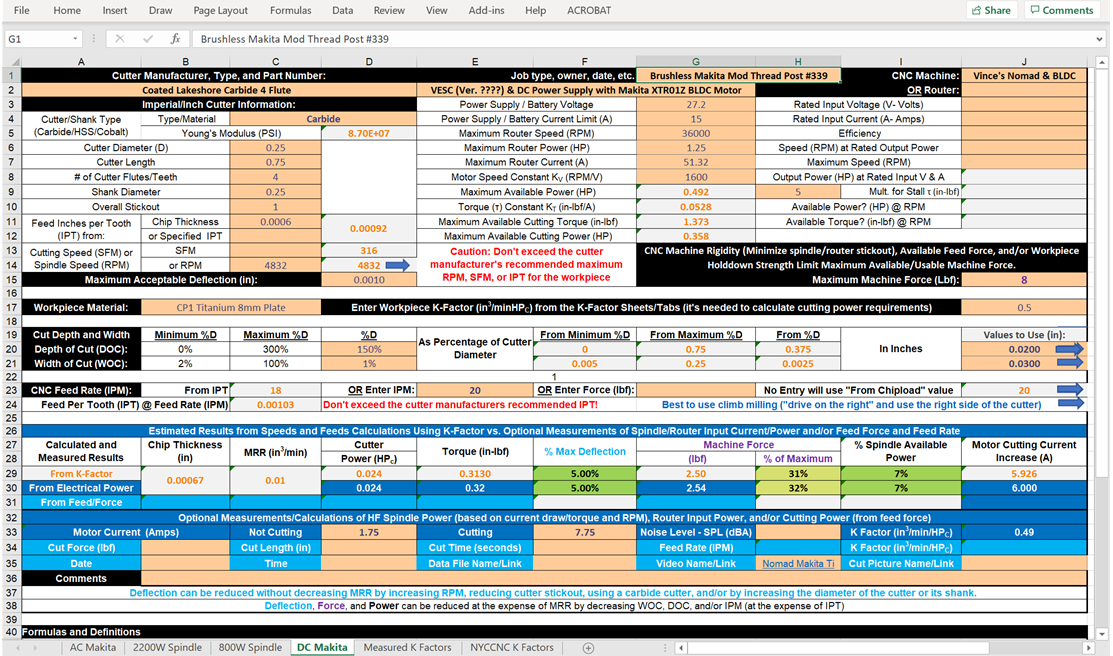
OOPS - I discovered some errors in the recently posted SFPF workbook’s “DC Makita” Speadsheet. Here’s what the corrected version looks for your “Nomad Makita VESC Titanium” video.
Using cutting current increase is the most accurate measure of cutting torque/force and power because it’s directly proportional to torque and isn’t impacted by inefficiencies.
So I remembered I had an old 3d printer with a RAMPS board. Attached to the RAMPS board is a Arduino Mega. It is overkill for the job, but it is 5V and will work as a replacement for my Nano till the actual Nano Every gets here.
I tried adding exponential filtering to the pulse length values. Unfortunately for it to be effective at preventing the minor RPM jumps it was causing about five seconds of delay. Hopefully it is just noise on the line and shortening it will cause it to go away. If not I may revisit this.
I have setup a PID control as well. Without the tach working though it doesnt do much. So next step is altering my wiring harness… again.
Tach is working. Just need to hook up the PPD line to the VESC and see what happens. That is a task for tomorrow though. Kind of worried about the fact that my PID controller is sending a PPD signal to another PID controller on the VESC which is actually what is controlling the RPM.
After that I am going to need to finish my design for the housing. I want to make it sealed so that no chips can get in. I am thinking of making the top out of Aluminum and replacing the stock heatsink on the VESC with it. Issue is I have never machined aluminum and my machine is in my apartment. Need to keep noise levels down. My enclosure is good, but not sure if it is that good yet.