Who said we were not impressed. LOL. I just wanted to see this thing sustain a lower than stock RPM while doing actual work. Ill be joining you soon. I have been making noobie mistakes making a waste board.
2 Likes
It looks like you did it right to me. HSMAdvisor apparently uses 0.5 cu-in/min/HP for it’s toughest grade of Titanium. But K-factors are likely dependent on cutting parameters, conditions, and tools. That’s why it makes sense to keep track of the details (like the workbook enables). It’s easy to add sheets to reflect details of your latest cuts.
What does Lakeshore recommend for that endmill? Guhring has some that will support 430 SFM with Titanium. As you know, higher speeds take less force. IMO a higher speed spindle on the Nomad is a good move!
Maybe you don’t need to water cool it after all (little power = little heat)
Can the software provide a “real time” display of motor torque? Is it in the .csv file? What all is in it? Nice to be able to see stuff in “real time” and get some more useful “real world” material K-factors! ![]()
2 Likes
I’m definitely going to have to learn how to use your workbook better and start logging things.
Lakeshore actual recommends a 100-250 sfm for soft Titanium and 80-220 for hard with a 0.0004-0.0009 chipload for that general purpose endmill. They also recommend coolant. Titanium is a game of heat management and when your doc is small then things get even tougher.
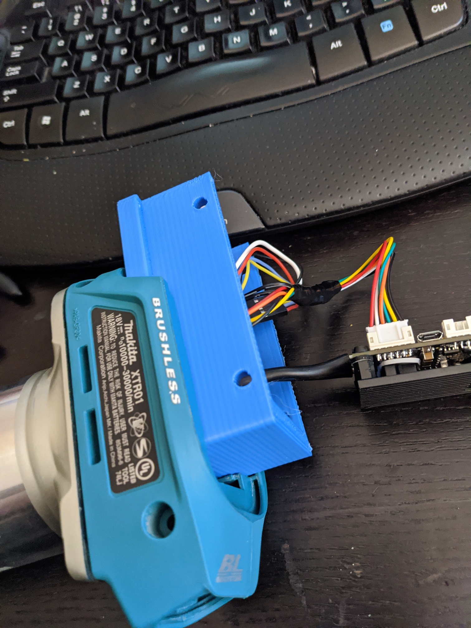
It will need some type of cooling with heavier cutting and more mrr. Fanless was just a way to force myself to make a custom body.
The Vesc Tool software has a 0-95% duty cycle gauge that updates realtime. That gives a pretty good idea of what kind of power you’re seeing. It would be nice to figure out how to smooth the data a bit. I’ll get back to you on how the csv file is configured but I do have it saved for that cut.
3 Likes
3 Likes
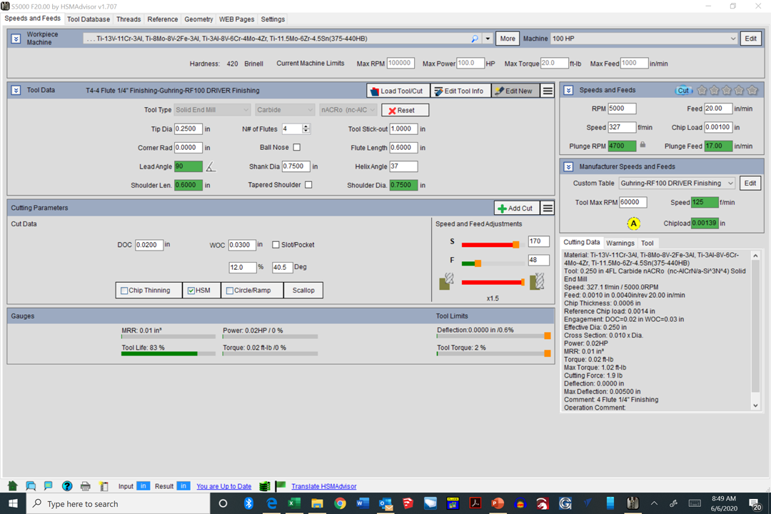
This might make development easier: SparkFun IMU Breakout - MPU-9250
Invensense says, “Note: The MPU9250 is Not Recommended for New Designs” That must mean that this model has a newer version.
2 Likes
The VESC has three different compatible external imu options and I liked that one because it has a nice plug for i2c connection.
The sample rate looks to be pretty high due to the fact that usually these are used for self balancing applications like a diy One Wheel.
1 Like
Wow, it’s a lot more than just an ESC.
1 Like
So I just connected my arduino to the PWM pin and tried to read the duty cycle. The pulse length is coming up as everything from 0 microseconds to 82043 microseconds. When I take the same code and attach it to the PWM out of another arduino I get a solid 500 microseconds +/- 3 microseconds.
I am not sure if I am getting a shit ton of interference from somewhere or what.
Figured it out. Had the unshielded PWM wire running next to the X and Z stepper motors. They were giving off a shit ton of interference. Looks like I need to use shielded wire. Just means I need to rip some USB cables apart.
In other news the Carbide board’s duty cycle is not linear which means I need to go back to an RPM map.
So, that’s not a nice metric tonne of interference then? 
2 Likes
Ugh… This is going to take MUCH longer than I thought. The stable version of the UART control library is for firmware version 3.40. The development version of the UART control library is for the firmware version 4.2. The version of VESC we have installed is version 5.1. There were major changes between them all.
I can implement PWM to PPM on the Arduino board, but that does not allow for setting the RPM precisely.
I can’t help but wonder what’s the difference in driving a vfd to accurate rpms. Can we do ppm to pid speed control?
At least we know it works well with USB connection.
Just picked up an Uno to play around with. This arduino stuff is pretty interesting.
Yes. The PPD ‘app’ on the VESC has PID Speed Control options. There is just no feed back to the arduino. This means we cannot set it accurately. I already made a version of my code that outputs PDD. Going to mess with it tomorrow.
Actually… The motor has Hall Effect sensors. I could potentially read those on both the arduino and the VESC. This would allow the arduino to know the RPM and adjust the PDD signal to compensate.
Only issue is the 3.3V arduinos I ordered are useless at that point as the hall sensors, the PDD input, and the Carbide Board are 5V.
Thoughts on borrowing a trick from SuperPid and use an optical infra-red sensor that is pointed
at the router output shaft?
Would there still be a way to fault trip a feedhold pin?
http://replicantfx.com/grbl-custom-rpm-to-pwm-mapping-custom-cnc-part-5/
The Hall sensors are more accurate and yes there can still be a fault pin. If the actual rpm is too far off from the requested rpm for too long I can trigger a fault.
Added RPM reading to my PWM to PDD code. I need to map the M3 S_____ RPM to the Duty Cycle of the Carbide board. Then map the PDD time to RPM value of the VESC. Then add a PID feed back system to adjust the PDD to get the RPM to match the requested RPM. I also need to figure out when to throw a fault which is harder to do than I first thought.
Do you plan to get and display motor current too?
Can’t. The VESCuart library doesn’t work with the lastest firmware yet. So I can’t get any data directly from it. It might as well be a dumb ESC right now.