That’s definitely an interesting thread, even if only for the pics of Vince’s work.
Reading through it, I’m more and more thinking that a real time spindle torque / power readout for the Shapeoko and Nomad is worth trying out.
I’ve got my RS485 to TTL converters, water temp sensors, flow sensor and real power meter to wrap around my water cooled spindle all ordered and on their way from China.
Unfortunately, not over here, Dr Evil only had ship from China, delivery mid July versions of that unit with the CT and the RS485, eBay had lots of them, all SpeedPak from HK so I ordered one from there.
I also found these which might be a better long term option to add to the DIN rail in my switchgear box.
So after discussing the best way to accurately set the RPM with a few people who know more than I it sounds like the best way is to implement a PWM-to-UART arduino board. This board would read the duty cycle of the PWM output from the controller. It would then consult a map of duty cycle to RPM values. It would then push the RPM value to the VESC over UART. It will also have a fault pin that gets pulled to ground when there is an error. This can be used as an E-Stop. This solution would also be control board agnostic. Once those two main features are added I will also look into a method of adding direct temperature monitoring.
For anyone who cannot wait for me to make that arduino thing ( -cough- @Vince.Fab -cough- ) those same people who know more than me recommended getting one of these instead of the RC Circuit I posted:
and passing the out put through a voltage divider made up of a 6.8k ohm and a 3.3k ohm resistors. They are used for interfacing with VFDs that want 0-10V. The voltage divider will knock that output down to 3.3V.
Are you sure? Doesn’t the housing get warm when you run it? The stator must be rigidly attached to the housing (by aluminum struts?) for the thing to work - right @Vince.Fab? Aluminum is often used for heatsinking electronic components because it conducts heat so well. Adding heat sink compound between the motor and its aluminum mounting bracket and mount’s aluminum Z axis interface would help keep the motor cool. Increasing the size of the aluminum contact areas could help a lot, as would adding cooling fins (and a fan) to the motor mount. Water cooling may well be overkill. Can Fusion 360 do thermal analysis @Julien?
Water cooled is not overkill, I wanted to integrate heat exchangers with the controller and power supply as well. Hopefully a bigger PS will be able to run both the Nomad and Spindle together. Also in the eyes of thermal management to regards to precision and consistency, control the heat - control the world.
There is a “thermal study” option in the “Simulation” world in Fusion360, but I never used it (and it seems like it requires a thing called “cloud credits”, which led me to close than window really fast)
Yep, look at all the work Hermle puts into managing thermal expansion coefficients, oversizing drives and calculating expansions in their VMCs to get the serious accuracy.
The way the router is currently cooled, the impeller at the bottom of the spindle sucks air in from the top, past the electronics, and around the stator core. I am pretty sure that Makita did not want the external aluminum housing to be in contact with the internals to reduce the chance of electric shocks. On a cordless tool, there is no way to tie the housing to Earth ground. And with a router all it would take is some idiot using the thing to cut aluminum (please note I plan on using it to cut aluminum so I am calling myself that idiot LOL) and some chips getting sucked in through the top.
@Vince.Fab is planning on milling an entire new all aluminum housing for his water cooling adventures which will hold the stator core directly.
If fault_code is anything other than 0 there was a fault. I am going to be spitting all this data out on the serial port once a second as CSV data. Are there any easy to calculate stats you guys would like me to derive from this data as well? Please include an equation. Also keep in mind that this is going to be run from probably an Arduino Nano so please keep the most complex operation being division.
There’s normally no conductive path to earth from the batteries. That’s why they’re inherently safer than AC powered devices. In addition, their voltage levels are usually too low to be lethal - even in sea water.
My guess is that either they didn’t want the housing to get too hot, as the Maxon link indicates, and/or it’s too compensate for machining tolerances and/or thermal expansion/contraction differences between the stator and housing. Either way, @Vince.Fab might want to allow room for some Gap Pad to get as much heat out as possible.
Or they just carried the bulk of the design over from their 110 / 230 Volt version as it was already designed, tested and in production?
The plastic certainly gives room for tolerances and expansions without affecting the fit into an 80mm collar, as the design called for forced air cooling anyway thermally coupling to the outer housing was probably of little benefit.
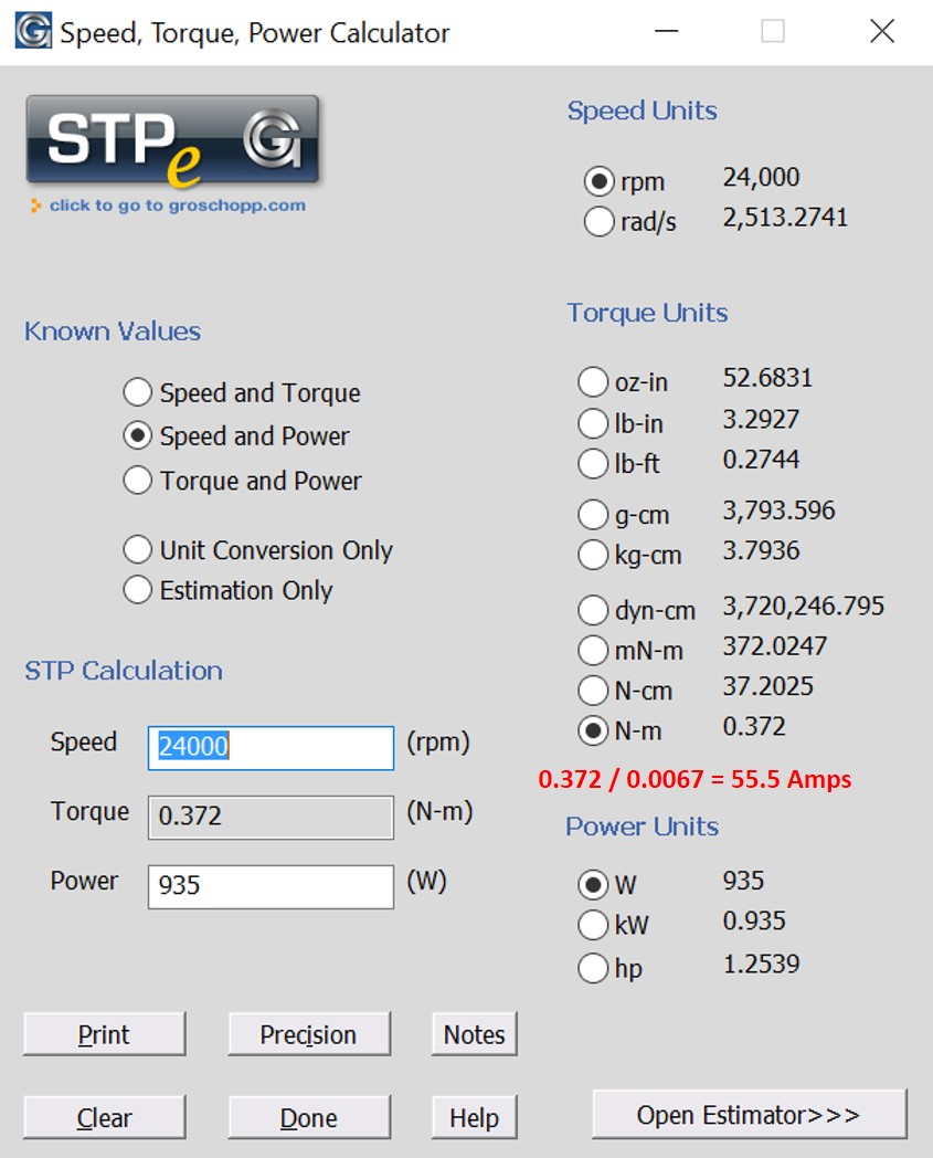
The added “current_motor” (Amps?) * 0.0067 Nm/A = Cutting torque (Nm) and Cutting torque (Nm) / cutter radius (m) = Cutting force (N). “Real Time” display of both in metric and “British” units would be helpful.
A “real time” display of “RPM” would be useful to evaluate the impact of speed changes on cutting torque/force.
“Real time” displays of “temp_mos” (VESC heat sink temperature?), “temp_motor” (what sensor and where will it be located?), “v_in”, and “current_in” would be useful to determine when something is being pushed too hard. (Metric and British units.)
“Real time” displays of “***.hours” would only be useful if a battery is used (may not be a bad idea for current levels required - can the VESC “charge” the battery when the motor is running?)
“tachometer” and “tachometer_abs” only apply if a tachometer is connected to the VESC , right?
“fault_code” could be used to “Pause” the machine, hopefully before damaging or screwing up the project.
The difference in “amp_hours” and “watt_hours” before and after cutter changes could show how much cutter wear and tear occurred.
Cumulative “amp_hours” and “watt_hours” for spindle and machine could show how much wear and tear occurred on those items.
Right now the Arduino is not going to have a display. It will have a fault pin that will go low if there is a fault allowing for E-Stop. Monitoring will need to be done by something on the PC via the CSV output the Arduino will spit out over the serial port.
Also all data will be in metric. Sorry not doing silly conversions on a borderline underpowered microcontroller so Burma, Liberia, and the US can pretend that “Freedom Units” are relevant in the 21st century. Feel free to make the conversions on the PC.
Hey! Those Freedom Units are the Queen and the Royal Society’s units I’ll have you know!
We’ve been discussing how to retrieve the electrical data and use that to make some estimate of the cutter mechanical power for a while now, that’s what I’m getting the power meters and ModBus nasties for my HuanYang VFD to do.
I plan, if I can get that data out, to knock up some little C++ to estimate the mech power based on the spindle amps, RPM etc. for the VFD spindles and it should be easy enough to translate to the BLDC, they are simpler and I’d do that if I didn’t have an ER20 spindle here already.
I’ve also been thinking that much of this data is only really useful in the context of knowing which bit, what size etc. is currently being run which is something we’d only know at the CNCjs level so maybe what we need to do is a plugin for CNCjs and post the spindle data back to that?