Nope, there is a very old and outdated one from the old Sparkfun edition, other than that it is not public (but one can always contact support with a specific question, and they may help)
To be of any value it would need to be calculated over a reasonable time span to provide the user with feedback on how fast the battery will be discharged under current operating conditions. My guess is seconds to tens of seconds. But you should be able to get a pretty good idea when you do your testing. Maybe record videos of the cutting and real time VESC monitoring?
No - torque is proportional motor amperage.
Where did you get this information about hall sensor usage?
I understand the unwillingness to provide the schematic, but I don’t understand the lack of availability of interface descriptions and specifications for it.
In the VESC-tool help options.
If you write in to support@carbide3d.com and let us know your board revision we’ll send out annotated board diagrams on request.
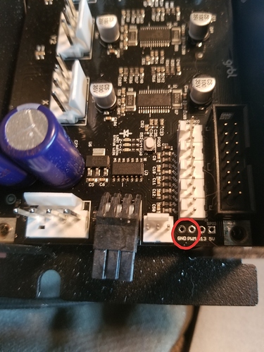
Just watched https://www.youtube.com/watch?v=HPsC1NDrViU and saw that the new boards have that 6pin header for the BitRunner which is where I assume we will need to interface to get the PWM output for the spindle. What are the technical specs of that header? At first I thought it might be a 6pin PCI-E power wire, but the notches do not look correct.
@neilferreri’s guess as to what the connector reference is in that thread, and I documented the pinout here (c.f. #20)
This video provides details on sensorless (and Hall sensor) BLDC commutation - it turns out that sensorless is a lot easier, faster, and accurate than I thought. But it also sounds like it would be wise to hook up the hall sensors anyway.
It, and this other video might help you determine how to properly hook up the Hall sensors if needed.
Here’s some links to some other worthwhile Maxon info and videos. The internet is a wonderful thing!
Apparently “Proper hall sensor support for BLDC” is still on the software TODO list.
Fully automated as in g code controlled on/off + rpm.
The realtime current also seems to update pretty fast. I’ll take some videos in duty cycle mode and speed control mode to show the response.
Fully automated as in g code controlled on/off + rpm.
@LiamN I guess I was wrong about what he meant about fully automated.
OK, now I see the value of automatic on/off. Does (or will) Carbide Motion provide a user friendly speed control (in the GUI) too?
The realtime current also seems to update pretty fast. I’ll take some videos in duty cycle mode and speed control mode to show the response.
Awesome! If you turn on data logging, Excel can be used for analysis.
I was just told this:
“Unfortunately, according to company policy, we are aren’t allowed to share control board diagrams.”
–Jenny (sales@carbide3d.com).
Send it to my attention and we’ll get this puzzled out.
If you dont have the connector it’s also easy enough to solder a couple pins here. Sorry for the potato photo
New tool for Shapeoko?
I can’t believe you posted that without specifying the feed rate, inches per tooth, power and MRR ![]()
Is a chisel technically a single flute tool?
Yup! And look at the size of those chips! 
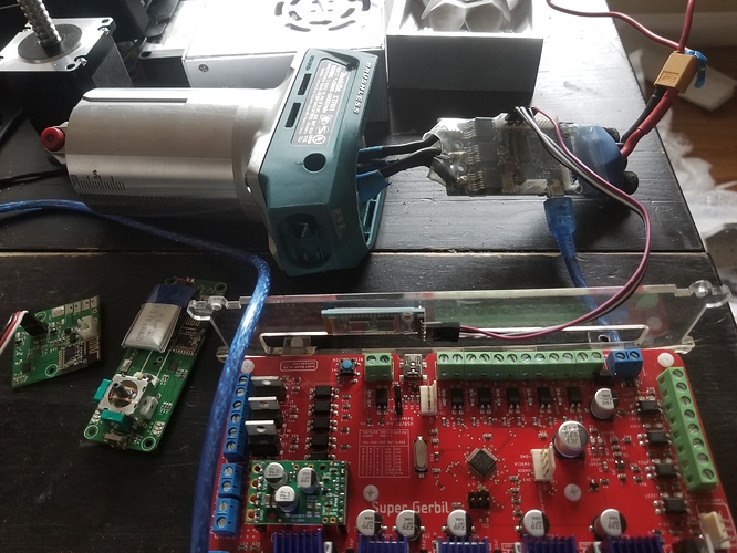
So I tried to connect my SuperGerbil controller HC-05 bluetooth module to the vesc UART to see if was possible to use the android app to log realtime data while overlaying it on a video. Turns out might need a different module.
Good news it that I figured out how to save data logs in .CSV files pretty reliability.
Also looks like @CthulhuLabs got his machine so chips should be flying soon.
Good news it that I figured out how to save data logs in .CSV files pretty reliability.
Could you please post some?
Also looks like @CthulhuLabs got his machine so chips should be flying soon.
Don’t wait on me. LOL. Put that thing in your Shapeoko. You can set the RPM over the USB for now. Get us some data man.


