I stand corrected, “The current drawn from the mains supply by this rectifier circuit occurs in short pulses around the AC voltage peaks. These pulses have significant high frequency energy which reduces the power factor”. So, RMS current measurements likely aren’t much/any easier on the input than on the output.
That hasn’t been my experience testing the draw of digital supplies connected 120V AC. What my clamp-on meters show, has closely approximated the manufacturer’s specification for the device I’m testing.
But there is really little point in discussing, when stripping some insulation of a cord is all that is required to find out.
2 Likes
Your 22V 5 Ahr LiPo battery should be ok if it doesn’t break the drive electronics. If it’s open circuit freshly charged voltage is much higher than that you might want to discharge it a little to reduce the voltage. You could also pick up 3 cheap 6 Volt lead acid batteries and connect them in series.
Battery discharge tests with a variety of power resistor values would allow you to “calibrate” the battery energy capacity (Ahr) for differing power draws.
2 Likes
Huh - I don’t understand!
[quote=“cgallery, post:102, topic:10658, full:true”]
That hasn’t been my experience testing the draw of digital supplies connected 120V AC. What my clamp-on meters show, has closely approximated the manufacturer’s specification for the device I’m testing.
But there is really little point in discussing, when stripping some insulation of a cord is all that is required to find out. [/quote]
The clamp-on meters need to clamp to hot or neutral, one or the other, not both. This typically requires removing some outer insulation on a three-conductor (hot, neutral, ground) cord.
Well if Vince has one, great.
Otherwise stripping some insulation off a three-conductor cord works, too.
Or pulling the receptacle from the wall and measuring on the wire there.
1 Like
I scares me when you refer to the outer jacket of a power cord as “insulation”. Someone could get hurt! The wire insulation needs to stay intact.
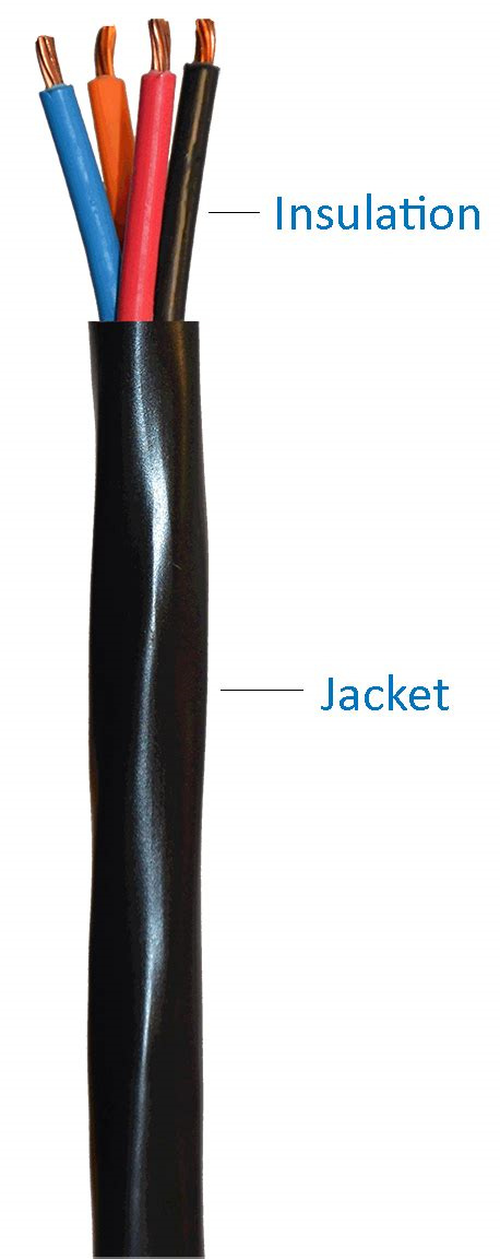
You think saying “jacket” instead of “insulation” is going to save lives? Technically, the jacket is a specific type of insulation.
I’m assuming a minimum level of expertise here, these guys are opening routers, rewiring them to switching power supplies, etc.
Let’s not head down rabbit holes.
4 Likes
Wait… Where am I if this isn’t the rabbit hole?
1 Like
How and how much the power supply input current waveform deviates from sinusoidal will contribute to the measurement error you’ll get with your proposed approach. You can use a scope and current probe to see that the amount of deviation varies greatly from unit to unit based on design and implementation.
But, correlating power supply AC input current measurements with output DC current measurements with a variety of resistive loads would make your approach more accurate.
Your DMM will handle up to 10A of DC current to 600V, place the selector switch in the 10A position. If you move the black probe to the top left connector indicated by the diagonal line it will run through the meter and will be fused. You can try this and see if it works, you will likely only blow the fuse if the draw is more than 10A. You would break your positive input and run it through the DMM so that it is in series with the load, in this case the router. Depending upon the flow of current it will read - or positive. If your Black lead is connected to the PS + terminal and red lead to the motor + input, it should indicate positive current. If it reads negative, reverse the leads. If the fuse blows, you can replace the fuse and we can go to the next incremental step for measuring current.
A DC shunt is another alternative to measure current on a circuit in excess of your equipment. I can expound upon this later if required.
You can also venture into loggers with multiple channels, but I don’t think we need to go there.
Sorry, I’m not getting into this educational experience any deeper; too many “experts” involved! ![]()
The Hare Hotel. Rarely reached when one ventures down the rabbit hole.
Do these routers have a soft-start? I’ll bet they do, as even the Ryobi brushless vac I have has a soft-start.
But if not, and the fuse blows when you turn the router on, then you might want to bypass the leads of the DMM until the router is up to speed, then remove the bypass.
You could also try a slow blow fuse also. I doubt 10amps would be drawn at startup except under extreme load.
The router’s motor controller draws periodic current bursts rather than a fixed constant draw like a passive load (resistor, etc.) would. So, your approach won’t work.
Sadly I do not have any makita batteries on hand.
@Lewscrew by dc shunt do you mean an Rc filter circuit? I was told that might do the trick.
The power supply shows t6.3 slow blow on the board. It’s hard soldered in but I should make the next one replaceable.
The meter also has a min/max, so it should provide max or peak draw.
For a general baseline indication it should work fine. IMO, sounds like Vince has an adequate power supply and has not had any critical failures. At this point for Vince’s requirement is testing current to validate his power supply is adequate.
The approach depends on how specific and accurate you want to be and how much money and time one wants to invest. Others may be set up better than Vince to do some of the testing recommend in this thread.
Vince,
If you search for DC shunt Resistor for Ammeter this should help point you in the right direction. You would only require a shunt Resistor in series with the motor, then measure the voltage drop across the Resistor and calculate current using ohm’s law.
Using min/max readings on your meter, this should give you an indication of peak current.
Hope this helps