One is fixed with another semi floating - however there was a way to adjust then tension on the ball screws which might have been what this video refers to - not sure, don’t think I have seen it.
1 Like
Status Update
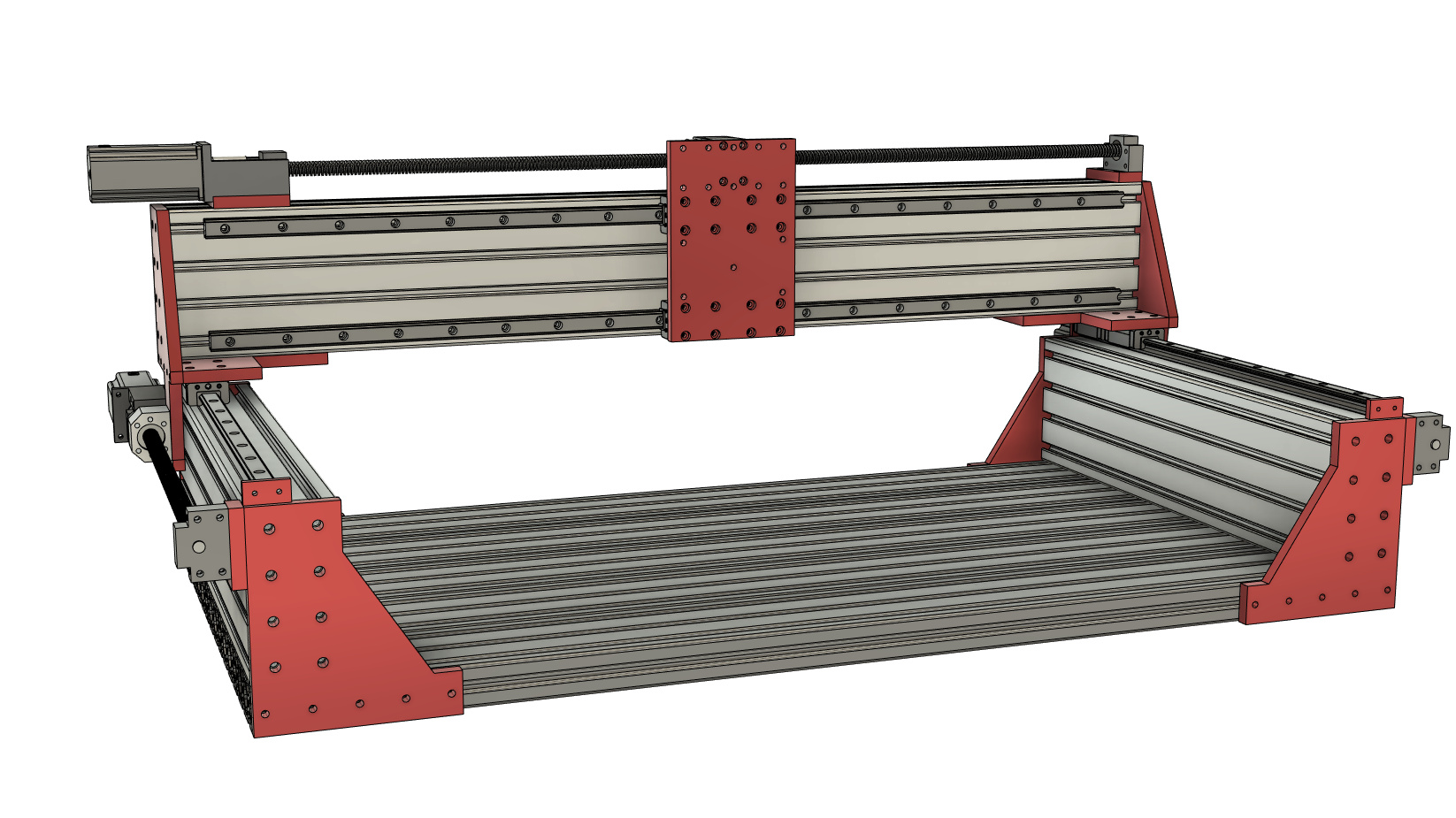
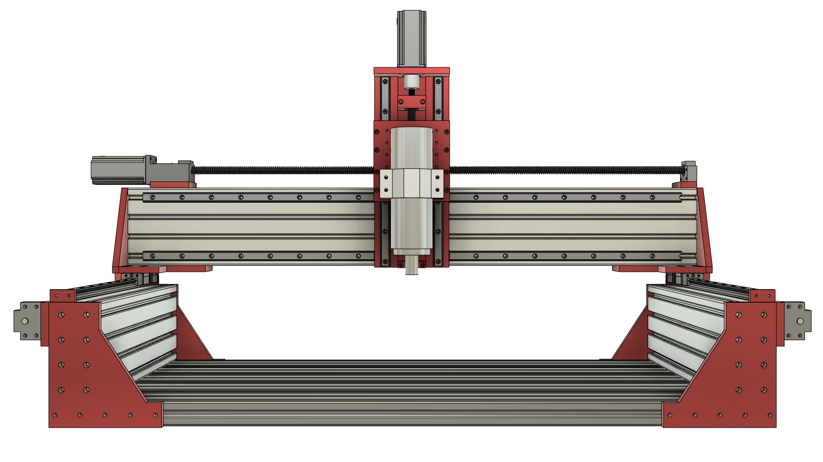
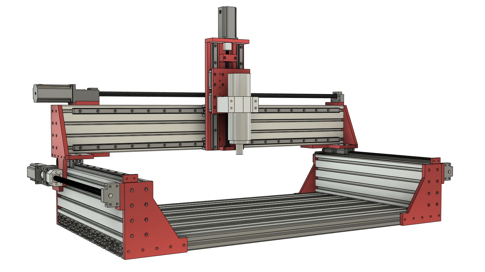
Fusion 360 CAD files are nearly complete. Still have a little work to do on the Z-axis, the cable chain guide supports, and the limit switches. Most materials have been ordered and are on the way. Should be able to start machining end plates within a week. I’ll record some video of the Nomad doing the heavy lifting to share with the community. The good news is that the Z height will be 200.7mm or just a smidge over 7.9".
Also of interest is that Fusion is showing the frame to weigh in at 163kg or 360lbs without the Z-axis and spindle. All that mass should be very helpful to dampen vibrations. This beast is earning it’s “HD” badge.
Here are some pics of the CAD work.
6 Likes
Wow, impressive, it really looks very
sturdy. What are the X&Y dimensions?
It certainly will not move off the table by itself, you will need equipment to move it.
Looks like a really sturdy, simple design - I like it
I do have a few questions:
-
will the plates on the ends of the y beams impact on the work area at all? i.e if you’re tiling on a wide piece of timber will it hit those diagonal sections?
-
how far apart are the bearing pillow blocks on your y axis rails? For the height of the gantry they look fairly close together, which I have been told can reduce rigidity somewhat, you lose a little work area by increasing the distance between them but gain a huge amount of rigidity
Can’t wait to see the build start! I think I have read every single build thread on cnczone.com, and designed my own machines many times but never pulled the trigger and built one
I’d add legs with casters( preferably 80x80 extrusions), some bracing and build an enclosure around it. No more problems with moving around and no need for additional table to put the machine on.
The X&Y dimensions are similar to the Shapoko 3XL because I already have a spot for that size in my shop. Cutting area is 33"x15". I’m also planning a larger unit that will have a cutting area of 48" x 36" and will have larger 20mm ball screws to avoid slap at rapids speed. The unit is designed to be easy to scale up the X&Y dimensions just be ordering longer extrusions, screws, and linear rails.
1 Like
Well, WOW, WOW, 360+ pounds for an XL size machine, I guess you won’t have to worry about someone stealing it in the middle of the night. Yes your honor, I recognize him, he’s the guy with the hernia. LOL
1 Like
Stu, to answer your questions, the plates on the Y beam that overhang onto the X beam stop at the work area. So as long as your work piece isn’t larger than the work area, the you will have the full 200mm clearance. The bed is 150mm (6") wider than the work area, so if your work piece was 200mm tall and 1000mm wide, there would be a clearance problem. Not something I foresee being an issue.
For the bearing block separation, I assume you are referring to the X-axis gantry. They are 120mm apart on center and are 20mm rails. For comparison, Luke’s HDZero had 116mm of separation using 15mm rails. I havn’t heard any complaints from HDZero owners on the rigidity of the X-axis rails. Also, RoboCNC uses the same extrusion profile and rails on a much larger CNC. RoboCNC series
1 Like
Bart, I agree. If I didn’t already have a bench built and sized for the XL, that’s what I’d do. It would be easy to integrate a 80x80 extrusion leg into the design. As for the enclosure, I didn’t have one for my Shapoko, and I’m not planning one for the Zeta as of now. The noise of the Dewalt didn’t bother me and the water cooled 2.2kw should be a lot quieter.
1 Like
This is exactly the kind of info I wish I had when first building my cnc machines. Thanks for posting the link.
Which extrusions are these? Is the gantry a single 40x80mm extrusion? If so, it’ll be interesting how it compares to the HDZero, which uses 2x 40x80 C beams spaced ~55mm apart. The HDZero is almost certainly a lot stiffer on front-to-back loads, but possibly less stiff on up-and-down loads. I’m not a real engineer; I’m not sure exactly how you’d calculate the strength of two beams that are only joined at the ends plus linear rails at the point where the load is applied.
Scott, the gantry extrusion is 80x160mm. It is one of the biggest standard extrusions you can buy. It is significantly stiffer than the 2 C beam rails on the HDZero. I believe the HDZero’s 2 extrusions are 60mm apart giving the outside dimensions of 80x120mm. So my gantry is the same depth and 20mm taller…and it is one solid piece.
Ah, ok. I was guessing that the screw grid on the gantry plates was 20x20mm, not 40x40mm. That’s a hefty extrusion.
Update - Z-axis design complete
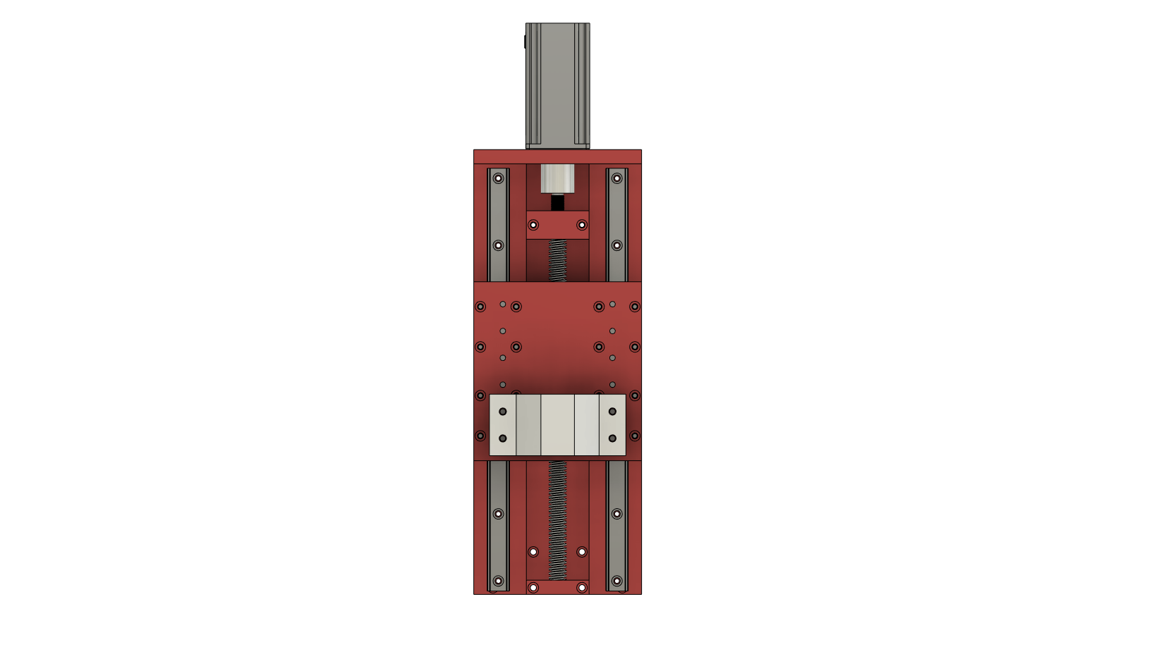
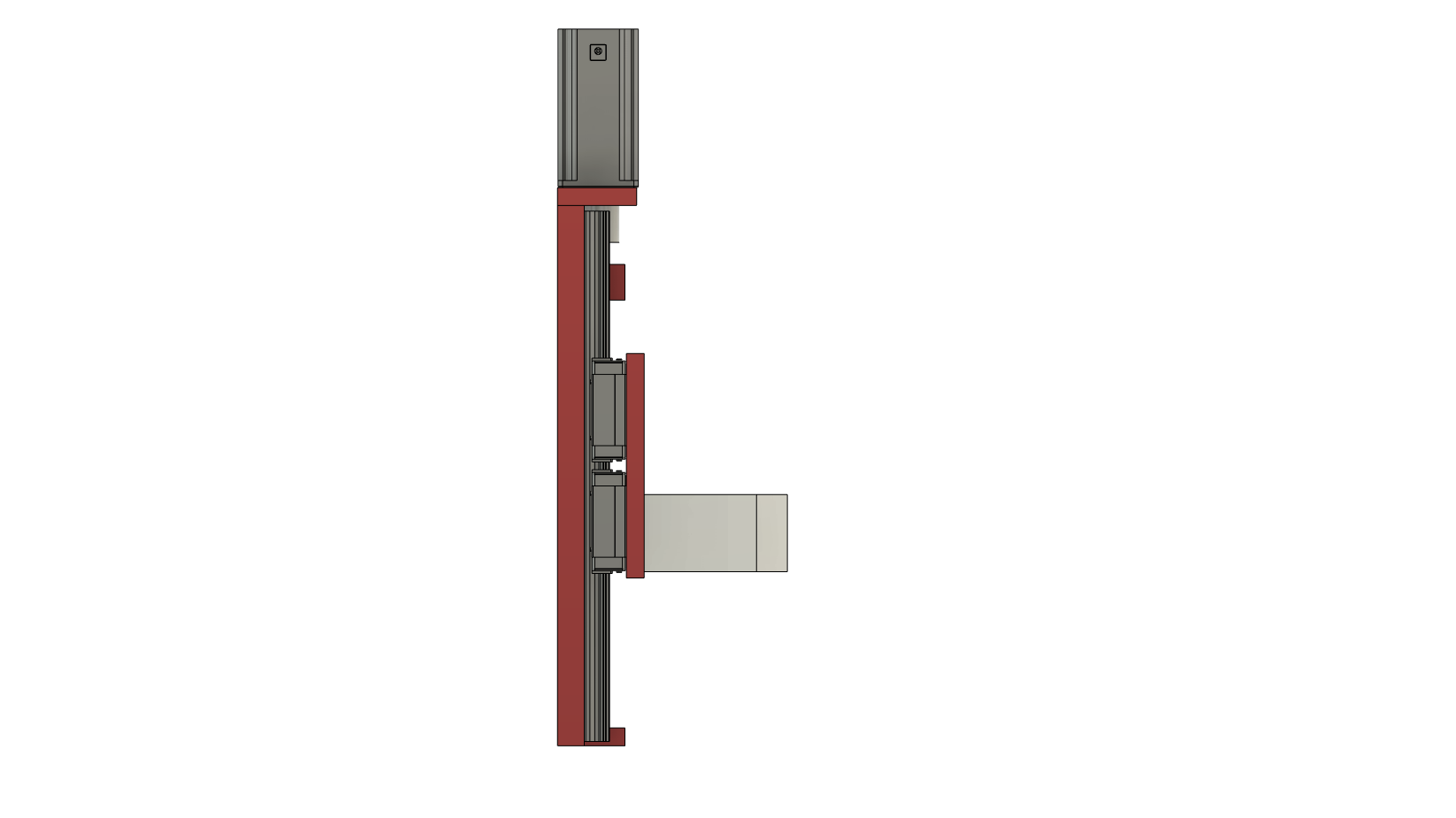
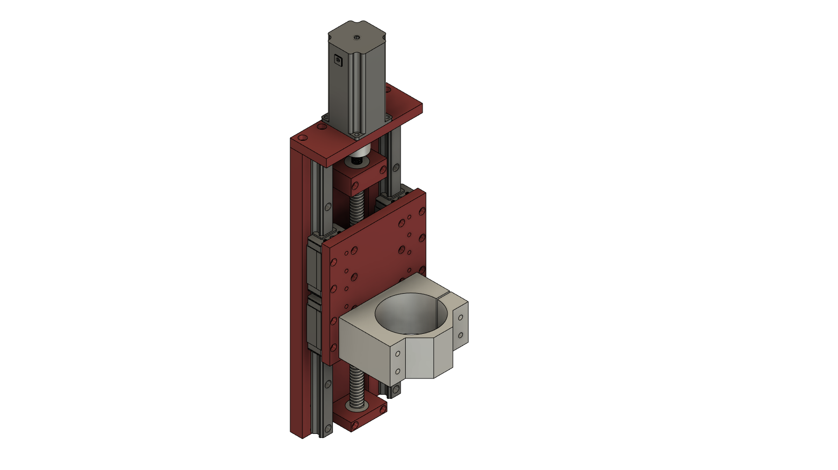
First off let me start by giving mad, mad, mad respect to @Luke for his amazing design on the HDZ. It’s not until you try and design you own Z-axis that you can truly appreciate a someone else’s great design. The Carbide3D HDZ is one of the best designs out there, hands down. One of the toughest tricks is to minimize the depth(stick out) and the width while getting clearance for everything on the z-axis plate (linear rail attachment points to the x-axis, z-axis linear rails, ball screw, slide clearance, and spindle mount). Balance this with keeping good rigidity and getting the travel needed to cover the z cutting area. Not only did Luke accomplish all of this with the HDZ, but he made it look beautiful and refined.
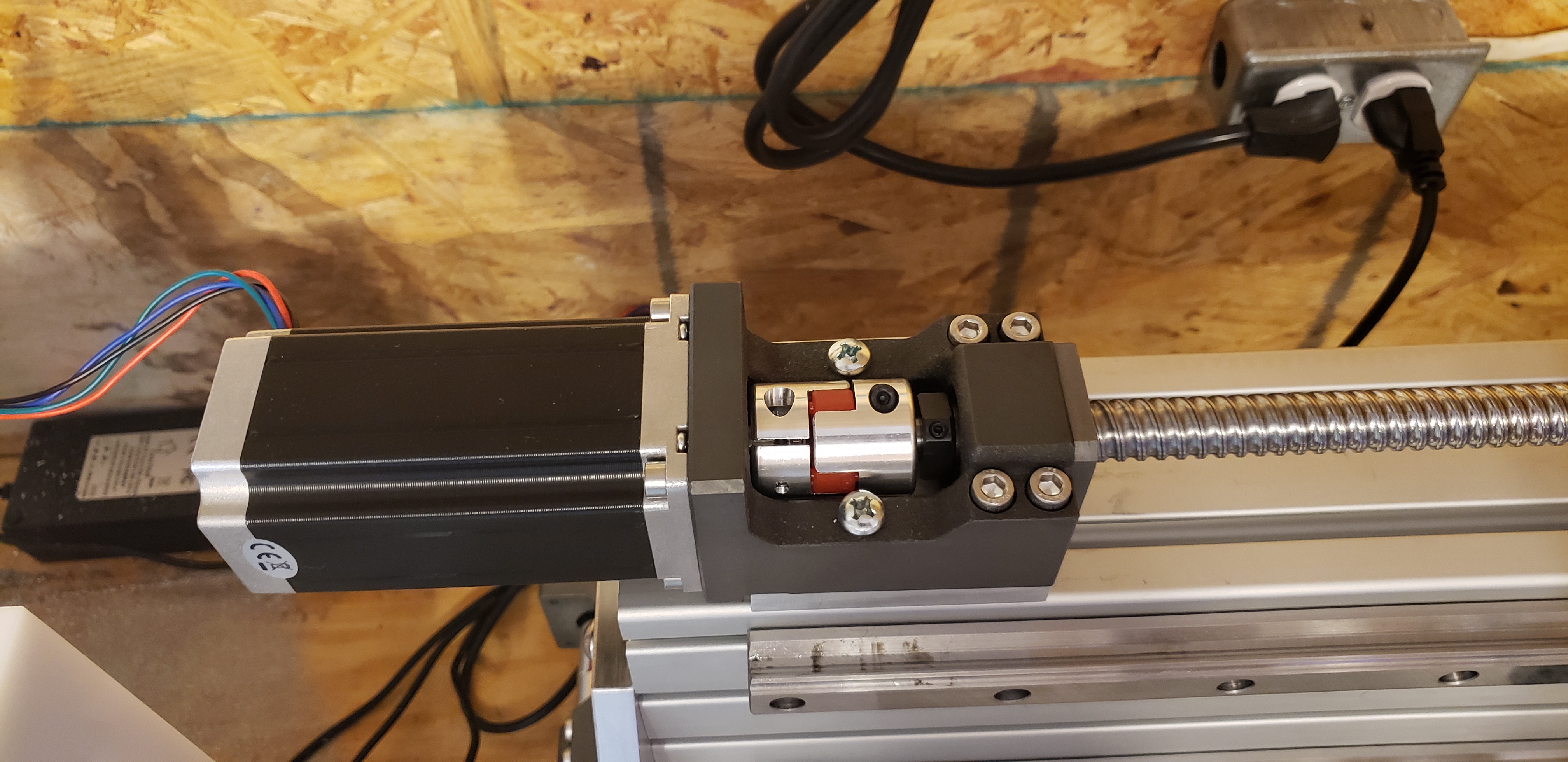
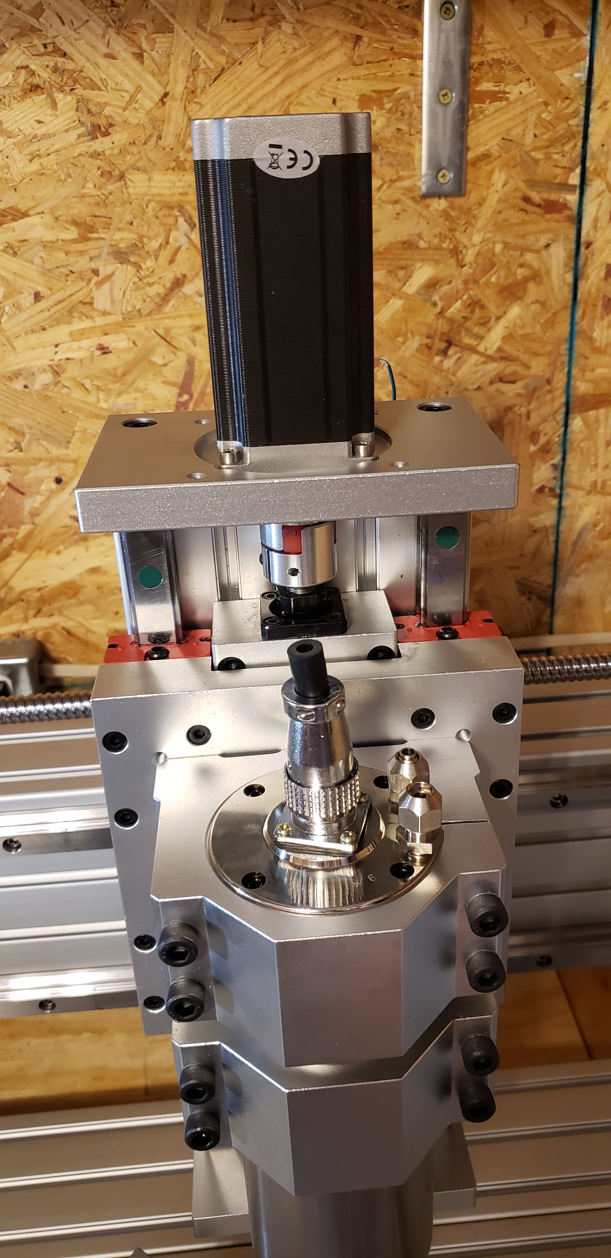
For my Z-axis design, I used 30mm linear rails, 1605 ballscrew, 19mm 6061 backplate, 12.7mm frontpplate, 80mm spindle mount, and a 425 oz.in. NEMA 23 stepper motor. There are dual fixed 6001ZZ bearings on the top ballscrew mount and a single floating 6000ZZ bearing at the bottom. The total travel achieved is 227mm (8.9"). There are 6 sets of mounting holes for the spindle mount creating 5 spindle mounting positions. With the spindle mount in the top location, and the spindle chocked up in the mount to the bottom, its possible to get 20" of clearance between the spindle and the bed. This would allow for side cuts into material up to 18" in width having the material oriented vertically and held with a solid vice.
This design took a lot longer than I expected. I’ve got about 40 hours into just the Z-axis alone. The Z-axis was more complex than the entire rest of the CNC design. I’m proud of the design. It’s not as refined and pretty as Luke’s HDZ, but I’m still very pleased with it. It’s as ridged as I could ever need, and I kept it narrow and shallow. Here are some pics of the design:
Comments and feedback are welcomed and appreciated.
8 Likes
Your Z design looks good, the thought you’ve put into it shows, having that adjustability to get the extra clearance is a nice feature too. It’s a tough balance between having enough clearance for those big jobs and maintaining rigidity for the heavier aluminium jobs
Agreed, I was so impressed when I saw the HDZ design, I’ve also attempted designing a few Z-axis and @Luke has a design that is so compact, simple and effective. It’s quite hard to fit everything in in such a tidy way
3 Likes
Progress on the new CNC was coming along nicely until my Nomad 883 Pro spindle motor driver board decided to die on me. Hopefully Carbide 3D will get me a new driver board for the spindle sent out quickly. Sent support an email at noon, got a response 90 minutes later asking asking for the serial number and the age of the Nomad. My 3 1/2 year old nomad apparently wasn’t hot on their list, so I haven’t heard back from them. Looking at options for an external motor driver so I can keep progress moving. @Jorge hook a fellow Nomad user up with some speedy support. 
Scott,
Have you looked up Masso? I’ve been running my Beaver Pro with Masso v3 for about 2 months. It’s incredibly stable and easy to set up. Works with carbides bitsetter too.
1 Like
Yes. I have the Masso up and running Masso running. It is fantastic. Excellent customer service too.
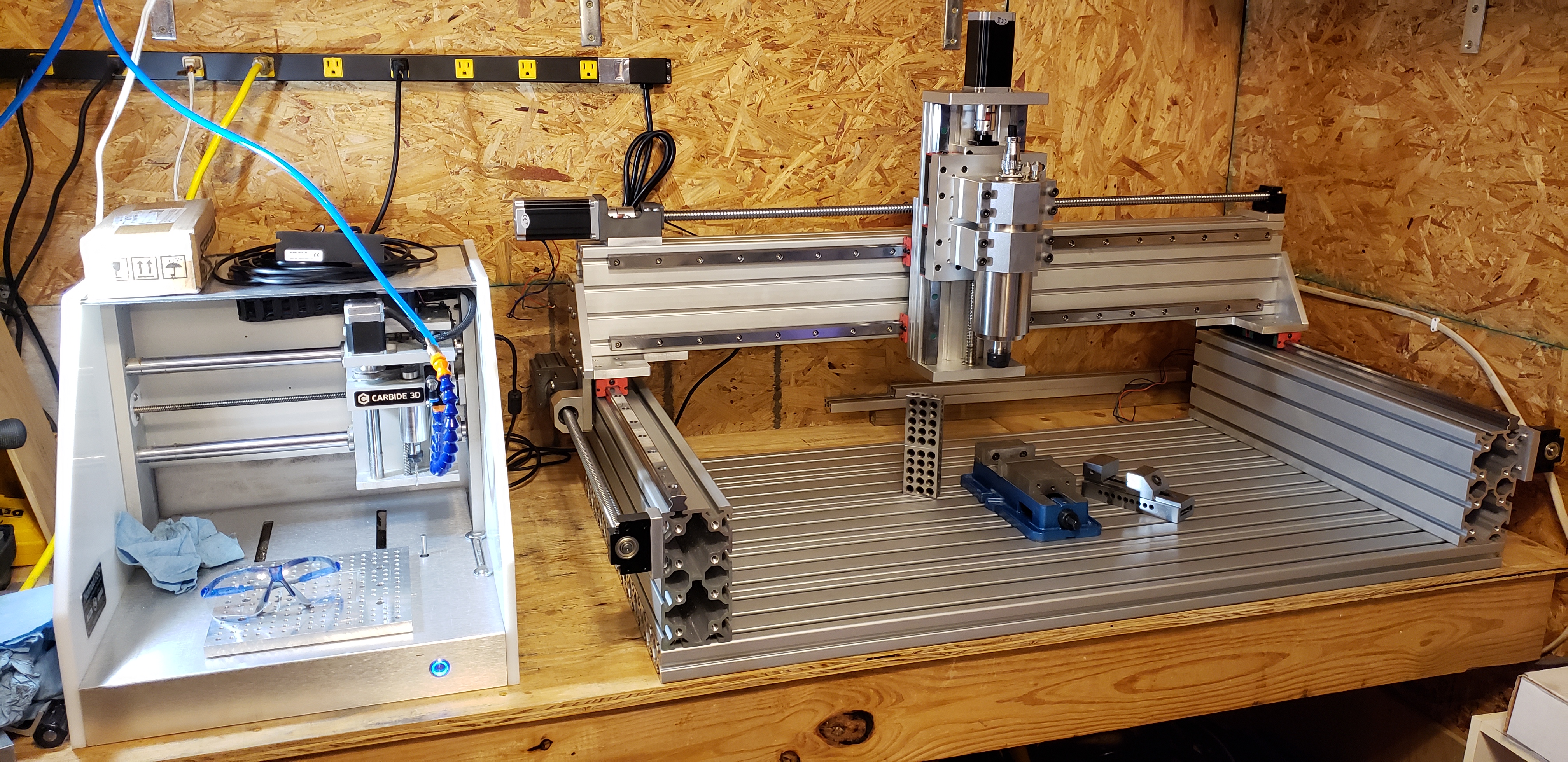
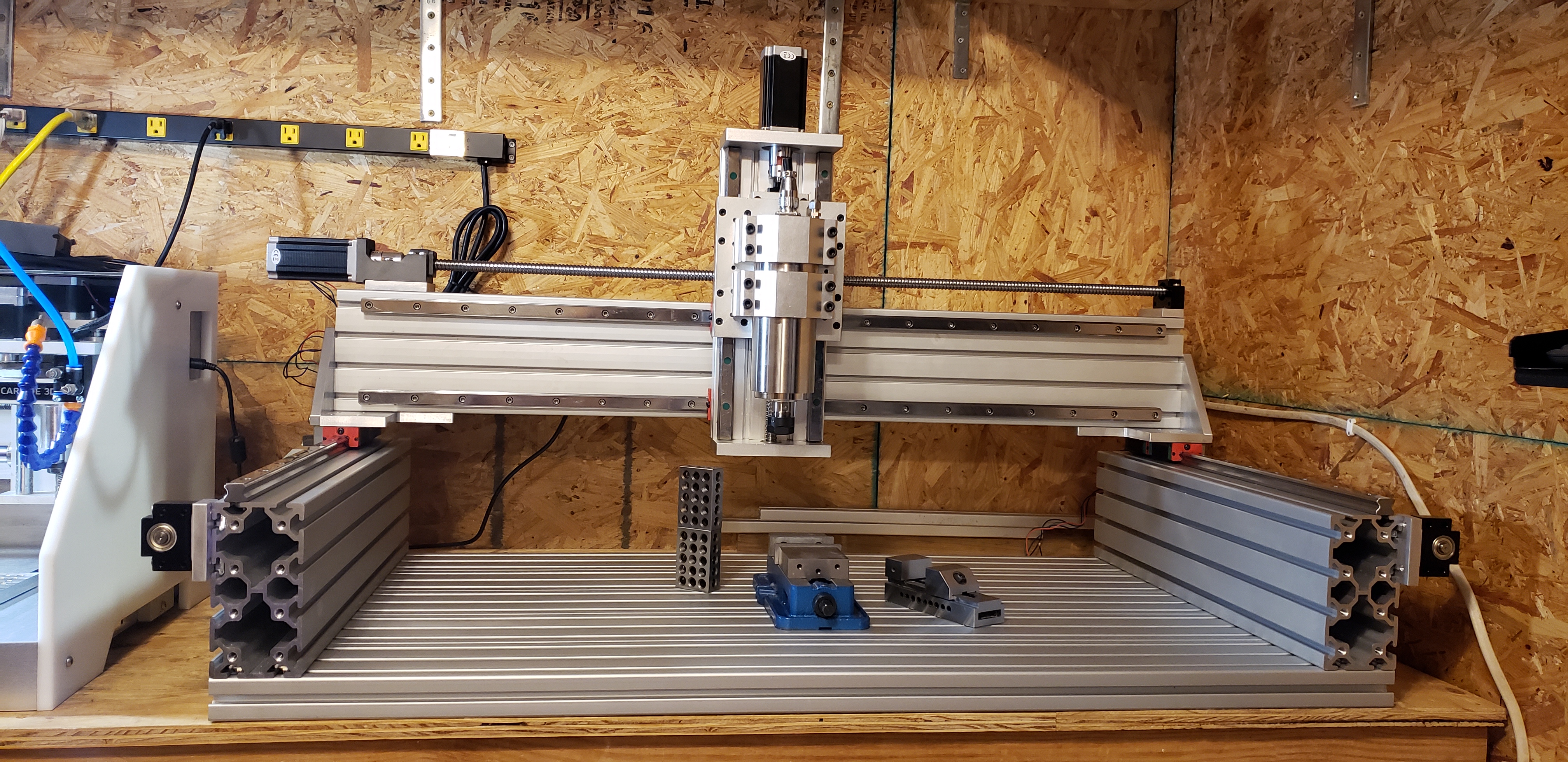
Well, I’m not going to make my goal of having the ZetaCNC up and running by 30 days, but I am making good progress. It didn’t help that the Nomad was down for 5 days, but it’s back up and running great and making chips. To see all the updates and build progress, follow along on Instagram.
Major Update!!!
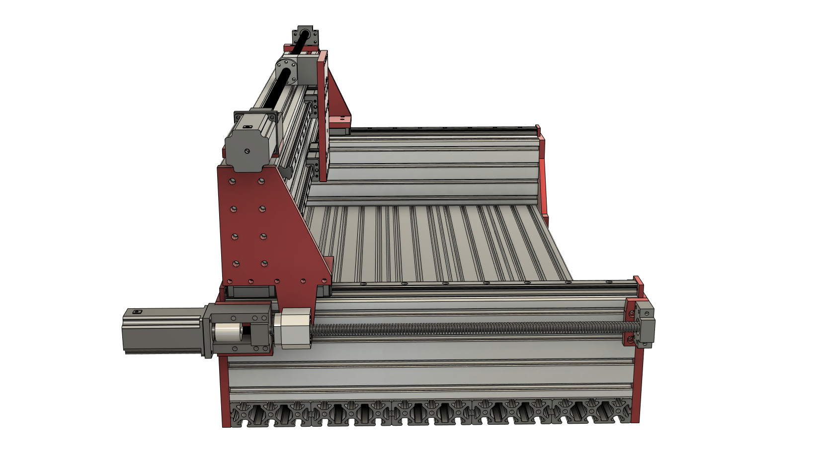
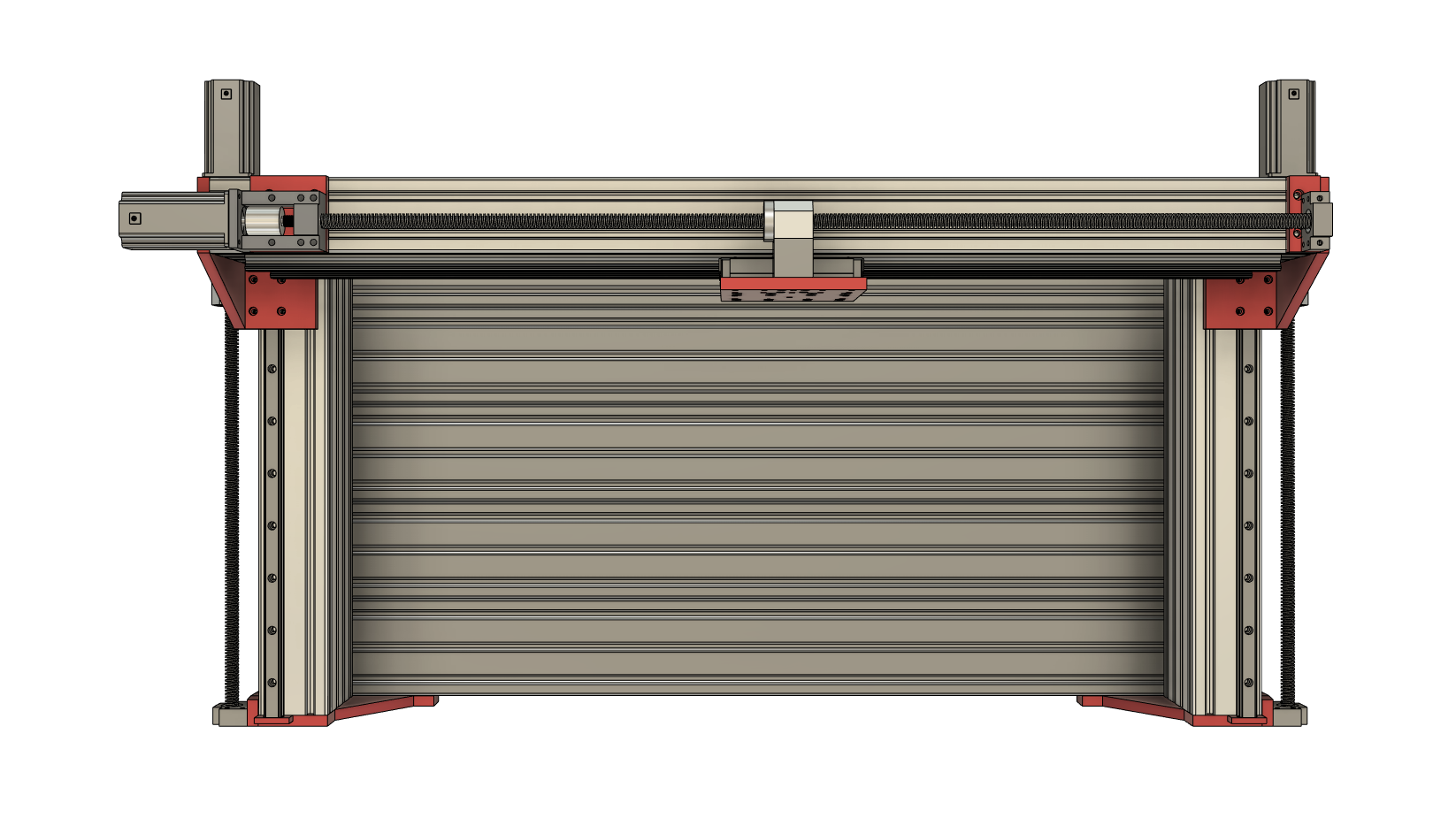
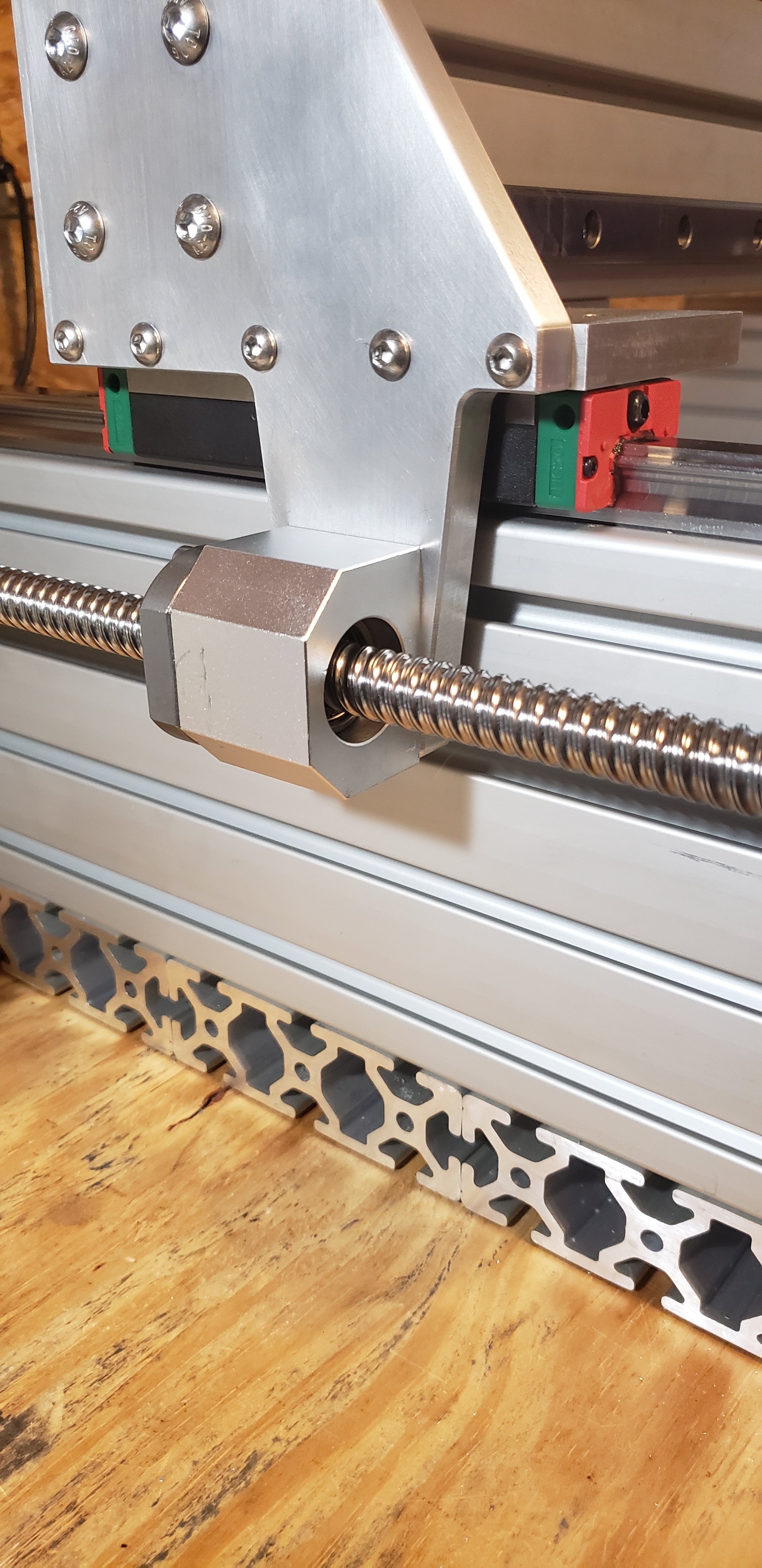
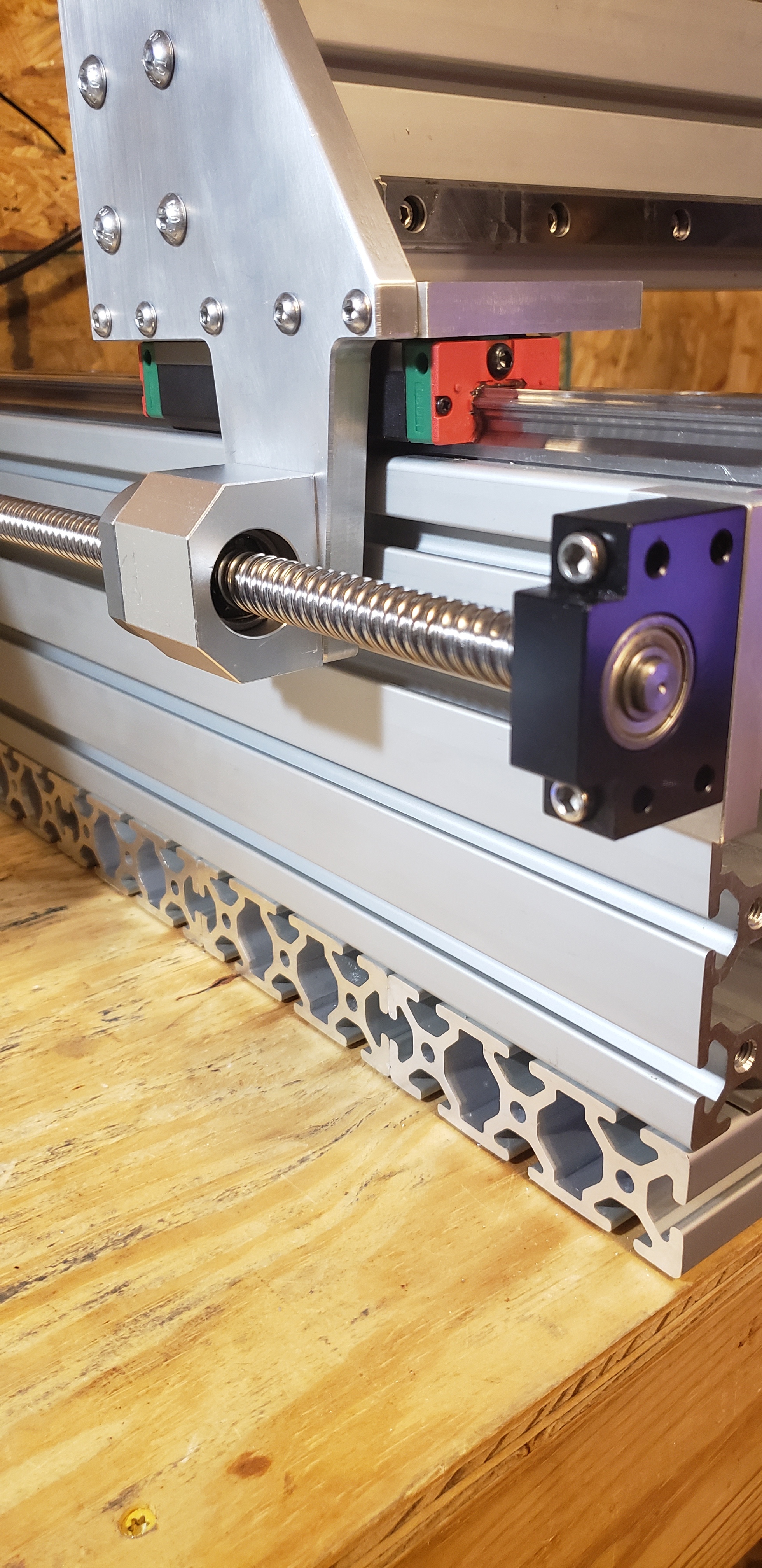
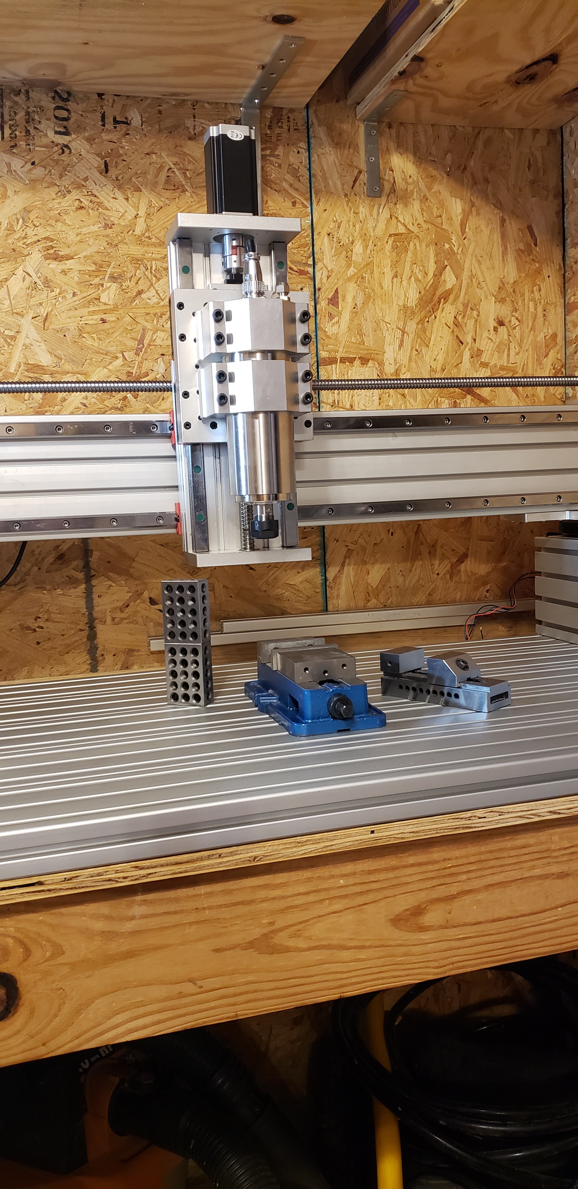
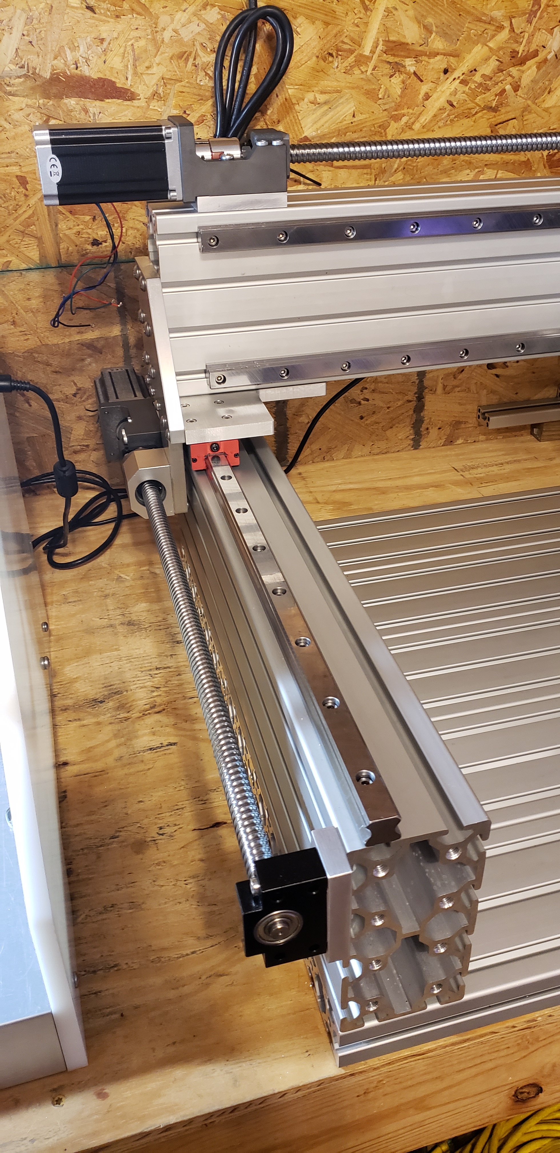
Phase one of the hardware is complete. Tomorrow I start on the electronics and controls. Hopefully I will be at a point of making first test cuts this weekend. X and Y axis’ have been squared and aligned. X-axis is +/- 0.0005" and Y-axis is +/- 0.002". I’m not happy with Y axis precision, but I’ll go back and fine tune it after I get the electronics complete and get through initial cuts. The z-axis is a temporary unit that will be used to build the final production z-axis unit. I couldn’t build that z-axis on the Nomad as it is just way to large to make fit and I want the precision of a single setup and not a tiled job. Other items I will be making on the Zeta are the Y-rail end cap/braces that tie into the extrusion bed. Those are also too big for the Nomad, and quite frankly, they are not that critical as the Zeta is already super rigid without them. I put my entire weight on the x-axis pushing left to right and couldn’t budge the top y-axis linear rail more than 0.00025". Each Y-rail has 40 M6 bolts in it securing it to the bed.
For size reference, those are a pair of 1x2x3 blocks stacked on each other under the z-axis and you can see there is plenty of clearance above the 6". I’ll gain another 1.25" of clearance when the production z-axis is complete.
Follow along on Instagram for daily updates https://www.instagram.com/zetacnc/

16 Likes