Wow, that looks amazing. You have done a great job in both design and excution. Long live the mighty nomad!
Great, now I want to see the stuff you will be making with that Shapeoko HDZeta… an HDMeta with a larger milling area? 
Super slick design! I’ve been following along with your post, glad everything worked out!
Well, it’s been a few weeks since the last update. Here is a run down of the latest status:
- Machine controls are fully wired up and tested
- LinuxCNC is installed, configured, and tested
- Mesa 7i76e control board fully wired, configured, and tested
- Machine homing is complete
- 2.2kw spindle is integrated with LinuxCNC for full spindle control
- 4 gallon water cooling tank installed for spindle
- 8 external relays tied into LinuxCNC control
- Pneumatic solenoid integrated with LinuxCNC to activate air/mist coolant through software
- Machine seems to be happy with rapids at 6,000mm/min (240 IPM) with 0.00625mm (0.000225") resolution on X and Y axis and 0.003125mm (0.0001125") resolution on Z axis
- Homing switches on both y-axis that work in unison to align and square the gantry…this feature of LinuxCNC is bad ass (works a lot better that the manual squaring many of us had to do on our Shapoko machines)
I could give up a little resolution and gain some speed to challenge @Luke and is 12,000mm/m CNC, but for now, I happy with the rapid speeds and would prefer to keep the increased resolution.
Soon I will be testing repeatibility and then making first cuts. I have checked the spindle for tram with a machinist square and it is pretty darn close. For now, I’m calling tramming good and will address it later if it needs it.
And on a final note, I used the Nomad 883 Pro to build the ZetaCNC, and soon I will be using the ZetaCNC to do some serious upgrades to the Nomad 883 Pro. Gonna give it enough power to make @wmoy and @Luke fans of the Nomad.
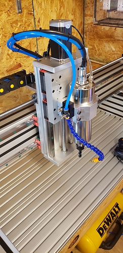
Here’s a pic of the wired up Z-axis and spindle.
Some Instagram posts showing the 3 axis’ homing
Cheers
Very cool @Design_Make_Test this machine is looking epic! Are you considering going commercial with this design or is it just for your own use?
What driver board/s are you running under the 7i76e?
I use a mesa 5i25 under LinuxCNC on my shapeoko and hadn’t considered homing on both y-axis to keep the gantry square. Any chance you’d be willing to share you Hal and ini files so I can see how you set it up?
Stu, thanks for the great feedback. I am investigating the feasibility of making this a commercial offering and trying to get a read on the market demand for the segment above the hobbyist machines and the industrial machines.
The stepper drivers I am running are the DM860T’s from StepperOnline. They are designed for NEMA 34 motors, but I wanted to have plenty of headroom to drive the 425 oz.in. NEMA 23’s.
As for getting the tandem Y axis homing working, you need to make sure you are running LinuxCNC 2.8 or 2.9 to take advantage of this feature. Earlier versions did not include that capability. The other t key components are having a homing switch on both Y-axis and using separate Step generators for each Y-axis on the Mesa board. Almost like it is a 4 axis machine. That’s where things get tricky, when setting up Joint (as LinuxCNC defines them) in the PNCConf tool, you can NOT test the Y-axis unless you remove the steppers from your machine. If you don’t remove the steppers, you will rack your gantry. So my suggestion is to remove them and make sure they are both spinning in the correct rotation for positive/negative Y-axis movement. Once you have that worked out, reassemble and launch LinuxCNC and run the homing sequence. You won’t be able to jog until you home.
If you want the .hal and .ini files, send me a PM with an email address. I’d prefer not to post them as they are somewhat unique to each machine design and they could cause major damage to someone’s machine if they just loaded them and ran them.
I use Mach4, which has the independent homing of slave motors as well. I actually dismissed the [BeaverCNC] proximity sensors for use of this feature, as I got lots of bouncing on the signal (when the metal is just at the right position it causes the sensor to flap on and off) and the mounts are not ideal for fine adjustment on the SO3.
Dan,
I suspect the switch flapping was triggered by not having a good target to sense consistently. I did a bunch of testing with these before I finalized the design on the Zeta. Having a large steel surface exactly parallel to the face of the sensor is key to repeat performance. While the sensor will detect any type of metal (including aluminum) in any size and orientation, the repeat-ability will not be good. I used a 1" angle iron that is 1/8" thick for the z-axis and 1.5"x1/8" flat bar for the x and y axis’. This gave good repeatable results with no false triggers. There could also be a software issue if the logic does not back the axis up far enough to properly clear the trigger. But my guess is it’s the sensor target as I have not seen many machines that put much thought into this aspect.
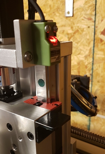
Here is a close up pick of my Z-axis sensor and sensor target (black angle iron). I have homed the machine over 100 times in the last few days doing testing, and there has not been a single issue yet.
Thanks for the insight. I still use a proximity sensor on the Z (with the HDZ), I don’t see issue with homing, however I have noticed degraded repeatability, however it doesn’t matter much at this time as I re-zero Z during setups. I’m sure my homing routine could use some fine tuning too.
New Instagram post showing the ZetaCNC making some upgrade parts for the Nomad. Look for a Nomad Upgrade post coming soon. The amount of aluminum you can hog out on a rigid machine is simply insane.
@Design_Make_Test Any good suggestions on a source for 1610 or 2020 ballscrews? I am looking to upgrade my 1500x1500mm machine from belts to ballscrews. With Nema 24 380oz can I direct drive 1500mm ballscrews? I would like to keep my rapids around 200-300ipm, no need to push those any higher for what I do. I already upgraded by machine to all 15mm linear rails and now I am realizing the belts are the weak link.
@Winters636 My ballscrews came from Aliexpress. You can have them custom made to length or buy one of the many pre-made lengths. If you go the custom route, plan on 2 or 3 weeks of going back and forth with their technical team to get the dimensions correct. Make sure they provide final drawings that you review for correctness before ordering. Next off, trying to integrate ballscrews into a machine has a number of challenges that you don’t have with belts. For starters, tolerances have to be dead on. Even a few thousands off alignment at either end support or the ballscrew attachment can add unnecessary stress and strain to the screw itself. You don’t want the screw itself to be flexed any. Having slotted mounts in 3 dimensions solves this, but isn’t easy to do. My machine has slotted mounts in 2 dimensions and the 3rd dimension is shimmed to tolerance as necessary. The shims I used ranged from 0.02mm to 0.13mm depending on the axis. One way to check this is ballscrew can easily and smoothly be turned by hand the full distance of travel. If there is any binding, you will have to make adjustments.
Assuming that didn’t scare you off (and it shouldn’t) the next thing to consider is speed vs resolution and what you will use as a controller. The controller and the stepper drivers dictate how fast step and direction pulses can be generated. In my case I am using LinuxCNC connected to a Mesa 7i76e controller. There are tons of forum posts on LinuxCNC about how to set that up to maximize step pulses. From there, you have to make sure you stepper drivers have are connected to a properly sized dc power supply. In my case, I am using a 13.5 amp 72 VDC meanwell power supply. In order to determine the supply voltage you need, use you NEMA motor specs and plug them into a tool like https://www.daycounter.com/Calculators/Stepper-Motor-Calculator.phtml. You will need to figure in your micro stepping factor. Micro stepping is where you have to make some trade offs. You want some form of micro-stepping to smooth out the motion, but the more you have, the slower that motor turns.
Lets look at an example, if you were using 1610 ballscrews they will be 16mm in diameter and will travel 10mm per full revolution. Most stepper motors have 200 steps per revolution. 200ipm is roughly 5,000 mm/m. Since the ballscrew travels 10mm with each revolution, it would need to turn 500 rpm to achieve this speed. in stepper motor pulses, that equates to 500x200 = 100,000ppm. The resolution of the axis would be 10mm/200steps = 0.05mm (0.002"). Not that great for a CNC. The same example with 1/8 micro-steps implemented would push the resolution up to 0.00625mm (0.00025") which is a lot better. But, it the pulses remained at 1000,000ppm, then the speed would fall to 625mm/m (25ipm). In order to keep that same speed, the controller would need to increase to 800,000ppm and the power supply would need to be adjusted accordingly.
It’s a lot to process, and I’m just giving you the high level considerations. I spent several weeks researching the each aspect of the of the system and made a number of redesigns to optimize my final design. Currently I am running at 6,000mm/m with 1/8 micro-stepping and the machine seem very happy with that. I haven’t lost steps at any point which to me is more important than going faster. I suspect I could push it to 12,000mm/m without any issues, above that, and I would have to worry about whip on the x axis. Speaking of whip, for 1.5m axis length, you most definitely want to go with 2010 ballscrews or larger.
Sorry that got so long winded, but there is a lot to consider with ballscrews. Don’t let that discourage you, just make sure and do your homework before you pull the trigger.
This topic was automatically closed 30 days after the last reply. New replies are no longer allowed.

