Looking for feedback on my usage of F360. I have a parametrized template for a sign with parameters for dimensions of the ‘stock’ and the dimensions of the ‘sign’ cut from the stock. About the only thing I have to go in and change to produce a custom sign is the font, size of text, and depth of engraving.
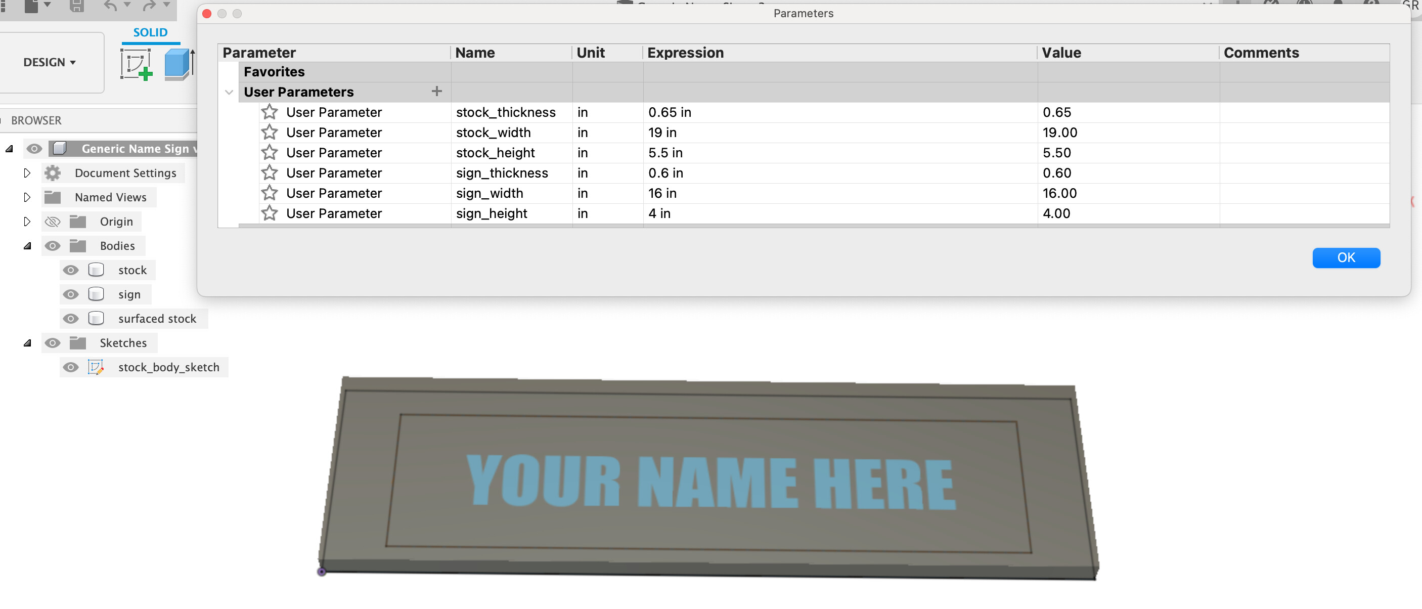
Graphic 1 shows my parameters and my 3 bodies generated by those parameters:‘stock’, ‘sign’, and ‘surfaced stock’.
Given I want to zero everything after the surfacing work from the top of what remains, I found it made sense to use 2 setups. One with a zero top left of the original stock, one with zero top left of the surfaced stock.
For the surfacing setup I use the ‘stock’ body as the stock and the ‘sign’ body as the model. I need to tweak my feeds and speeds here a bit, but I am generally happy with that operation. The only thing I feel like I need to fix there is to add some tangential extension (or something) as there always seems to be a small patch of unsurfaced area left at the top outside the boundary of the sign. It doesn’t hurt anything except to get in the way of my sander a bit.
For the primary setup I use ‘surfaced stock’ as the stock and the ‘sign’ body as the model. It has operations:
rough contour: bulk contour material removal that doesn’t cut all the way through an leaves enough for everything to be secure. I could do this later but I feel like doing this bulk removal now makes the following chamfering operations easier on the machine as a bulk of material has been removed.
chamfer operations (3): Progressively deeper chamfer operations as to control aggressiveness of cut. I originally had just one at full depth and that felt way too aggressive for the Peoko. Split the work among 3…still feels a bit aggressive…Is there a different toolpath I should be using or better way to control how aggressive things get?
letter engraving: Engrave operation to whatever depth looks right given the target text. As the sketch that contains the lettering is on the xy plane, I use model top - offset to control depth of cut. Previously had ‘selected contours’ selected…that was aggressive. I do 2 passes as engravings seem to cleanup with a second pass.
finish contour: A contour finish pass that cuts to full depth (with tabs) that is only taking off 20 thousandths until it gets .1" from stock bottom after which it is full slotting. I am unclear as to if this is even needed or if I could just save the rough contour cut above till the end and forgo…or if I could just do this finish contour and forgo the rough contour.
So questions I know to ask:
-
Outside of adding some tangential extension, is the any way to avoid the wee bit of unsurfaced area at the top of the board.
-
Do I need two separate contour cuts or could I just get away with one or the other. I am dealing with wood here that gets a decent sanding before being called done and I am not sure the extra surface finish gained by a finish pass is all that useful.
-
Is there a better way to control the aggressiveness of the chamfer cutting than splitting it up into 3 toolpaths? In the presence of better control, is the bulk removal by the rough contour necessary?
-
Any neat ways to use parameters for cutting, say for depth of the engrave?
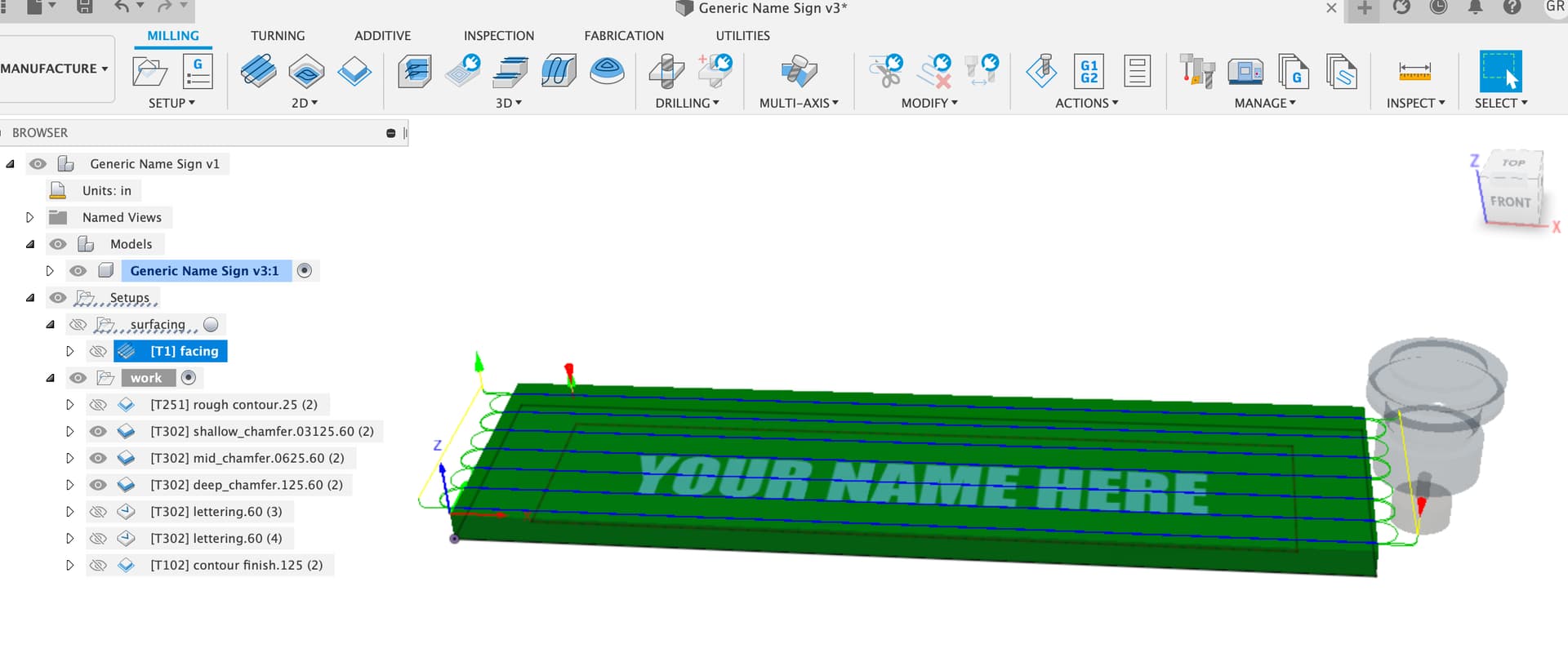
Graphic 2 shows my CAM. Also attached the Fusion file in the chance you would like to get a good look at the details of things and give me pointers/suggestions that I didn’t know to ask.
Generic Name Sign v13.f3d.zip (215.9 KB)