I know I should be able to fool it into doing an outline but is there a way to have it do a cross hatch infill with a drag bit?
Well… mostly. If you do a texture toolpath, you can mostly fill the shape almost uniformly and at an angle of your choosing, and doing that twice can get you more or less a crosshatch fill. If that’s not good enough, then no.
My Mother’s Day projects went in a different direction, but I’ve got my diamond drag bits and black granite floor tiles at the machine ready to go, so I’m planning to start scratching soon. I’m planning to use LightBurn and a simple G-code bodge to get true crosshatching with full control. More discussion in this thread:
1 Like
The short answer is yes, look at this video. I think John has a few more engraving projects.
4 Likes
In that video, he’s using a pocketing toolpath from the “contour” option, which basically makes concentric infill. You can’t use a pocketing toolpath to do a crosshatch infill, so you’re left with attempting to finagle the “texture” option to get close to a real crosshatch infill.
1 Like
Well, you could use an SVG drawing program to fill the areas as desired — I’m hoping to look into doing that sort of thing with METAPOST (or possibly Tool Path Language https://tplang.org/ ) next year.
I was playing around with Inkscape and doing something along those lines, but the path operations in Inkscape work on closed curves. You can’t just make a collection of lines and do an “intersection”, for example. I was thinking that I could make a “comb” (think a parallel-lines zig-zag path with the first and last nodes connected), then do path operations on that. That would leave the area fill as lines, but it would also leave a “dashed” outline, as the nodes where the “infill” intersects with the outline of the shape would alternate open and closed as viewed from the perspective of following the outline.
Theoretically, I could do some post-processing on the resulting “infill” to statistically determine the mode of the slopes of all the linear segments in the path’s data, then remove all path segments that do not match that slope. (Basically, turn the contents of the d attribute into a collection of “move, line, move, line” subpaths.) I’d have to also consider what to do with the literal edge case of a fill segment being superimposed on an outline segment. (Should the fill segment be dropped so you don’t double-scratch, and if so, what’s the tolerance of “superimposed”? Less than 50% of the line spacing?) With a “comb” generator, a path Intersection operation, and a post-processing extension to remove the extraneous outline segments, I could achieve a complete linear infill. Following that twice, and you’ve got a crosshatch.
If there were a more straightforward “make linewise fill” Inkscape extension, things would be easy on the user side. Unfortunately, I may not grok the math of curves well enough at present to consider that within my current capabilities of being something I could write well. This may change, and I may be able to come up with an acceptable approach that makes it click in my head. For now, it’s trivially easy to do in LightBurn, and converting the resulting G-code from laser to diamond drag bit application is pretty straightforward. I’ll be happy when there’s a nice free and open workflow, but $40 for LightBurn to make life easy seems reasonable, as that’s below the price of a diamond drag bit. Plus, I can probably work up a user-friendly laser/drag-bit converter, since the G-code changes are all but trivial.
Carbide Create “Texture” toolpath info:
I was hoping to be able to do something with just Carbide Create, but the “Texture” toolpath does not get you what you need. I set “Stepover” to my desired line spacing, “Stepover Variation(%)” to zero, “Min Depth” and “Max Depth” both to 1mm, “Min Length” and “Max Length” equal and well over the longest possible line across my design (e.g. 500mm or whatever), “Min Overlap (%)” and “Max Overlap (%)” both to 100, and “Angle” to my desired angle (45 degrees in this case). The resulting G-code looked like this:
G1Z0.000F635.0
G1X280.090Y204.908Z-0.422F1905.0
X275.746Y200.564Z-0.750
X271.398Y196.217Z-0.942
X267.383Y192.201Z-1.000
X263.367Y188.186Z-0.942
X259.019Y183.838Z-0.750
X254.675Y179.494Z-0.422
X250.671Y175.490Z0.000
G0Z12.700
The Z depth was not constant, as I would have expected. With this result, I went back and changed the “Max Depth” to 2mm and exported the G-code again. Looking at the results of that experiment, it is now clear what the “Min Depth” and “Max Depth” values actually are. They’re the range of the maximum depth of each texture segment. Each texture segment’s actual Z depths range from the surface at the ends to a randomly selected maximum depth somewhere between the entered “Min Depth” and “Max Depth” values.
So, “Texture” toolpath option does not yield G-code suitable for diamond drag bit engraving.
Just curious if your drag bit is spring mounted or fixed. Mine is spring loaded and I use VCarve engraving feature. Would the small variation of Z height be absorbed by the spring and make it more or less uniform?
1 Like
Okay, you’ve made me have to do a quick experiment. Being spring-loaded and within the elastic limit of the spring, the force should be linear (Hooke’s Law). So, all I have to do is collect some measurements of the force vs. displacement. I grabbed my digital kitchen scale (who doesn’t measure bulk ingredients by mass?) and headed over to the machine.
Experiment: Force vs. Displacement
mm  | "grams"
0.5 | 272
1.0 | 290
1.5 | 310
2.0 | 335
2.5 | 346
3.0 | 375
3.5 | 382
4.0 | 414
4.5 | 419
5.0 | 451
5.5 | 456
6.0 | 491
6.5 | 495
7.0 | 537
The measurements in millimeters are the displacement of the Z axis, with zero defined as the diamond point in contact with the surface but not exerting any measurable force. (Note: My scale reads in “grams”, but obviously, it means the force equal to the weight of the displayed mass at 1G. Most likely nobody cares, but while I simply can’t use grams as a unit of force, it’s more relatable than actually using Newtons, hence the “grams”.) Charting this out and doing a linear regression, we get the following:
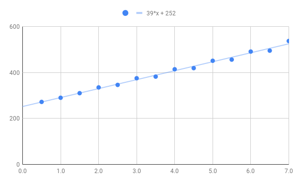
According to the linear regression, the force would be zero at Z = -6.5mm, which is basically a measure of the amount of preload compression on the spring.
Analysis: Confirmation By Measured Dimensions
So, how does that compare to actual dimensions? Well, conveniently, I happen to have purchased extra parts. Here’s an annotated breakout of my diamond drag bit.

- Overall length: 50mm
- Body length: 38mm
- Tip length: 27mm
- Spring length, uncompressed: 25mm
- Set screw length: 5.5mm (including the length of the set screw and the amount it’s inset in the top of the tool)
We can then calculate the spring preload by taking the overall length (tip, spring, and set screw) and subtracting the two ends to get 7.5mm (50mm - 27mm - 5.5mm). The difference between the two values (6.5mm vs. 7.5mm) is likely made up of a combination of experimental error, measurement error, and possibly differences in the actual pieces being measured (since I didn’t disassemble the actual tool I used for the force measurements).
I’m sure if I took more care with the experimental setup and measurements (and took more data all around), the experimental error could be reduced. Regardless, it was more of a sanity check for the useful result, which was determining the approximate preload in the spring and the resulting force-vs-displacement curve. So, what is my answer to your question?
Conclusion
Given the preload on the spring, if you plan your Z-zero to yield about 3mm of tip retraction, a variation in stock of +/-1mm will only result in about a 10% difference in force applied. Therefore, I would be fairly confident that small displacements in the surface of the stock are unlikely to cause noticeable differences in the engraving.
(Note: Obviously, as you pass full extension, the force goes immediately from the preload force to zero, which would be distinctly suboptimal.)
Application to Carbide Create
If you made a “Texture” toolpath with “Max Depth” basically set to a very small value, then only your retract height would be relevant to the Z axis. As long as your retract height was high enough to clear full extension, the slightly wavy actual Z travel wouldn’t be relevant. However, the actual endings of the texture toolpath’s subpaths are not right on the edge of the shape. They don’t quite reach. I’ll have to see whether that turns the segment-exit edges “fuzzy” in practice.
3 Likes
Great analysis but I think you have to take into account that most of the materials you would engrave are hard which further reduces the impact of the force you apply to engrave. Even if I applied one vs 20lb of force on hardened steel, the mark from the engraver would essentially be the same but for soapstone, it could certainly make a difference. All this to say that material hardness could be an issue especially at both end of the scale.
My point was to determine the preload and force-vs-displacement curve to see what range of forces you actually have at your disposal. I am not attempting to state what the proper parameters of any particular project are.
One thing I did not include above is that the minimum compressed length of the spring I found to be approximately 9.5mm (after pinging my spring across the room several times). That means that you have approximately 8mm of travel to work with between the no-load dropoff and bottoming out at maximum force. That, in turn, means that for the tool I measured, you have a finite range with a minimum of about 250 “grams” at full extension and a maximum of about 560 “grams” just before bottoming out.
So, basically, you have more or less a 2:1 ratio of applied force across the usable range of a spring-loaded diamond drag bit such as mine, pictured above. Of course, applied force is only one of the two variables available. The other is cone angle. I would hypothesize that the cone angle’s significance should correlate with the ratios of the horizontal cross sections. The sine of the half-angle (the angle between the side and the central axis) is analogous to the radius, so that squared should be proportional to the area.
 60° -> 0.25
 90° -> 0.50
120° -> 0.75
So, assuming the engraving effect scales with the force applied and roughly with the cross-sectional area, going from minimum usable displacement on a 90° tip to maximum usable displacement on a 90° tip (same area, double the force) would have a similar result to keeping the same displacement and moving to a 60° tip (same force, half the area).
Of course, if the engraving effect is a better fit to the surface area of the cone, the curve will be different (e.g. throw a square root in), but the range expansion would still be in play. I’d have to run multiple well-controlled experiments to tease out how things shake out in the real world (perhaps less brittle materials would end up fitting the surface area curve better and more brittle materials would fit the cross-sectional area curve better – it’d be fun, but I’ve got too many open projects already).
So…
It seems fairly readily apparent that in the end material selection and aesthetic choice will dominate the actual application parameters, but it’s helpful to know the constraints that simple physics brings to the process, as that can be of significant value when iterating a design. For example, seeing the constraints in applied force that result from the construction of the tool is, to me at least, very illuminating with respect to why I would want to have 60°, 90°, and 120° tips in my kit (which I do… now).
1 Like