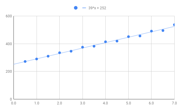
Okay, you’ve made me have to do a quick experiment. Being spring-loaded and within the elastic limit of the spring, the force should be linear (Hooke’s Law). So, all I have to do is collect some measurements of the force vs. displacement. I grabbed my digital kitchen scale (who doesn’t measure bulk ingredients by mass?) and headed over to the machine.
Experiment: Force vs. Displacement
mm  | "grams"
0.5 | 272
1.0 | 290
1.5 | 310
2.0 | 335
2.5 | 346
3.0 | 375
3.5 | 382
4.0 | 414
4.5 | 419
5.0 | 451
5.5 | 456
6.0 | 491
6.5 | 495
7.0 | 537
The measurements in millimeters are the displacement of the Z axis, with zero defined as the diamond point in contact with the surface but not exerting any measurable force. (Note: My scale reads in “grams”, but obviously, it means the force equal to the weight of the displayed mass at 1G. Most likely nobody cares, but while I simply can’t use grams as a unit of force, it’s more relatable than actually using Newtons, hence the “grams”.) Charting this out and doing a linear regression, we get the following:

According to the linear regression, the force would be zero at Z = -6.5mm, which is basically a measure of the amount of preload compression on the spring.
Analysis: Confirmation By Measured Dimensions
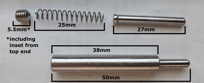
So, how does that compare to actual dimensions? Well, conveniently, I happen to have purchased extra parts. Here’s an annotated breakout of my diamond drag bit.
- Overall length: 50mm
- Body length: 38mm
- Tip length: 27mm
- Spring length, uncompressed: 25mm
- Set screw length: 5.5mm (including the length of the set screw and the amount it’s inset in the top of the tool)
We can then calculate the spring preload by taking the overall length (tip, spring, and set screw) and subtracting the two ends to get 7.5mm (50mm - 27mm - 5.5mm). The difference between the two values (6.5mm vs. 7.5mm) is likely made up of a combination of experimental error, measurement error, and possibly differences in the actual pieces being measured (since I didn’t disassemble the actual tool I used for the force measurements).
I’m sure if I took more care with the experimental setup and measurements (and took more data all around), the experimental error could be reduced. Regardless, it was more of a sanity check for the useful result, which was determining the approximate preload in the spring and the resulting force-vs-displacement curve. So, what is my answer to your question?
Conclusion
Given the preload on the spring, if you plan your Z-zero to yield about 3mm of tip retraction, a variation in stock of +/-1mm will only result in about a 10% difference in force applied. Therefore, I would be fairly confident that small displacements in the surface of the stock are unlikely to cause noticeable differences in the engraving.
(Note: Obviously, as you pass full extension, the force goes immediately from the preload force to zero, which would be distinctly suboptimal.)
Application to Carbide Create
If you made a “Texture” toolpath with “Max Depth” basically set to a very small value, then only your retract height would be relevant to the Z axis. As long as your retract height was high enough to clear full extension, the slightly wavy actual Z travel wouldn’t be relevant. However, the actual endings of the texture toolpath’s subpaths are not right on the edge of the shape. They don’t quite reach. I’ll have to see whether that turns the segment-exit edges “fuzzy” in practice.
