I’ve been trying to learn about work offsets, and wondering if i can use them with the Shapeoko3 using the MDI
Can they be used? what is the process for using them?
I’ve been trying to learn about work offsets, and wondering if i can use them with the Shapeoko3 using the MDI
Can they be used? what is the process for using them?
Yes, work offsets are supported by the firmware, Grbl, used in the machine.
The problem is Carbide Motion masks them from the user, and uses one (G54?) (or more?) internally and disallows normal access. You can access them by using a slash to directly interact with them in the MDI, but there is the possibility of a conflict w/ at least the first.
If you use a 3rd party tool to access them, best practice seems to be to re-send the machine defaults if one switches back to CM.
See: https://wiki.shapeoko.com/index.php/G-Code#Using_the_Work_Coordinate_Systems and https://wiki.shapeoko.com/index.php/Communication_/_Control
If you are serious about using different work offsets, I would look into CNCjs. Just be carefull. If it is not set up properly, by not having the correct soft limits or having soft limits turned on, there is nothing keeping it from telling the machine to travel further than it is capable of other than metal.
If you need multiple work offsets, it is really good. IMO
Work offsets, at the most basic level, are just the locations of your work zero defined as a distance from machine zero (home).
Everyone that has homing switches uses work offsets.
Can you be more specific with what you’re trying to do?
to be more specific about what im trying to accomplish…
im attemping to find a way to be able to use multiple tool lengths without having to re-zero each time i put in a new tool
i use Fusion 360 to set up my toolpaths, i know that their tool library unfortunately, does not affect the gcode z-height… meaning if i put in a long tool, it crashes, or a shorter tool, it mills in the air doing nothing.
the bits i use, have a collar added to them, for a predicable length every time they are inserted into the router.
im thinking by using a work offset, for each different tool length… i can make it so i only have to zero once.
im making a batch of wooden products, and trying to get some consistency between them, i figure setting a work offset for the first position, and ones for each tool following, would help with that as well.
i’ve attemped to use that before, as well as a few others, but could not get them communicating with the shapeoko for some reason, i might have to look into them again when i get a chance.
could you provide an example, or the steps required, to set, and activate a couple different offsets?
what is the conflict that you speak of?
Commands are at: https://wiki.shapeoko.com/index.php/G-Code — the conflict is that G54 at least is used by CM to track things and overwriting the values will cause unpredictable problems.
@mrdezzz Are you running one job with tool changes or separate jobs with different tools? Stock always the same thickness? Zero on top or bottom? What you want to do is possible. If you can be more specific, I can tell you what I’d do.
I think you can get what you want by changing the setup for each tool in Fusion. If the difference in tool heights are consistent and known, you can “trick” Fusion into cutting less or more for each tool in the Setup.
I’d hate to lose my simulation in Fusion doing it that way.
Grbl supports dynamic tool length offsets (G43.1) and clearing of tool length offsets (G49), but G43.1 is not persistent, so it will clear on a reset.
You could use different coordinate systems (G55, G56, etc), but that would only make sense if your Z zeros were fixed (cutting stock of the exact same thickness or cutting all the way through stock of the same thickness).
You could always just use G10L20P1Z___ to adjust the work Z when you switch tools.
Those little collars can move and/or wear, so I wouldn’t rely on them for work needing high levels of precision.
The G10 line is exactly how I would do it.
I did not know that command. I really need to study GRBL. Industrial CNC’s have tool offsets stored in H0* that are called up with a tool change.
I realized that Fusion idea was kinda hacky, but your G10 solution seems like the proper way to go about this, and there is no need for different work coordinates either.
Im running one job with multiple tool changes, each tool has its own file generated from fusion 360.
stock is generally the same dimensions, within a millimeter or two.
I zero on the top of the stock
my current process is…
insert stock
insert tool #1 (my longest bit for drilling deeper holes)
run File-A (made for tool #1)
clamp another stock piece on top of the first stock (so they are machined together)
run File-B (still using tool #1)
insert tool #2 (a short 1/8" bit)
run File-C (with my current setup mentioned above, no need to zero this bit)
remove finished parts
in the future, ill probably be adding a few more steps and tool changes in this process, but this is what it is for now.
tricking Fusion is essentially what im doing now… but it screws up the simulation… turns out IRL just fine though lol
does the different coordinates not also include setting a position for z?
could i use a different coordinate position, and only change the z-height, to makeup the difference from one tool length to the next tool length?
that sounds interesting, perhaps this would work with the pass-through in fusion?
that way when i run the file, it automatically adjusts the work Z, so i don’t have to manually type it into the MDI
How would i use this command?
if i type in G10 L20 P1 Z10
will that just make everything following the command be 10mm higher than before?
good to know thank you, but im not too worried for the time being, im just working with wood, and small pieces, so if one gets scrapped, not a major loss.
I’d call that multiple jobs, but I get it. So you’re not actually generating M6 tool change commands within one file.
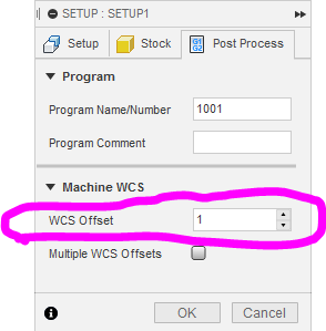
Based on your requirements, I’d use different WCS for each file with the only difference being the Z. If you use a different setup in Fusion for each tool, you can set the WCS in Fusion (1=G54, 2=G55, 3=G56, etc).
Just make sure you set the zeros for those WCS before you run the files.
what is the general workflow of using G54-G59 positions?
if i wanted to set these, would i…
go to MDI tab, type in G55
then zero my X, Y or Z
Jog to another location, type G56 in MDI tab
zero XYZ
at this point here, if i use the quick jog to XY position… it would jog to the Zero position i had set for G56?
and if i wanted to quick jog to XY position set in G55
i would first type G55 in the MDI tab, then click the quick jog to XY position under the jog menu?
is this generally how it works? or am i wayy off here? lol
That’s pretty much how you do it, but the specific commands are a bit different, see: http://citeseerx.ist.psu.edu/viewdoc/summary?doi=10.1.1.15.7813 and https://wiki.shapeoko.com/index.php/G-Code
Just don’t use G54 if you’re using CM, and if you use something else, and then switch back to CM, re-send the defaults so that CM will have a known state.
This topic was automatically closed 30 days after the last reply. New replies are no longer allowed.