Can someone help with first 3D project

Hello - after watching some, but not all, of the recommended video/posts I jumped in to trying to do a 3D project and have made some progress, but I’m at a point now where I don’t understand how the changes I’m making affect what the cut will be.

I’ll explain what I’m trying to do and attach the file and will appreciate any advice anyone cares to offer.

I downloaded one of the D&D dice box projects from CutRocket to make for my son and want to cut a 3D image on the top, so it will be a flip project. What I’ve attached is the flip side with just the top of the box lid.

Stock is 15/16" in thickness leopardwood and the inside pocket for the lid will be 0.45", so there’s just under 1/2" (0.4875") of hardwood to work with, although I wouldn’t expect to cutaway even half of that.

The 3D preview shows a deep pocket with the image in relief at the bottom, which is exactly what I expected, because once I cut out the top the pocket won’t be there. What I can’t figure out is… Well, a few things:

  1. Why is the pocket I’ve defined so deep (what did I do to make it that way)? Seems like it’s cutting away a lot more material than is necessary - the highest part of the image can start at the top of the stock can’t it?
  2. Do I need the Base component (Add Shape) in addition to the imported image element, or just the image?
  3. How do (or don’t) Merge Type and Base Amount work with each other and affect the cut of either the pocket around the intended 3D image?

Sorry for the string of questions, but I think I’m pretty close and just need some experienced guidance to get me over the line.

Thank you in advance!

Project file:
D&D dice box TOP (downloaded).c2d (168.1 KB)

Image file:

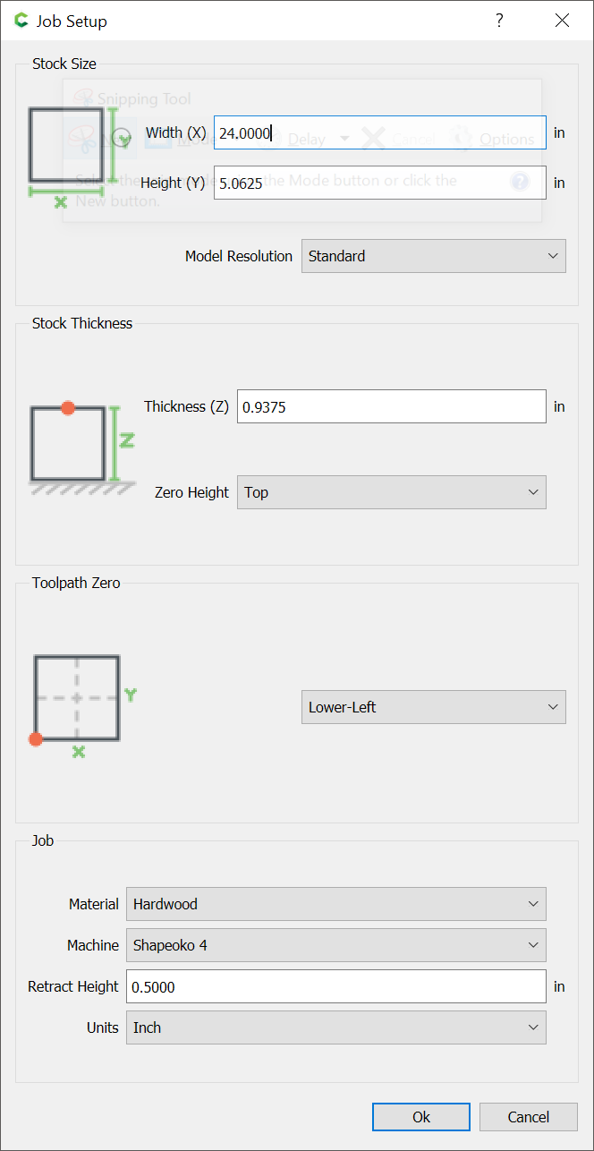
  1. You have defined the stock thickness to be almost 1" thick:

  1. See above — If your stock is actually 1" thick, then yes, add a Base to get the thickness to match

  2. Base amount adds that thickness at the bottom — the various merge types interact w/ the preceding components, see:

Stock is actually 15/16" in thickness (sold that way (Rockler) and measured to be accurate). So the “Base Height” in the Model Shape for the image component should be the same as the stock height? Pointless question probably, but why doesn’t the Base Height default to the value for the Stock Height?

I’ll read the Modeling Instructions by @Gary to get a better understanding of what I should be doing.

Thanks!

Anything which doesn’t come up to the stock thickness in the 3D model will be cut away.

If you want the 3D model to be only 0.25" thick, and to cut away almost 3/4" of material, then model it thus. I suspect you want the design to be more like:

The simulation you posted shows pretty much what I was looking for.

I’m sorry if I’m not explaining or even understanding the terminology correctly. CNC and 3D CNC are both still new for me - I’m working on it. I get that it can be explained to me, but not understood for me …in progress.

The “3D model” is the 3D element of the project, not the complete stock thickness?

I’m confused by, “cut away almost 3/4" of material” because, 1. that’s way more than I want to cut away (ideally I’d cut away 1/4”) 2. It doesn’t look like the simulation, which looks like the depth I want to cut, so I don’t cut into the pocket from the other side.

Again, sorry for what might be overly simplistic questions.

Your model (the 3D components) are scarcely 1/4" thick — you need to increase their thickness — I did this by increasing the thickness of the first component.

1 Like

Thank you. I appreciate your help. Sorry it took a few times to get it through to me.

This topic was automatically closed after 30 days. New replies are no longer allowed.