Modeling Instructions

I’ve been playing with the pro version of CC since the free version became available (thank you!) - and have been experimenting with modeling. I’ve watched all of the videos that are available on YouTube and have read through many posts here in the forum. I’m not bad at it - but to be completely honest, I don’t feel mastery of the dialogs for modeling. I discover what I want through hit and miss attempts with the parameters, etc.

I know what I want to see and then try all different combinations of parameter settings until I get what I want.

The process is made more difficult by the fact that many of the parameters are unavailable for editing, once you press ‘done’, so you lose the chance to try different combinations of component parameter sets to achieve a desired result…once you move on to another component. That is, you can no longer modify all of the parameters of the first component, once you start working on a second (I’d like to see that changed, but that’s the subject of another post that’s more appropriate after I gain some mastery).

Does an instruction guide exist that takes you through each of the parameters and states exactly what they mean? In particular, the parameters for Height Limit and how they interact with the Merge Type. For example, if I use SUBTRACT merge type with a height limit of “Scale Height” for a Height of .5" - is that lowering the component by .5" or is it lowering it to a height of .5" (i.e., if I were cutting it from a block that was .75", is there .25" left or .5" left after I subtract the shape?). What about if I use “Limit Height”? That’s just one example, how do the height limit parameters work with the other merge types: MIn, Max, Multiply Equal…

I think I understand until I do something and it doesn’t work…then I realize that I don’t really understand. Does a document exist that just describes all of the parameters and how they interact? I’d like to get to a point where I can previsualize what I’m going to see when I’m dialing in the parameters.

Thanks.

2 Likes

There are a couple of tutorials:

Post the file you are stuck on and we’ll do our best to help.

@WillAdams Will, I’m not stuck on any particular file. It’s not a question of solving a particular problem. I want to know what the parameters do, so that I can feel that control of using them like tools…to get whatever I’m visualizing to happen.

I’ve looked at several of those posts before - though not all (and I will go and read through those now - thanks for posting those)…but learning from threads of comments around a specific problem is a better technique once you have the basics under your belt. A simple description of what each parameter does, relative to the other parameters, would be the basis for all the rest of the discussions. At least for the way I learn.

OK…I’ll say no more until I’ve read through the posts you refer…hopefully, one of them will be what I’m looking for.

  • G
1 Like

@WillAdams OK…so I’ve read through all of these and no…they don’t answer the basic questions. What do each of the parameters do, how are they used, and how do the height limiters impact each of them? The dish is one that I’ve watched MANY times…and it definitely explains how to make a dish. But it doesn’t really go into the permutations beyond the need for the dish - and therefore falls a bit short for what I’m after.

Anything else available?

2 Likes

I’m afraid we don’t have a repetitive set of examples showing how each setting interacts.

We’ll have to see if we can work one up.

Until then, if you’re stuck achieving a particular effect, please make a post describing it and we’ll do our best to work through it with you.

OK…I can’t just let this drop. I started to experiment with the modeling and attempted to observe the behavior of the various parameters. I’ve begun to chart out those observations. This is, by no means, complete (and may even be inaccurate) and I would much rather have C3d developers post what’s really going on in the calculations, but here are my findings - so far. I cannot figure out what the real purpose of max and min are…and multiply SEEMS to have no purpose. I need to do more observations.

This is the design I worked with:


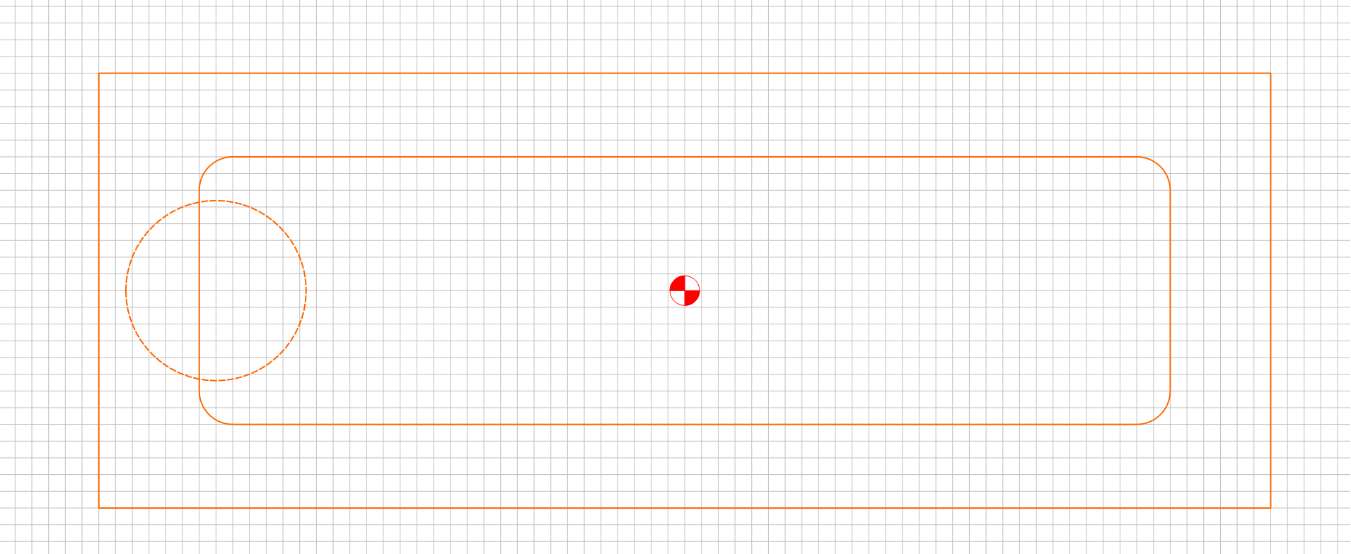
Component 1 is a flat base of 5" (Add 5" Flat) for the large square. I then started to apply different parameters to the fillet’d design component to make observations. Then, I started to apply different parameters to the circle to try to see how the parameters blended between components.

Here’s my current chart:

Meaning of “Height” Parameter
Shape Height Limit Add Subtract Min Max Multiply Equal
Flat None Amount Added Amount Subtracted Baseline of piece Top of Piece Undetermined Resultant Height
Limit N/A N/A N/A N/A N/A N/A
Scale N/A N/A N/A N/A N/A N/A
Round None No Bearing (Determined by Angle) Relative to previous height No Bearing (Determined by Angle) Relative to previous height Baseline of Piece (no Round) Top of Piece (No Round) Top of Piece (No Round) No Bearing Round starts at bottom of piece
Limit Truncates round (Determined by Angle) at an additional height; relative to previous height Truncates round (Determined by Angle) at an subtracted height; Relative to previous height Baseline of Piece (no Round) Height at Previous Height (No Round) Top of Piece (No Round) Truncates round (Determined by Angle) at an additional height; Starting at bottom of piece
Scale Height of Peak relative to previous heights Depth of the Peak. Relative to previous height Peak starting at baseline Truncated to previous lowest height Peak height starting at previous height Top of Piece (No Round) Resultant Height of Peak, Round starts at bottom
Angle None No Bearing (Determined by Angle) Relative to previous height No Bearing (Determined by Angle) Relative to previous height Baseline of Piece (no Round) Top of Piece (No Round) Top of Piece (No Round) No Bearing Angle starts at bottom of piece
Limit Truncates angle (Determined by Angle) at an additional height; relative to previous height Truncates round (Determined by Angle) at an subtracted height; Relative to previous height Baseline of Piece (no Round) Height at Previous Height (No Round) Top of Piece (No Round) Truncates round (Determined by Angle) at an additional height; Starting at bottom of piece
Scale Height of Peak relative to previous heights Depth of the Peak. Relative to previous height Peak starting at baseline Truncated to previous lowest height Peak height starting at previous height Top of Piece (No Round) Resultant Height of Peak, Angle starts at bottom

I will try to keep this updated as I learn more…but I would LOVE for folks to chime in on their observations (or knowledge) with regard to these points.

2 Likes

That’s the behavior I saw with LIMIT HEIGHT. But let me try it.

@WillAdams Nope…doesn’t work for me.

Drew a circle and extruded it. Height seems to be meaningless, as the actual height of the object seems more determined by the angle than the height parameter. The height parameter seems to have no bearing on the actual height when “FLAT” is chosen as a Height Limit.

Then choosing max and setting the height parameter had no effect and I went to the bottom of the height parameter limits (.001)

I just tried changing the Base Height parm, thinking maybe that had more of a bearing on the component than the shape parameter “Height”…but it does not. Base Height seems to just add to the bottom of the entire component…lifting it a particular height.

@robgrz Hey Rob, I know YOU understand the purpose of each of the parameters in the Modeling dialog…could you have one of your devs document the purpose of each parameter in a way that can allow us to predict what will happen when they’re used? This rather than us having to say “Seems to behave like this”…?

1 Like

Max seems to set a base level for the extrusion, regardless of other elements:

Min uses that base level, but leaves all other elements in place and does not cover them:

@WillAdams Can you please post your design? Just a snapshot of it, no need for the c2d. Also…this looks like you have more than one component modeled. What combination of modeling components are we looking at?

Sure! Not much to it:

ccminmaxex.c2d (1.7 MB)

The big thing is that some of the options only interact with the existing model.

Once I’ve caught up on things I’ll have to do a chapter like to:

https://willadams.gitbook.io/design-into-3d/2d-drawing

for the 3D modeling stuff (or maybe do a separate volume for decorative work).

Oookay…so Min takes the lower value of any overlapping components…and max takes the largest. Makes sense.

The use of a base height is unnecessary for this.

I guess I get it: The Height Parameter has no bearing on the Merge Type and vice-versa. This makes sense. The merge type is analogous to layer blend modes in Photoshop…although there actually is some interaction, in that the component is inverted when Subtract is selected.

So now…what does Multiply do? I did not get the result I expected when I changed your second component to Multiply!

1 Like

This topic was automatically closed after 30 days. New replies are no longer allowed.