Thanks, Kool, for the suggestion. Following up on your ideas I discovered that FlatCAM will let you make a separate Gcode file for each drill size, so that turned out to be an easy fix.
I’m still wrestling with how the 2 sided pcb tool handles mirroring. Something I’m doing is resulting in the mirrored alignment holes ending up outside the bounds of the board stock. Here are some screen shots of the steps I’m taking that get this result. I’ve played around with the sequence and tried some variations but I haven’t been able to figure out how to get the alignment holes in a good place.
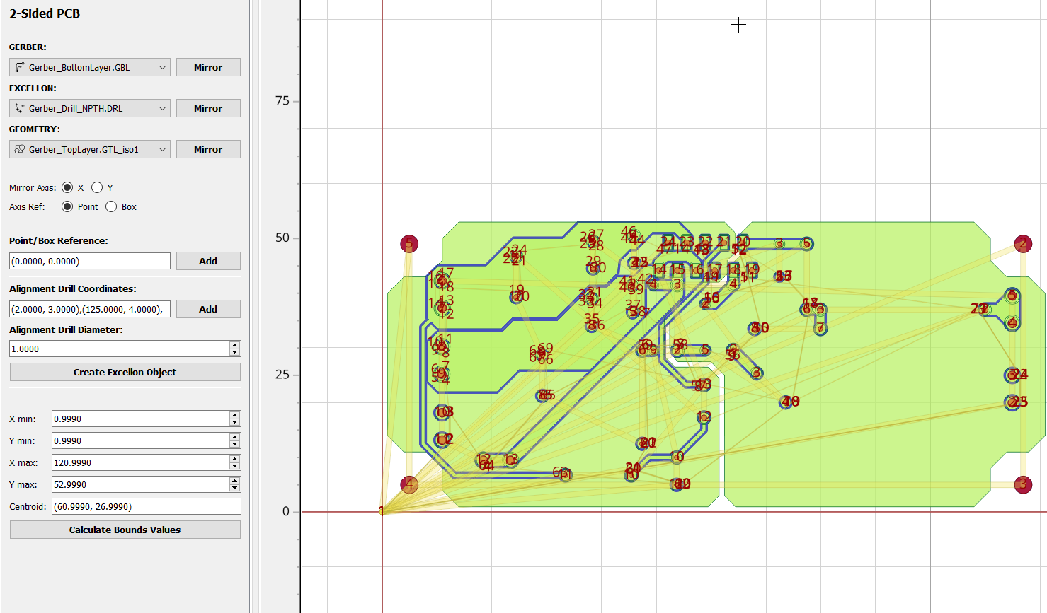
Before mirroring and creating alignment hole geometry. I’ve set the coordinates for the alignment holes.
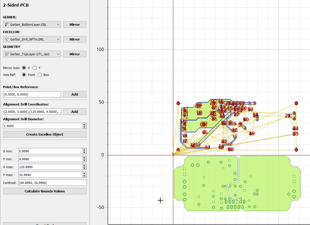
After pressing the mirror button.
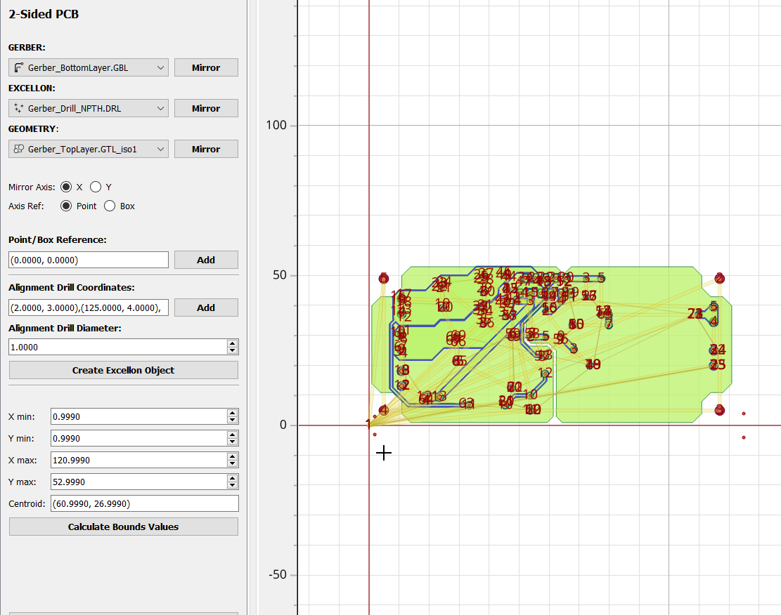
After pressing the “create excellon object” button.

After pressing the “mirror” button a 2nd time.
It seems that the only way this could work is if you zero the cnc nearer to the center of the copper clad. Is that normal?