I’m having trouble with a gerber file conversion. The original layout includes 2 large copper zones and I’m using FlatCAM to convert the gerber file to a format that the carbide motion will work with. But carbide copper seems to not recognize the existence of the copper zones. It also doesn’t seem to track the cutouts (sorry, I can’t remember the technical name) around the!) ground plane solder points (to make the soldering easier…less heat required). From what I read on this forum I’m expecting the answer to be that carbide copper is not capable of doing this. Is there another software that will create the G code from a gerber so I don’t lose the copper zones, etc?

1 Like
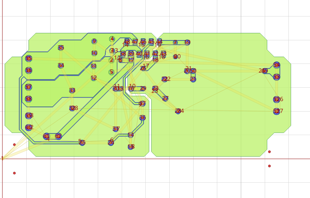
Here’s the original top layer:PCB_LM3886 Amp Easy EDA.pdf (121.4 KB)
Why not generate the gcode in FlatCAM?
I’ve achieved excellent results using FlatCAM to generate and AutoLeveller to post-process PCBs routed in KiCAD: Nomad Level Calibration
I haven’t explored Carbide Copper thoroughly because the FlatCAM workflow works so well for me. I suspect that at least part of your issue is that your EDA tool isn’t generating thermals (those are the links between a pad and a copper pour) in a way that Carbide Copper understands, either because the shape in the gerber is unsupported or is too small to mill effectively.
1 Like
Will auto-leveler sample the board on a grid pattern to get a virtual picture of the flatness and the compensate when routing? I’ve read that Bcnc will do that but there doesn’t seem to be anything in carbide motion. We’ve had some challenges with flatness issues so hoping to get this going as well.
I didn’t know it would do that. I’m pretty new to cnc and this is my first project. The person that is helping me is also pretty new so together we’re figuring out how to work with it . I don’t own the nomad but have access to it every week for a couple of days. I’ll be able to try again next Wednesday.
From what I’ve heard the Nomad is really particular about file format. Just wondering if you’ve seen Gcode from FlatCAM working on the Nomad?
No, Autoleveler won’t automatically sample the board for flatness, at least with the Nomad. Autoleveler isn’t designed to work with CNC machines that use grbl as their machine controllers. Additionally, the Nomad has no feedback system* to detect when its probe (or tool) has made contact with the board.
The link in my last post has a workaround that I devised to get board thickness data into Autoleveler using semi-manual probing and a dial test indicator. It also has a couple of tips on how to get better results even if you don’t have an indicator to measure the board thickness with.
(* This isn’t strictly true if you have a Carbide 3D touch probe, but the probe isn’t sold with the Nomad and is mostly used by Shapeoko owners to quickly determine work-zero and tool length. I haven’t heard of any Nomad owners using it to probe PCB stock)
2 Likes
I used flatcam to generate gcode but I suspect I’m missing something. As a test, I started with trying to drill alignment holes for my pcb. In flatcam, I was able to generate an Alignment Drills excellon file and create a CNC job callled "Alignment Drills_cnc. Carbide Motion accepted the file without complaint but when I went to run it , the drill bit move slightly left and then nothing. I didn’t get any error messages from Carbide Motion so it seemed that the program thought it was done. Being so new at this I’m tempted to assume I need to do more homework on how to work with it but thought I would post one more time just in case this should have worked.
Thanks for the link. Likely I will need to dive into leveling more at some point. Right now my biggest issue is getting the nomad to work at all.
It occurred to me that this design might be too tight for cnc. It’s intended for a pcb manufacturer so perhaps a cnc won’t be able to create the close tolerances in the design and that is why carbide copper is omitting them?
Got any flatcam files you can share?
The tightest rules I have used with the Nomad were something like 10/10, which is skinny enough to sneak between two through-hole pads belonging to something like a pin header. I think 8/8 is probably also doable but haven’t had a need to go there.
I personally prefer to use the most relaxed rules I can get away with for a given design. Even if you’re not prototyping it on the Nomad, the design will have a better chance of coming back from the board house without defects if you use rules that don’t test their equipment.
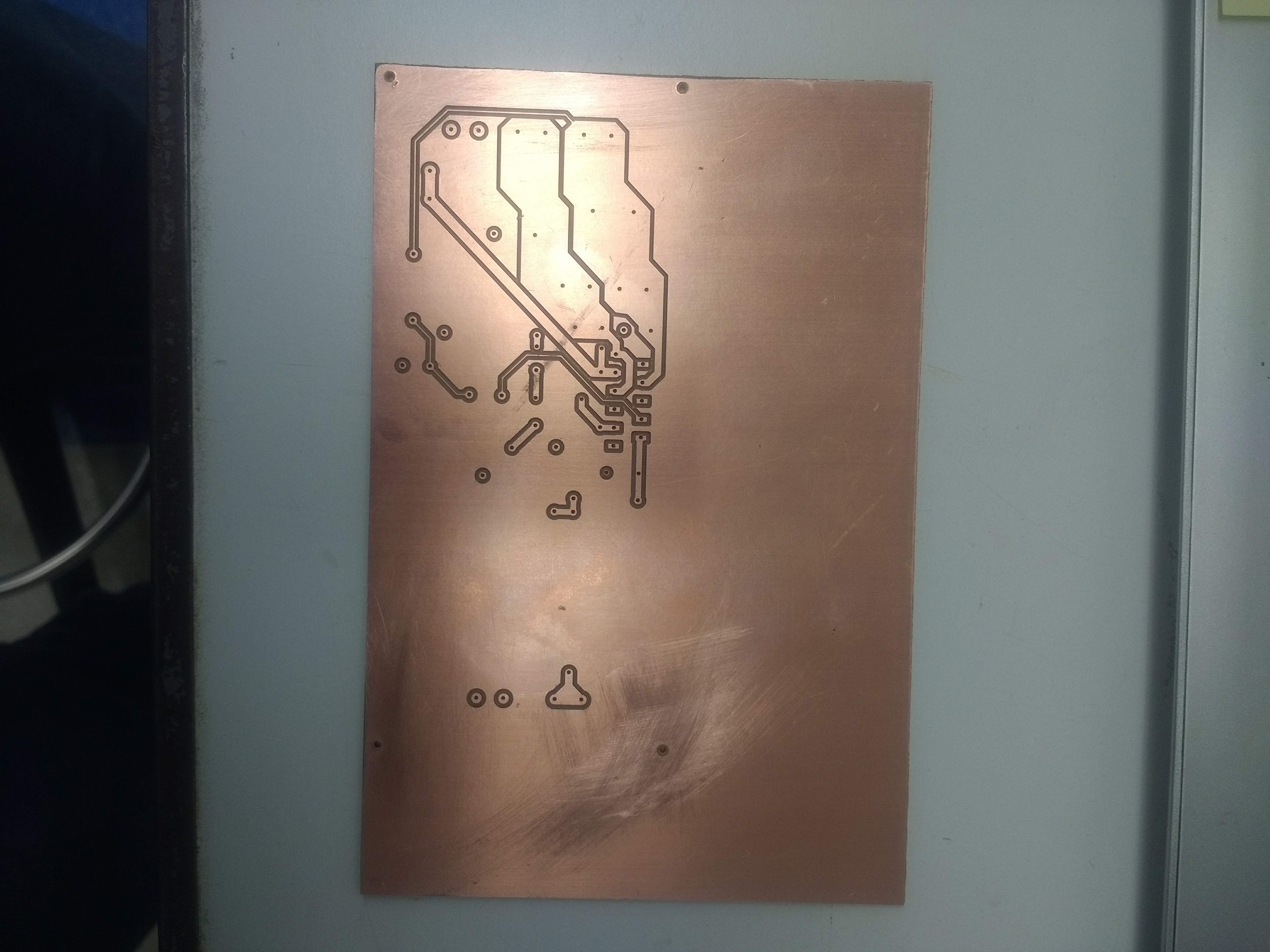
I took another stab at it today and was able to get it partially working. I found a tutorial on youtube that has helped a bit. I’m able to get carbide motion to accept the gcode and it seems to work okay. I didn’t have enough time to do a whole board however. Now I’m on to working with finding ideal settings for my machine.
I was able to get flatcam files to work today so I won’t be bothering with carbide copper at this point. Sorry to be so uninformed…what is 10/10 refer to?
10/10 means 10 mil trace width, 10 mil clearance between traces. You’ll see that shorthand most places that deal with PCB fab, since it’s also something of a marketing point when the PCB house can reproduce tight design rules.
1 Like
That makes sense…thanks for explaining.
Can anyone recommend a good tutorial for creating 2 sided pcb’s in flatcam? I’ve found a few different things on youtube but nothing very thorough. Case in point… attached is a .pdf of what I got when i tried to create alignment holes. The tutorial i was following said I only needed to put 2 holes in and then the mirroring function would automatically set the other two holes to make 4 in total. But mine ended up mirroring differently than I expected and I’m not sure why.
got the nomad going pretty well. Have successfully drilled alignment holes and milled the top layer. I next ran the “drill holes” .cnc file and it drilled all of the holes the same size as the first bit I put in. I used flat cam and although FlatCAM tracked the different drill hole sizes, Carbide Motion didn’t. Is there a way to create separate gcode files?
iirc flatcam doesn’t really keep track of how big each hole is – it just generates gcode from your Excellon drill hit file. The drill sizes are recorded in the Excellon file, but flatcam won’t add tool changes to the gcode it spits out. It expects you to keep track, using the right size drill for the holes you need and changing bits as required.
I think there are two workarounds here (I don’t have flatcam open in front of me, so these ideas might take some massaging to get working properly)
- First, you could generate a separate Excellon drill hit file in your PCB design software for each size hole you need, and import each one into flatcam.
- Alternatively, you can just import your one original Excellon file into flatcam multiple times, and delete all the holes that aren’t of a certain size from each of the intermediate geometry layers it generates. That will let you generate separate gcode files for each drill size, and you can change tools between running each one.