Moot, now that you’ve recreated it - but once I knew where to look, I also recreated it., Win11.
1 Like
We got it fixed, so it should be in the next build. We’re waiting to finish one more new feature before we push it out. (The new feature is, to quote Larry David, pretty… pretty… pretty good)
4 Likes
The bug is the Cutter Check command is fixed, and we got the new feature in a beta for the weekend: Nesting in Carbide Create Pro
2 Likes
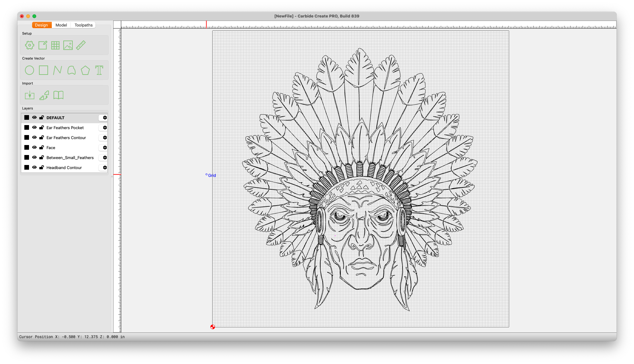
Hello and thank you for the beta. I’ve attached two images. One is an image showing dxf files imported in V7 and the other in V8. V8 is distorting the vectors in weird ways. I’m not sure how or why but wanted to give you the info that I saw. Adobe Illustrator CS4 exported as DXF files w/options (AutoCad Version 2004/05/06 • 1:1 Scale • True Color • Raster Format PNG • Preserve Appearance)

We’d need a copy of the DXF to debug it
1 Like
Here you are sir. 1111111111111111111111111
Are we talking about ear feathers pocket?
The biggest change was to the “Warrior_CFL_LargeFeather_Tips” however most files were affected.
I think we found it. We’ll have a fix in the next release.
2 Likes
Thank you! In the attached image it looks like it’s “bending” the corners or softening the corners, if that makes sense.
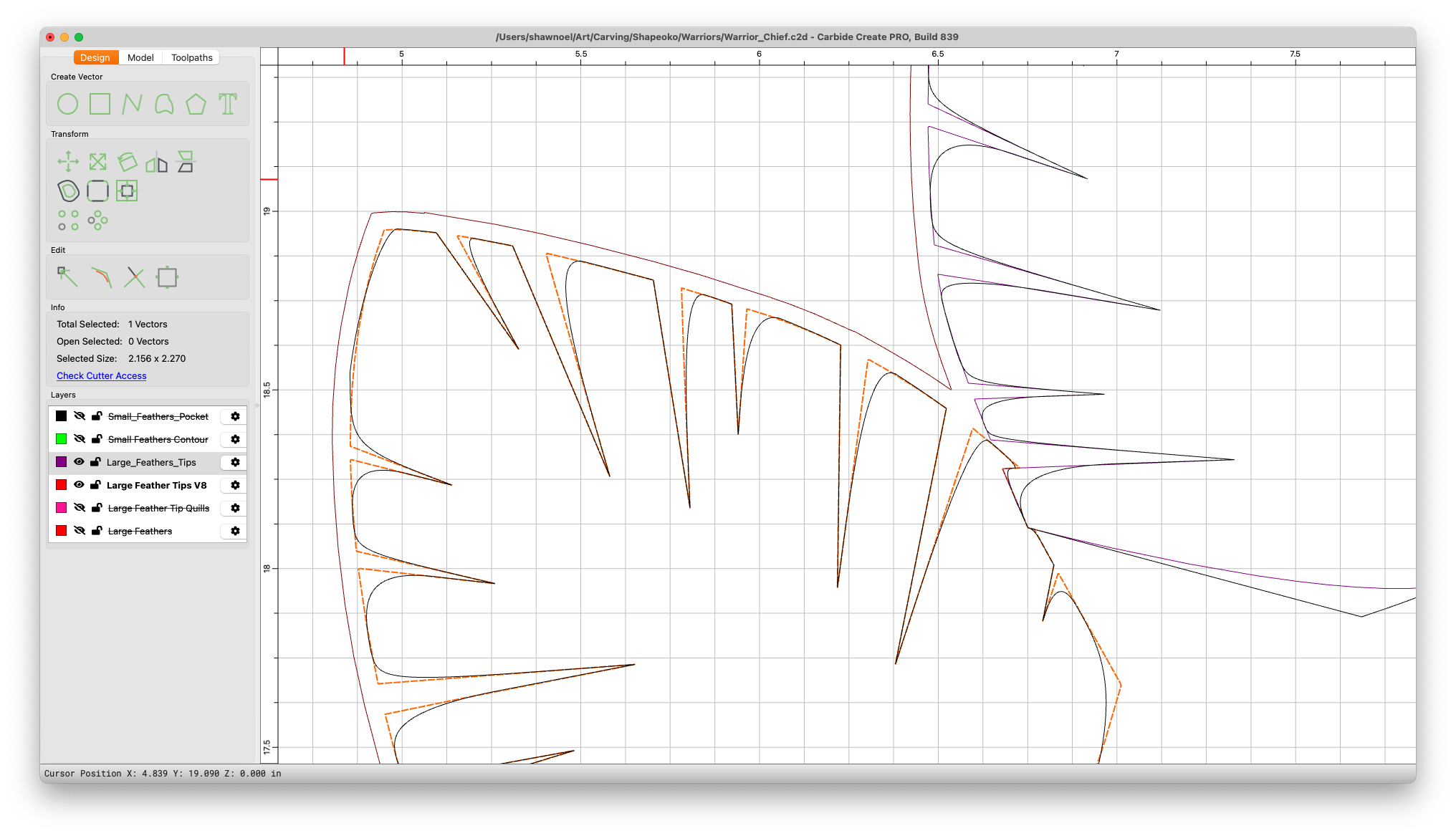
Yep, we were inserting extra knots when importing the splines.
2 Likes
I’m assuming “Nodes” and thanks again for the future fix.
Actually, knots. That was an autocorrect.
1 Like
Any chance on adding a larger layers window and the ability to move layers the same way tool paths are moved? Clicking move up and move down 7-8 times is a bit tedious. ![]() Thanks again for the new beta!
Thanks again for the new beta!
Also, in the next release
3 Likes
Yes!!! You guys rock!!!
1 Like
Thanks for the great work. Anything on the horizon which might include a dedicated tool for creating arches? Currently still having to greatly enlarge the document size, create circles, then chop off unwanted segments. Just curious; thanks.
Why not just draw a rectangle of the desired size, then round off the corners?
Or, make everything aligned to the grid, then use Node Editing?
If you’ll provide an example/set of dimensions will gladly walk through this with you.
Hey William.
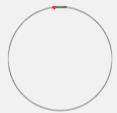
Here’s the shape I needed, drawn easily in fusion 360:
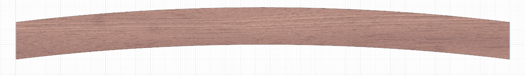
Width is 33 inches. The two arches are parallel, 2.5 inches apart, and each with a radius of 136.625 inches.
The apex (center point) of each arch is 1” above its respective end points.
I did not know you could use rounding corners to achieve this shape.
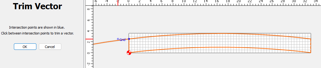
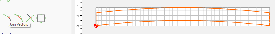
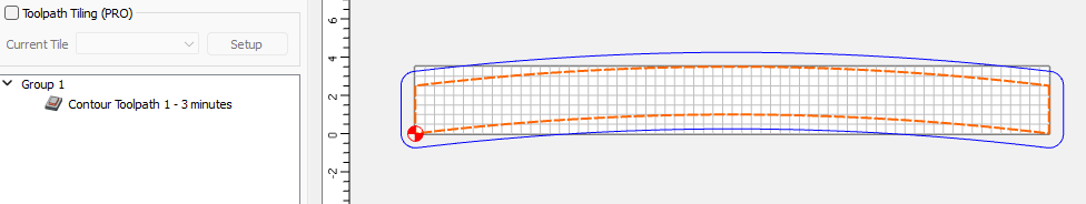
I temporarily enlarged the canvas size and drew two circles of the required radius, then chopped off desired segments. This worked, but cutting on the machine was very slow because there were four tool paths instead of just one. Each path was cut one at a time and not in order according to position. Very inefficient. By the way, that reminds me of another question, is there any way to re-order the segments when drawn or to combine them into one tool path?
How would you have done this?
Thanks again.